Tài liệu Bridging and Switching pptx
Bạn đang xem bản rút gọn của tài liệu. Xem và tải ngay bản đầy đủ của tài liệu tại đây (1.15 MB, 56 trang )
7
Bridging and
Switching
CERTIFICATION OBJECTIVES
7.01 Bridges and Switches
7.02 Functions of Bridging and Switching
7.03 The Spanning Tree Protocol
7.04 1900 and 2950 Configuration
✓
Two-Minute Drill
Q&A
Self Test
CertPrs8 / CCNA Cisco Certified Network Associate Study Guide / Deal / 222934-9 / Chapter 7
Blind Folio 7:1
D:\omh\CertPrs8\934-9\ch07.vp
Monday, August 04, 2003 11:53:05 AM
Color profile: Generic CMYK printer profile
Composite Default screen
B
ridges and switches are both layer-2 devices, functioning at the data link layer of the OSI
Reference Model. Even though they are both layer-2 devices and have many similarities
between them, they also have many differences. With advancements in hardware and
technology, switches perform faster and have many more features. However, the basic functions
of these two devices are the same. This chapter covers the functions of bridges and switches, the
Spanning Tree Protocol (STP), and basic switch configuration tasks on Cisco’s Catalyst 1900
and 2950.
CERTIFICATION OBJECTIVE 7.01
Bridges and Switches
The main function of bridges and switches is to solve bandwidth, or collision, problems.
Remember that in Ethernet, multiple devices can share the same segment, so there is
a chance that more than one device might try to transmit at the same time, creating a
collision and a retransmission. The more devices you have in a shared medium the more
likely collisions will occur. This doesn’t mean that Ethernet is a bad data link layer
topology; it’s just the way it functions.
In the old days of networking you used hubs to connect devices together, or
used 10Base5 or 10Base2 cabling (where you would have many devices on one wire).
If you experienced constant or excessive amounts of collisions, you could use bridges
(and later on, switches) to break up the user devices to multiple segments, where each
segment would have fewer users, and thus fewer collisions. You could also use a router
to perform this function; however, the disadvantage of a router is that it costs a lot more
than a bridge or switch. This section provides a brief overview of bridges and switches.
Bridging Versus Switching
Even though bridges and switches both operate at layer 2, there are many differences
between them, as Table 7-1 shows.
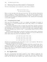
Perhaps the biggest difference between the bridges and switches is performance.
Bridges switch in software, providing a frame rate of about 50,000 frames per second
(fps). Switches, on the other hand, perform their switching in hardware, using ASICs
(application-specific integrated circuits). ASICs are specialized processors, and in the
switching world, they are built to do one thing: switch frames very fast. As an example,
2
Chapter 7: Bridging and Switching
CertPrs8 / CCNA Cisco Certified Network Associate Study Guide / Deal / 222934-9 / Chapter 7
D:\omh\CertPrs8\934-9\ch07.vp
Monday, August 04, 2003 11:53:05 AM
Color profile: Generic CMYK printer profile
Composite Default screen
the 1900 switch has a frame rate of 500,000 fps and can handle all ports at their
maximum speed. Please note that the 1900 is a low-end switch. On Cisco’s higher-end
switches, the frame rate is in the millions of frames per second.
Methods of Switching
Another difference between bridges and switches is how they switch frames. The
switching method affects how a layer-2 device receives, processes, and forwards a
frame. Bridges support only one switching method, store-and-forward, while switches
might support one, two, or three different switching methods. The three switching
methods supported by layer-2 devices include the following:
■
Store-and-forward
■
Cut-through
■
Fragment-free
The following sections cover these three switching methods.
Store-and-Forward
Store-and-forward switching is the most basic form of switching. With store-and-forward
switching, the layer-2 device must pull in the entire frame into the buffer of the port
and check the CRC (checksum) of the frame before the layer-2 device will perform
any additional processing of the frame. When checking the CRC, the layer-2 device
will calculate a CRC value just as the source device did, and compare this value to
Bridges and Switches
3
CertPrs8 / CCNA Cisco Certified Network Associate Study Guide / Deal / 222934-9 / Chapter 7
Functions Bridges Switches
Form of switching Software Hardware (in ASICs)
Method of switching Store and forward Store and forward,
cut-through, fragment-free
Ports 2–16 Possibly hundreds
Duplexing Half Half and full
Collision/bandwidth domains 1 per port 1 per port
Broadcast domains 1 1 per VLAN
STP instances 1 1 per VLAN
TABLE 7-1
Bridge and Switch
Comparison
D:\omh\CertPrs8\934-9\ch07.vp
Monday, August 04, 2003 11:53:05 AM
Color profile: Generic CMYK printer profile
Composite Default screen
4
Chapter 7: Bridging and Switching
CertPrs8 / CCNA Cisco Certified Network Associate Study Guide / Deal / 222934-9 / Chapter 7
what was included in the frame. If they are the same, then the frame is good and the
layer-2 device can start processing the frame, including the forwarding the frame out
the correct destination port. If they are different, the layer-2 device will drop the frame.
Bridges support only a store-and-forward switching method. All switches support
store-and-forward. However, some switches, like the 1900 series, may support an
additional switching method(s); but this is dependent on the actual switch model.
Cut-Through
Some switches, like the 1900, support cut-through switching. With cut-through switching,
the switch reads only the very first part of the frame before making a switching decision.
Once the switch device reads the destination MAC address (eight-byte preamble and
six-byte MAC address), it begins forwarding the frame (even though the frame may still
be coming into the interface). One advantage of cut-through switching over store-and-
forward is that it is much faster. Its biggest problem, though, is that the switch may be
switching bad frames.
Most vendors solve this problem by supporting a dynamic switching method.
When performing cut-through switching, the switch will still examine the CRC of
the frame as it is being switched, looking for bad frames. Even though the frame may
be bad, it is still switched. However, the switch keeps a count of these bad frames. If
over a certain period of time the switch reaches a certain threshold of switching bad
frames, the switch will dynamically switch its method from cut-through to store-and-
forward. This function, though, is entirely dependent on whether or not the vendor
included this function in its switching model. The 1900 supports this function.
Fragment-Free
The default switching method of the 1900 is fragment-free switching. Fragment-free
switching is a modified form of cut-through switching. Whereas cut-through switching
reads up to the destination MAC address field in the frame before making a switching
decision, fragment-free switching makes sure that the frame is at least 64 bytes before
switching it (64 bytes is the minimum legal size of an Ethernet frame). The goal of
fragment-free switching is to reduce the number of Ethernet runt frames (frames smaller
than 64 bytes) that are being switched. Sometimes fragment-free switching is also called
modified cut-through or runtless switching.
Even with fragment-free switching, a switch could still be switching corrupt frames
(frames with a bad CRC), since the switch is checking only the first 64 bytes, and the
CRC is at the end of the frame. To overcome this problem, many vendors implement
dynamic switching methods, as discussed in the last section. At least with fragment-
free switching, most collisions typically create runts, and this switching method would
prevent the forwarding of these frames, unlike cut-through switching.
D:\omh\CertPrs8\934-9\ch07.vp
Monday, August 04, 2003 11:53:05 AM
Color profile: Generic CMYK printer profile
Composite Default screen
Bridges and Switches
5
CertPrs8 / CCNA Cisco Certified Network Associate Study Guide / Deal / 222934-9 / Chapter 7
Even though the 2950 doesn’t support cut-through and fragment-free switching,
like the 1900, it still switches frames faster. This is because the 2950 has much
faster ASICs than the 1900 switch. Therefore, you shouldn’t judge a switch
by its switching method, but by a combination of factors, such as price,
performance, and features.
Switch Connections
Duplexing affects how a device can send and receive frames. There are two modes
to duplexing: half and full. With half-duplex, the device can either send or receive—
it cannot do both simultaneously. Half-duplex connections are used in shared-medium,
like 10Base2, 10Base5, and Ethernet hubs. In this environment, one device sends while
all other devices in the collision domain listen for and receive the frame. In a shared
environment like this, you can typically get 40–60 percent utilization out of your
Ethernet segment. Please note, however, that every situation is different and these
numbers are under normal, or average, conditions.
If your utilization in a half-duplex environment starts eclipsing the 40–60
percent utilization range, or your collisions exceed 2 percent of total traffic,
you should consider either using full-duplex, increasing the speed of the link
(like using Fast or Gigabit Ethernet), or breaking up the collision domain with
switches.
Full-duplex, unlike half-duplex, allows a device to send and receive frames
simultaneously. However, this will work only if there are two devices on the connection,
like a PC connected to a switch, or a switch connected to a router. This is called a
point-to-point connection. You cannot use a hub in a full-duplex connection. In
order to set up a full-duplex connection, both devices need to support full-duplexing.
Table 7-2 compares half- and full-duplex connections.
Store-and-forward
switching pulls in the whole frame, checks
the CRC, and then switches the frame.
Bridges support only this mode, as does
the 2950 switch. Cut-through switching
switches a frame as soon as it sees the
destination MAC address in the frame
(first 14 bytes). Fragment-free switching
will switch a frame after the switch sees at
least 64 bytes, which prevents the switching
of runt frames. This is the default switching
method for the 1900 series.
D:\omh\CertPrs8\934-9\ch07.vp
Monday, August 04, 2003 11:53:05 AM
Color profile: Generic CMYK printer profile
Composite Default screen
6
Chapter 7: Bridging and Switching
CertPrs8 / CCNA Cisco Certified Network Associate Study Guide / Deal / 222934-9 / Chapter 7
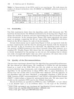
As Table 7-2 points out, one main advantage that full-duplex connections have
over half-duplex ones is that full-duplex connections do not experience collisions.
Basically, the transmit circuit on one side is wired to the receive circuit on the other
side, and vice versa. In this situation, the NIC (network interface controller), or
Ethernet card, disables the collision detection mechanism, since it isn’t needed. Full-
duplex connections are supported with the following media types: 10BaseT, 100BaseTX,
100BaseTX, 100BaseFX, and Gigabit Ethernet. Connections using 10Base5, 10BaseFL,
and 10Base2 support only half-duplexing. Please note that some older 10BaseT NICs
may not support full-duplex. An example of this is the 10BaseT interfaces on Cisco 2500
series routers.
When dealing with bridges and switches, bridges support only half-duplex
connections, while most switches support both. For instance, the 1900 and 2950
switches support both connection types. Most switches will autosense the duplexing
and appropriately configure it.
CERTIFICATION OBJECTIVE 7.02
Functions of Bridging and Switching
With all of these differences between bridges and switches, they are still, at heart, both
layer-2 devices and perform the same three basic network functions:
■
Learning They learn what device is connected to which port.
■
Forwarding They intelligently switch frames to the port or ports where the
destination is located.
■
Removing layer-2 loops They remove loops with the Spanning Tree
Protocol (STP), so that frames don’t continually circle around the network.
These functions are functions of transparent bridges. There are other types of bridging,
including source route bridging, source route transparent bridging, and source route
Half-Duplex Full-Duplex
Send and/or receive Send or receive Send and receive
Connection type Hub, 10Base2, 10Base5 Point-to-point
Collisions Yes No
TABLE 7-2
Half-Duplex
and Full-Duplex
Comparison
D:\omh\CertPrs8\934-9\ch07.vp
Monday, August 04, 2003 11:53:05 AM
Color profile: Generic CMYK printer profile
Composite Default screen
translational bridging, that appear in mixed media networks, such as Ethernet, Token
Ring, and FDDI. However, since the CCNA exam focuses on transparent bridging,
and Token Ring and FDDI are, for the most part, dead technologies, this book focuses
on transparent bridging.
The term transparent appropriately describes a transparently bridged network: the
devices connected to the network are unaware that the bridge, or switch, is a part of
the network and is forwarding frames to destinations. Basically, transparent-bridge
networks physically look like a bunch of stars connected together. However, transparent
bridges give the appearance to connected devices that every device in the broadcast
domain is on the same logical segment, as shown in Figure 7-1.
The following sections cover the three main
functions of transparent bridges and switches in
more depth. As you go through these sections, I’ll
be using the term switch to describe the layer-2
device; however, the terms bridge and switch are
interchangeable when it comes to the three main
functions.
Learning Function
One of the three main functions of a transparent switch is to learn which device is
connected to each of the active ports of the switch. As a frame comes into the port of
a switch, the switch examines the source MAC address of the frame and compares it to
its switch table, commonly referred to as a CAM (content addressable memory) table
or port address table. In the old days of bridging, CAM was a special form of high-speed
Functions of Bridging and Switching
7
CertPrs8 / CCNA Cisco Certified Network Associate Study Guide / Deal / 222934-9 / Chapter 7
FIGURE 7-1
Physical and
logical descriptions
of a transparently
bridged network
The three main functions
of a bridge/switch are learn, forward, and
remove loops.
D:\omh\CertPrs8\934-9\ch07.vp
Monday, August 04, 2003 11:53:06 AM
Color profile: Generic CMYK printer profile
Composite Default screen
memory to facilitate the switching function in a bridge when it had to forward a frame
out the correct destination port. Today, switches use RAM to store the MAC addresses,
but the term CAM is still commonly used.
When the switch receives a frame on a port, and as it examines the source MAC
address in the frame and doesn’t see a corresponding entry in the CAM table, the
switch will add the address to the table, including the source port number. If the address
is already in the CAM table, the switch compares the incoming port with the port
already in the table. If they are different, the switch updates the CAM table with the
new port information. This is important because you might have moved the device from
one port to another port, and you want the switch to learn where the new location
is and have the switch forward frames to the device correctly (not to the old port).
Anytime the switch updates an entry in the CAM table, the switch also resets the
timer for the specific entry. Switches use timers to age out old information in the CAM
table, allowing room for new addresses. Each switch has different default timers for
the aging process. Aging is important because once a CAM table is full, the switch
will not be able to learn any new addresses. A switch will also reset the timer for an
entry in the CAM table if it sees traffic from a source MAC address that is in the CAM
table. In this manner, devices that are constantly sending information will always
remain in the CAM table and devices that are not sending traffic will eventually be
aged out of the table (removed from the table).
The CAM table can be built statically or dynamically. By default, when you turn
on a switch, the CAM table is empty unless you have configured a static entry in it.
As traffic flows through the switch, the switch will begin building its CAM table. This
dynamic building process is a very nice feature. In the old days of bridging, there used
to be two kinds of bridges: learning and non-learning. Learning bridges function as
I have just described—they dynamically learn addressing locations by examining the
source MAC addresses in the Ethernet frames.
Non-learning bridges, by contrast, do not have
a dynamic learning function. Instead, you must
statically configure each device’s MAC address
and the port it is connected to. Of course, if you
had 1,000 devices in your non-learning bridged
network, you would be very busy building and
maintaining this table, which would be an
arduous task. Today, switches support both
functions. Normally, you would use static
configurations for security purposes. The discussion of static configurations is done
in the later section “MAC Address and Port Security.”
8
Chapter 7: Bridging and Switching
CertPrs8 / CCNA Cisco Certified Network Associate Study Guide / Deal / 222934-9 / Chapter 7
Bridges place learned
source MAC addresses and their
corresponding ports in a CAM or
port address table. This feature is
used to intelligently forward frames.
D:\omh\CertPrs8\934-9\ch07.vp
Monday, August 04, 2003 11:53:06 AM
Color profile: Generic CMYK printer profile
Composite Default screen
Forwarding Function
The second major function of a switch is to forward traffic intelligently. Whenever a
frame comes into a port on the switch, the switch not only examines the source MAC
address so that it can perform its learning function, it also examines the destination
MAC address to perform its forwarding function. It examines the destination MAC
address and compares this address to the addresses in its CAM table to determine which
interface it should use when forwarding the frame to the destination.
If the destination address is found in the CAM table, the forwarding process is easy:
the switch forwards the frame out the port for the corresponding CAM entry. If the
switch examines the destination address and finds that the destination is associated
with the same port as the source of the frame, the switch will drop the frame. In this
situation, you might have a hub connected to this port of the switch, and both the
source and destination are connected to this hub. Given this, the switch shouldn’t
forward any frames between these two machines to other switch segments, since this
would be wasting bandwidth in your network. As you can see, the switch is intelligently
forwarding traffic.
Frame Types
There are three different destination types: unicast, broadcast, and multicast. Depending
on the type of destination address, there are certain situations where the switch will
have to flood the frame out all of its ports (with the exception of the port the frame
was received on). Here are the three frame types that are always flooded:
■
Broadcast address Destination MAC address of FFFF.FFFF.FFFFF
■
Multicast address Destination MAC addresses between 0100.5E00.0000
and 0100.5E7F.FFFF
■
Unknown unicast destination MAC addresses The MAC address is not
found in the CAM table
With a unicast, the source device sends a separate copy of each frame to each
destination. So, as an example, if the switch needs to send the same information
to 50 different destinations, the device would have to create 50 frames, with 50
different destination MAC addresses. When a switch receives a frame with a unicast
address as the destination, the switch looks for the address in its CAM table in order
to make a switching decision. If the switch doesn’t have the address in its CAM table,
the switch will flood the frame out all of its other ports.
Functions of Bridging and Switching
9
CertPrs8 / CCNA Cisco Certified Network Associate Study Guide / Deal / 222934-9 / Chapter 7
D:\omh\CertPrs8\934-9\ch07.vp
Monday, August 04, 2003 11:53:06 AM
Color profile: Generic CMYK printer profile
Composite Default screen
It’s important to remember that you are dealing with a transparent bridge when
dealing with the forwarding process. Therefore, if the switch doesn’t know where the
destination is, and obviously the source is assuming that the device is on same the
“logical” segment, the switch will have to flood the frame to ensure that the destination,
if it is somewhere in the broadcast domain, will receive the source’s frame. This process,
hopefully, won’t happen every time. When the destination receives the frame, the
destination will probably send a response frame to the source. Through the switch’s
learning process, it now knows where the destination is located, and any further frames
sent from the source to the destination can be intelligently forwarded instead of flooded.
One issue with this process, however, is that if your CAM table is filled to capacity
and your switch can’t add new entries to the table, the switch will always flood traffic
to these destinations that it couldn’t fit into the CAM table. Therefore, it is very
important that when you buy a switch, you buy one that will be able to handle the
number of devices that you’ll have in your switched network. You’ll be creating problems
if you have 2,000 devices in your switched network but your CAM table on each switch
can hold only 1,000 entries. In this situation, the switches will be flooding traffic for
half of the destinations, creating serious bandwidth and performance problems in your
network.
A broadcast is a frame that is sent to all devices in a broadcast domain. As an example,
if a source device needed to send the same information to 50 destinations, the source
would create only one frame, and every destination would process this frame using
the destination MAC address of FFFF.FFFF.FFFF. Remember to think of the switched
network as a logical bus, where it appears that everyone is on the same piece of wire.
Therefore, when a switch receives a broadcast, it needs to ensure that all machines
will receive it, and thus the switch will flood this frame to make sure all devices receive
the broadcast.
A multicast is a frame sent to a group of devices, where the group consists of devices
interested in the receiving the multicast stream. This group can contain no devices,
all devices, or some devices in the broadcast domain. The problem of using unicast
frames to disseminate certain types of information is that it can negatively impact
the performance of your network. For instance, imagine that you have a network
where ten devices wish to receive a specific multicast stream, like a real-time video
presentation. One solution would be to have the multicast server use unicasts and
send ten copies of the same information to each destination. Of course, if the multimedia
stream is running at 5 Mbps, then this would require the server to generate 50 Mbps
worth of traffic.
Another solution would be to use a broadcast. In this situation, the multicast
server generates only one stream of information. The problem with this is that the
switched infrastructure would flood this traffic to every destination, including the
ten devices that are interested in seeing it. This solution wastes a lot of bandwidth.
10
Chapter 7: Bridging and Switching
CertPrs8 / CCNA Cisco Certified Network Associate Study Guide / Deal / 222934-9 / Chapter 7
D:\omh\CertPrs8\934-9\ch07.vp
Monday, August 04, 2003 11:53:06 AM
Color profile: Generic CMYK printer profile
Composite Default screen
The third solution is to use multicast frames.
With multicasting, switches can learn which
devices want to receive multicast traffic, and
therefore forward the multicast frames to only
those devices that want to see the multicast
traffic. This topic is beyond the scope of this
book, but it is covered in Cisco’s Switching
exam for the CCNP and CCDP certifications.
If you have a large multicast solution deployment, you will definitely want
to make sure that your switches supported advanced multicast features that
allow them to intelligently forward multicast traffic instead of having to flood
it. You want to have the switch forward multicast frames to end-stations that
are running a multicast application that need to see them—you don’t want
your switch to flood multicasts to all end-stations.
Example
To better understand what happens when a switch forwards rather than floods, take a
look at an example shown in Figure 7-2. This example shows a hub and a switch, with
various PCs connected to these two devices.
Let’s assume that the switch was just turned on, which means that its CAM
table is empty. PC-A generates a frame destined for PC-C. When the switch
receives the frame, it looks in its CAM table and does not see the source MAC
address (0000.0A01.AAAA), so it adds it along with port 1. It also examines the
destination MAC address (0000.0A01.CCCC) and does not see this address in its
CAM table, so the switch floods the frame out all of its remaining ports: 2, 3, and 4.
In this example, the switch did not need to do this because PC-C is connected to
the same hub as PC-A; however, the switch doesn’t know this yet. This is an example
of flooding an unknown destination unicast address. Figure 7-3 shows an example of
the switch adding the entry to its CAM table and flooding the frame. You can see from
this figure that the switch now has one entry in its CAM table (PC-A’s) as well as the
flooding process that it was performed. Since the destination, PC-C, is connected to
the same hub as PC-A, it obviously receives the frame.
PC-C now responds back to PC-A with a unicast frame: the source MAC address
is 0000.0A01.CCCC and the destination MAC address is 0000.0A01.AAAA. The
switch performs its learning process, and since PC-C’s MAC address is not in its
CAM table, it adds it, as is shown in Figure 7-4. Now the switch has two entries in
its CAM table: PC-A’s and PC-C’s. To perform the forwarding process, the switch
examines the destination MAC address, 0000.0A01.AAAA. It finds a match in its
Functions of Bridging and Switching
11
CertPrs8 / CCNA Cisco Certified Network Associate Study Guide / Deal / 222934-9 / Chapter 7
The three types of frames
that are always flooded by bridges and
switches are multicasts, broadcasts,
and unknown destination unicasts.
D:\omh\CertPrs8\934-9\ch07.vp
Monday, August 04, 2003 11:53:06 AM
Color profile: Generic CMYK printer profile
Composite Default screen
12
Chapter 7: Bridging and Switching
CertPrs8 / CCNA Cisco Certified Network Associate Study Guide / Deal / 222934-9 / Chapter 7
FIGURE 7-3
Adding PC-A’s MAC address to the CAM table
FIGURE 7-2
Transparent bridge forwarding example
D:\omh\CertPrs8\934-9\ch07.vp
Monday, August 04, 2003 11:53:06 AM
Color profile: Generic CMYK printer profile
Composite Default screen
CAM table and finds that the destination MAC address is associated with the same
port as the source MAC address. Therefore, the switch drops the frame: It does not
forward it out of any of its ports, as can be seen from Figure 7-4.
PC-B now sends a unicast frame to PC-F: These PCs are connected to different
ports of the switch. When the switch receives the frame from PC-B, it again performs its
learning process. Since PC-B is not in its CAM table, Switch A adds 0000.0A01.BBBB
along with port 1 to its table. Now the switch performs its forwarding function: Since
the destination MAC address 0000.0A01.FFFF is not in the CAM table, the switch
floods the frame. This process can be seen in Figure 7-5.
The switch now has three MAC addresses in its CAM table. PC-F receives the
frame and responds with an answer to PC-B. The switch again performs its learning
function: since 0000.0A01.FFFF is not in its CAM table, it adds it. Now the switch
performs its forwarding function. It sees 0000.0A01.BBBB in its CAM table with the
port number of 1 and therefore forwards the frame out of port 1 only. This process can
be seen in Figure 7-6.
In this last example, PC-E generates a broadcast (FFFF.FFFF.FFFF). When
the switch receives the broadcast frame, it performs its learning function by
adding 0000.0A01.EEEE to its CAM table. The switch then floods the frame,
since it is a broadcast. This process can be seen in Figure 7-7.
Functions of Bridging and Switching
13
CertPrs8 / CCNA Cisco Certified Network Associate Study Guide / Deal / 222934-9 / Chapter 7
FIGURE 7-4
Adding PC-C’s MAC address to the CAM table
D:\omh\CertPrs8\934-9\ch07.vp
Monday, August 04, 2003 11:53:07 AM
Color profile: Generic CMYK printer profile
Composite Default screen
14
Chapter 7: Bridging and Switching
CertPrs8 / CCNA Cisco Certified Network Associate Study Guide / Deal / 222934-9 / Chapter 7
FIGURE 7-5
Adding PC-B’s MAC address to the CAM table
FIGURE 7-6
Forwarding PC-F’s traffic out of Port 1 only
D:\omh\CertPrs8\934-9\ch07.vp
Monday, August 04, 2003 11:53:07 AM
Color profile: Generic CMYK printer profile
Composite Default screen
From this simple example, you can see the role of the switch is not a complicated
one. First, the switch examines the source MAC address in the frame and updates the
CAM table if necessary. Second, the switch examines the destination MAC address
in the frame and makes a forwarding decision. As you will see in the next section, the
switch’s function becomes more complicated when there is more than one bridge in
the network, and there are layer-2 loops between the bridges.
Loops
At the backbone of your network, or at least where you have critical resources, you’ll
probably incorporate some type of redundancy in your design. This might include
redundancy with your switches at layer-2, creating layer-2 loops in your network as is
shown in Figure 7-8. The problem with loops in your network is that when the switch
floods certain types of traffic, such as broadcasts or multicasts, you don’t want this traffic
going around and around the loop forever, creating high utilization problems.
Plus, for unknown destinations, as the frame is going around the loop, the
switches update their CAM tables with the source address, which eventually shows
up as connected to another connected switch, creating confusion about where the
Functions of Bridging and Switching
15
CertPrs8 / CCNA Cisco Certified Network Associate Study Guide / Deal / 222934-9 / Chapter 7
FIGURE 7-7
PC-E generates a broadcast
D:\omh\CertPrs8\934-9\ch07.vp
Monday, August 04, 2003 11:53:07 AM
Color profile: Generic CMYK printer profile
Composite Default screen
source device really is located. For example, if a device is connected to Switch 3, when
the device generates a frame, Switch 3 adds the source MAC address to its CAM table
and notes that it is connected to the incoming port. If Switch 3 doesn’t know where
the destination is located, it will flood the frame to Switches 1 and 2 on its two uplink
ports. If both Switches 1 and 2 don’t know where the destination is, they also flood
the frame across the link between them, and then will flood it back to Switch 3. This
presents a problem: When Switch 3 receives these flooded frames and performs its
learning function, it now looks as if the device is connected to not the original port,
but one of the two uplink ports to Switch 1 or 2.
The Spanning Tree Protocol (STP) is used to prevent these problems from occurring.
STP removes loops in your network but still allows for redundancy. Actually, the loop
removal process is done in software—you don’t have to physically disconnect wires
between your switches to remove the loops. The following section covers the basics
of STP.
CERTIFICATION OBJECTIVE 7.03
The Spanning Tree Protocol
The main function of the Spanning Tree Protocol (STP) is to remove layer-2 loops from
your topology. DEC, now a part of Compaq/HP, originally developed STP. IEEE enhanced
the initial implementation of STP, giving us the 802.1d standard. The two different
implementations of STP, DEC and 802.1d, are not compatible with each other—you
need to make sure that all of your devices either support one or the other. All of Cisco’s
16
Chapter 7: Bridging and Switching
CertPrs8 / CCNA Cisco Certified Network Associate Study Guide / Deal / 222934-9 / Chapter 7
FIGURE 7-8
Looped layer-2
topology
D:\omh\CertPrs8\934-9\ch07.vp
Monday, August 04, 2003 11:53:08 AM
Color profile: Generic CMYK printer profile
Composite Default screen
switches use IEEE’s 802.1d protocol, which is enabled, by default, on the switches. If
you have a mixed-vendor environment where some devices are running 802.1d and
others are running DEC’s STP, then you may run into layer-2 looping problems.
Bridge Protocol Data Units
For STP to function, the switches need to share information. What they share are bridge
protocol data units (BPDUs), which are sent out as multicast information that only other
layer-2 devices are listening to. Switches will use BPDUs to learn the topology of the
network: what device is connected to other devices, and if there are any layer-2 loops
based on this topology.
If any loops are found, the switches will disable a port or ports in the topology to
ensure that there are no loops. In other words, from one device to any other device
in the switched network, only one path can be taken. If there are any changes in the
layer-2 network, such as when a link goes down, a new link is added, a new switch
is added, or a switch fails, the switches will share this information, causing the STP
algorithm to be re-executed and a new loop-free topology is created.
BPDUs are sent out every two seconds. This helps speed up convergence. Convergence
is a term used in networking to describe the amount of time it takes to deal with changes
and have the network back up and running. The shorter the time period to find and
fix problems, the quicker your network is back on line. Setting the BPDU advertisement
time to two seconds allows changes to be very quickly shared with all the other switches
in the network, reducing the amount of time any disruption would create.
BPDUs contain a lot of information to help the switches determine the topology
and any loops that result from that topology. For instance, each bridge has a unique
identifier, called a bridge or switch ID. This is typically the priority of the switch and
the MAC address of the switch itself. When switches advertise a BPDU, they place
their switch ID in the BPDU so that a receiving switch can tell which switches it is
receiving topology information from. The following sections cover the steps that occur
while STP is being executed in a layer-2 network.
The Spanning Tree Protocol
17
CertPrs8 / CCNA Cisco Certified Network Associate Study Guide / Deal / 222934-9 / Chapter 7
Most bridges and switches
use IEEE’s 802.1d protocol to remove
loops. BPDUs are used to share information,
and these are sent out as multicasts every
two seconds. The BPDU contains
the bridge’s or switch’s ID, made up
of a priority value and the its MAC
address.
D:\omh\CertPrs8\934-9\ch07.vp
Monday, August 04, 2003 11:53:08 AM
Color profile: Generic CMYK printer profile
Composite Default screen
Root Bridge
The term Spanning Tree Protocol describes the process that is used. The STP algorithm
is similar to how link state routing protocols, such as OSPF, ensure that no layer-3 loops
are created. (Link state routing protocols are discussed in Chapters 9 and 11.) A spanning
tree is first created. Basically, a spanning tree is an inverted tree. At the top of the tree
is the root, or what is referred to in STP as the root bridge or switch. From the root switch,
there are branches (physical Ethernet connections) connecting to other switches, and
branches from these switches to other switches, and so on.
Take a look at a physical topology of a network to demonstrate a spanning tree,
shown in Figure 7-9. When STP is run, a logical tree structure is built, like that shown
in Figure 7-10. As you can see from Figure 7-10, SwitchA is the root switch and is
at the top of the tree. Underneath it are two branches connecting to SwitchB and
SwitchC. These two switches are connected to SwitchE, creating a loop. SwitchB is
also connected to SwitchD. At this point, STP is still running, and a loop still exists.
As STP runs, the switches will determine, out of the four switches, SwitchA, SwitchB,
SwitchC, and SwitchE, which port on these switches will be disabled in software in
order to remove the loop.
Actually, the very first step in STP is to elect the root switch. BPDUs are used for
the election process. As was mentioned earlier, when a device advertises a BPDU, it
puts its switch ID in the BPDU. The switch ID is used to elect the root switch. The
18
Chapter 7: Bridging and Switching
CertPrs8 / CCNA Cisco Certified Network Associate Study Guide / Deal / 222934-9 / Chapter 7
FIGURE 7-9
Physical layer-2
looped topology
D:\omh\CertPrs8\934-9\ch07.vp
Monday, August 04, 2003 11:53:08 AM
Color profile: Generic CMYK printer profile
Composite Default screen
switch with the lowest switch ID is chosen as root. The switch ID is made up of two
components:
■
The switch’s priority, which defaults to 32,768 on Cisco switches (two bytes
in length)
■
The switch’s MAC address (six bytes in length)
With Cisco’s switches, the default priority is 32,768, which is defined by IEEE 802.1d.
Assuming that all your switches are Cisco switches, the switch with the lowest MAC
address will be chosen as the root switch. You can override the election process by
changing the priority value assigned to a switch. If you want one switch to be the root,
assign it a priority value that is lower than 32,768. Through the sharing of the BPDUs,
the switches will figure out which switch has the lowest switch ID, and that switch is
chosen as the root switch. Please note that this election process is taking place almost
simultaneously on each switch, where each switch will come up with the same result.
For Catalyst switches that implement VLANs (which are discussed in Chapter 8),
the switches will have a different switch ID per VLAN, and a separate instance of STP
per VLAN. Each VLAN has its own root switch (which can be the same switch for
all VLANs, or different switches for each VLAN). And within each VLAN, STP will
run and remove loops in that particular VLAN. Cisco calls this concept per-VLAN
STP (PVST). This topic is beyond the scope of this chapter but is covered in Cisco’s
Switching exam for the CCNP and CCDP certifications.
The Spanning Tree Protocol
19
CertPrs8 / CCNA Cisco Certified Network Associate Study Guide / Deal / 222934-9 / Chapter 7
FIGURE 7-10
Logical layer-2
STP topology
D:\omh\CertPrs8\934-9\ch07.vp
Monday, August 04, 2003 11:53:08 AM
Color profile: Generic CMYK printer profile
Composite Default screen
This election process of the root switch takes
place each time there is a topology change in the
network, such as the root switch failing, or the
addition of a new switch. All the other switches
in the layer-2 topology expect to see BPDUs from
the root switch within the maximum age time,
which defaults to 20 seconds. If the switches don’t
see a BPDU message from the root within this period, they assume that the root switch
has failed and will begin a new election process to choose a new root bridge.
Root Port
After the root switch is elected, every other switch in the network needs to choose a
single port on itself that it will use to reach the root. This port is called the root port. For
some switches, like SwitchD in Figure 7-10, this is very easy—it has only one port it can
use to access the switched topology. However, other switches, like SwitchB, SwitchC,
and SwitchE in Figure 7-10, might have two or more ports that they can use to reach
the root switch. If there are multiple ports to choose from, an intelligent method needs
to be used to choose the best port. With STP, there are a few factors that are taken into
consideration when choosing a root port. It is important to point out that the root switch
itself will never have a root port—it’s the root, so it doesn’t need a port to reach itself.
First, each port is assigned a cost, called a port cost. The lower the cost, the more
preferable the port is. The cost is an inverse reflection of the bandwidth of the port.
There are actually two sets of costs for 802.1d’s implementation of STP—one for the
old method of calculation and one for the new, as is shown in Table 7-3. Cisco’s 1900
switch uses the old 802.1d port cost values, while Cisco’s other switches, including
the 2950, 3500, 3550, 4000, 5500, 6000, and 6500 switches, use the newer cost values.
Switches always prefer lower-cost ports over higher-cost ones. Each port also has a
priority assigned to it, called a port priority value, which defaults to 32. Again, switches
will prefer a lower priority value over a higher one.
20
Chapter 7: Bridging and Switching
CertPrs8 / CCNA Cisco Certified Network Associate Study Guide / Deal / 222934-9 / Chapter 7
The switch with the lowest
switch (bridge) ID is chosen as the root
switch.
Connection Type New Cost Value Old Cost Value
10Gb 2 1
1Gb 4 1
100Mb 19 10
10Mb 100 100
TABLE 7-3
Port Costs
for STP
D:\omh\CertPrs8\934-9\ch07.vp
Monday, August 04, 2003 11:53:08 AM
Color profile: Generic CMYK printer profile
Composite Default screen
One of the main reasons for replacing the old cost method with a newer one is the
inherent weakness in the algorithm used to calculate the port cost: 1,000 divided by
the port speed. The assumption was that no port would have a speed greater than 1 Gbps
(1,000 Mbps). As you can see from today’s Ethernet standards, 10 Gbps is slowly making
its way into corporate networks. With the old port cost method, 1 Gbps and 10 Gbps
links are treated as having the same speed.
Path costs are calculated from the root switch. A path cost is basically the accumulated
port costs from a switch to the root switch. When the root advertises BPDUs out of
its interfaces, the default path cost value in the BPDU is 0. When a connected switch
receives this BPDU, it increments the path cost by the cost of the incoming port. If the
port was a Fast Ethernet port, then the path cost would be: 0 (the root’s path cost) + 19
(the switch’s port cost) = 19. This switch, when it advertises BPDUs to switches
behind it, will include the updated path cost. As the BPDUs propagate further and
further from the root switch, the path costs become higher and higher.
Remember that path costs are incremented as a BPDU comes into a port, not
when a BPDU is advertised out of a port.
If a switch has two or more choices of paths to reach the root, it needs to choose
one path and thus have one root port. Here are the STP steps a switch will go through
when choosing a root port:
1. Choose the path with the lowest accumulated path cost to the root if there is
a choice between two or more paths to reach the root.
2. If there is a tie between port priorities, choose the neighboring switch (that
your switch would go through to reach the root) with the lowest switch ID value.
3. If you have multiple paths, and they all go through the same neighboring switch,
choose the port with the lowest priority value.
4. If the priority values are the same between the ports, choose the physically
lowest-numbered port on the switch (on a 1900, that would be Ethernet 0/1).
After going through this selection process, the switch will have one, and only one,
port that it will be its root port.
Designated Port
The last section discussed how each switch has a single root port that it uses to reach
the root switch. Besides each switch having a root port, each segment also has a single
The Spanning Tree Protocol
21
CertPrs8 / CCNA Cisco Certified Network Associate Study Guide / Deal / 222934-9 / Chapter 7
D:\omh\CertPrs8\934-9\ch07.vp
Monday, August 04, 2003 11:53:08 AM
Color profile: Generic CMYK printer profile
Composite Default screen
port that is uses to reach the root. This port is called a designated port. For instance,
imagine that there is a segment with two switches connected to it. Either one or the
other switch will forward traffic from this segment (a LAN connection) to the rest of
the network.
The third step in running STP is to elect a designated port on a single switch for
each segment in the network. The switch (and its port) that is chosen should have the
best path to the root switch. Here are the steps that are taken by switches in determining
which port on which switch will be chosen as the designated port.
1. The connected switch on the segment with the lowest accumulated path cost
to the root bridge will be used.
2. If there is a tie in accumulated path costs between two switches, then the
switch with the lowest switch ID will be chosen.
3. If it happens that it is the same switch, but with two separate connections
to the LAN segment, the switch port with the lowest priority is chosen.
4. If there is still a tie (the priorities of the ports on this switch are the same),
then the physically lowest numbered port on the switch is chosen.
After going through these steps for each segment, each segment will have a single
designated port that it will use to reach the root switch. Sometimes the switch that
contains the designated port is called a designated switch. This term is misleading, since
it is a port on the switch that is responsible for forwarding traffic. There may be two
segments a switch is connected to, but it may be the designated switch for only one
of those segments; another switch may provide the designated port for the second
segment.
Interestingly enough, every active port on the root switch is a designated port.
This makes sense because the cost of the attached network segments to reach the
root is 0, the lowest accumulated cost value. In other words, each of these LAN
segments is directly attached to the root switch, so in reality, it costs nothing for
the segment to reach the root switch itself.
Port States
There are five different states that a port can be in when it is participating in STP:
■
Blocked
■
Listening
■
Learning
22
Chapter 7: Bridging and Switching
CertPrs8 / CCNA Cisco Certified Network Associate Study Guide / Deal / 222934-9 / Chapter 7
D:\omh\CertPrs8\934-9\ch07.vp
Monday, August 04, 2003 11:53:09 AM
Color profile: Generic CMYK printer profile
Composite Default screen
■
Forwarding
■
Disabled
Of the five states, only the first four are used when the algorithm is running.
The following sections cover the different port states for STP.
Blocking
Ports will go into a blocking state under one of three conditions:
■
Election of a root switch (for instance, when you turn on all the switches
in a network)
■
When a switch receives a BPDU on a port that indicates a better path to
the root switch than the port the switch is currently using to reach the root
■
If a port is not a root port or a designated port
A port in a blocked state will remain there for 20 seconds by default (the maximum
age timer). During this state, the port is only listening to and processing BPDUs on
its interfaces. Any other frames that the switch receives on a blocked port are dropped.
In a blocking state, the switch is attempting to figure out which port is going to be the
root port, which ports on the switch need to be designated ports, and which ports will
remain in a blocked state to break up any loops. After the 20 seconds have expired,
the port will then move to the listening state.
Listening
After the 20-second timer expires, a root port or a designated port will move to a listening
state. Any other port will remain in a blocked state. During the listening state, the port
is still listening for BPDUs and double-checking the layer-2 topology. Again, the only
traffic that is being processed in this state consists of BPDUs; all other traffic is dropped.
A port will stay in this state for the length of the forward delay timer. The default for this
value is 15 seconds.
Learning
From a listening state, a port moves into a learning state. During the learning state, the
port is still listening for and processing BPDUs on the port; however, unlike while in the
listening state, the port begins to process user frames. When processing user frames,
the switch is examining the source addresses in the frames and updating its CAM table,
but the switch is still not forwarding these frames out destination ports. Ports stay in
this state for the length of the forward delay time (which defaults to 15 seconds).
The Spanning Tree Protocol
23
CertPrs8 / CCNA Cisco Certified Network Associate Study Guide / Deal / 222934-9 / Chapter 7
D:\omh\CertPrs8\934-9\ch07.vp
Monday, August 04, 2003 11:53:09 AM
Color profile: Generic CMYK printer profile
Composite Default screen
Forwarding
Finally, after the forward delay timer expires, ports that were in a learning state are
placed in a forwarding state. In a forwarding state, the port will process BPDUs, update
its CAM table with frames that it receives, and forward user traffic through the port.
Disabled
The disabled state is a special port state. A port in a disabled state is not participating
in STP. This could be because the port has been manually shut down by an administrator,
manually removed from STP, disabled because of security issues, or rendered nonfunctional
because of a lack of a physical-layer signal (such as the patch cable being unplugged).
Layer-2 Convergence
As you have noticed in the last section, STP goes through a staged process, which slows
down convergence. For switches, convergence occurs once STP has completed: a root
switch is elected, root and designated ports have been chosen, the root and designated
ports have been placed in a forwarding state, and all other ports have been placed in a
blocked state.
If a port has to go through all four states, convergence takes 50 seconds: 20 seconds
in blocking, 15 seconds in listening, and 15 seconds in learning. If a port doesn’t have
to go through the blocking state but starts at a listening state, convergence takes
only 30 seconds. This typically occurs when the root port is still valid, but another
topology change has occurred. Remember that during this time period (until the port
reaches a forwarding state), no user traffic is forwarded through the port. So, if a user
was performing a telnet session, and STP was being recalculated, the telnet session,
from the user’s perspective, would appear stalled, or the connection would appear lost.
Obviously, a user will notice this type of disruption.
Therefore, the faster that convergence takes place, the less disruption that this will
cause for your users. You can reduce the two timers to reduce your convergence time,
24
Chapter 7: Bridging and Switching
CertPrs8 / CCNA Cisco Certified Network Associate Study Guide / Deal / 222934-9 / Chapter 7
There are four major
port states in STP: blocking (20 seconds),
listening (15 seconds), learning (15 seconds),
and forwarding. It can take 30–50 seconds
for STP convergence to take place.
In blocking and listening states, only
BPDUs are processed. In a learning
state, the CAM table is being built.
In a forwarding state, user frames
are moved between ports.
D:\omh\CertPrs8\934-9\ch07.vp
Monday, August 04, 2003 11:53:09 AM
Color profile: Generic CMYK printer profile
Composite Default screen
but this can create more problems if you aren’t aware of what you are doing when you
change them. For user ports, you can use the PortFast feature to speed up convergence.
PortFast should be used only on ports that will not create layer-2 loops, such as ports
connected to PCs, servers, and routers (sometimes referred to as a user, or edge, ports).
A port with PortFast enabled is always placed in a forwarding state—this is even
true whenever STP is running and the root and designated ports are going through
their different states. So, when STP is running,
PortFast ports on the same switch can still
forward traffic among themselves, limiting your
STP disruption somewhat. However, if these
devices wanted to talk to devices connected to
other switches, they would have to wait until
STP completed and the root and designated
ports had moved into a forwarding state.
Rapid Spanning Tree Protocol
The 802.1d standard was designed back when waiting for 30–50 seconds for convergence
wasn’t a problem. However, in today’s networks, this can cause serious performance
problems for networks that use real-time applications, like Voice over IP (VoIP). To
overcome these issues, Cisco developed proprietary bridging features called PortFast
(discussed in the last section), UplinkFast, and BackboneFast. The problem with these
features is that they are proprietary to Cisco.
The Rapid Spanning Tree Protocol (RSTP) is an IEEE standard, 802.1w, that is
interoperable with 802.1d and an extension to it. With RSTP, there are only three port
states: discarding, learning, and forwarding. A port in a discarding state is basically
the grouping of 802.1d’s blocking, listening, and disabled states. The following sections
cover some of the enhancements included in RSTP.
Additional Port Roles
With RSTP, there are still root and designated ports, performing the same roles as
those in 802.1d. However, RSTP adds two additional port types: alternate ports and
backup ports. These two ports are similar to the ports in a blocking state in 802.1d.
An alternate port is a port that has an alternative path or paths to the root but is currently
in a discarding state. A backup port is a port on a segment that could be used to reach
the root port, but there is already an active designated port for the segment. The best
way to look at this is that an alternate port is a secondary, unused root port, and a
backup port is a secondary, unused designated port.
The Spanning Tree Protocol
25
CertPrs8 / CCNA Cisco Certified Network Associate Study Guide / Deal / 222934-9 / Chapter 7
STP convergence has
occurred when all root and designated
ports are in a forwarding state and all
other ports are in a blocking state.
D:\omh\CertPrs8\934-9\ch07.vp
Monday, August 04, 2003 11:53:09 AM
Color profile: Generic CMYK printer profile
Composite Default screen