Tài liệu Routing and Switching Alogrithms pdf
Bạn đang xem bản rút gọn của tài liệu. Xem và tải ngay bản đầy đủ của tài liệu tại đây (646.69 KB, 64 trang )
1
○○○○○○○○○○○○○○○○○○○○○○○○○○○○○○○○○○○○○○○○○○○○○○○○
6
Routing and
Switching Alogrithms
Terms you’ll need to understand:
✓ Distance vector protocols
✓ Routing Information Protocol (RIP)
✓ Interior Gateway Routing Protocol (IGRP)
✓ Enhanced Interior Gateway Routing Protocol (EIGRP)
✓ Link-state protocols
✓ Intermediate System to Intermediate System (ISIS)
✓ Open Shortest Path First (OSPF)
✓ Hello packets
✓ Border Gateway Protocol (BGP)
✓ Interior Border Gateway Protocol (IBGP)
✓ Exterior Border Gateway Protocol (EBGP)
✓ Summarization
✓ Multicast
Techniques you’ll need to master:
✓ Describing the mechanics of RIP, IGRP, EIGRP, ISIS,
OSPF, and BGP
✓ Setting up IP routing protocols in a simple design
scenario
✓ Identifying the IP routing table for each routing protocol
2
○○○○○○○○○○○○○○○○○○○○○○○○○○○○○○○○○○○○○○○○
Chapter 6
This chapter presents the commands you need to know when configuring the
various IP routing protocols on Cisco routers. Frequently, the terminology pre-
sents the most challenging aspect of understanding routing with Cisco IOS.
Therefore, after reviewing the basic CCIE blueprint objectives covered in this
chapter, we’ll offer a brief overview of basic terminology. Then, we’ll move on to
discuss the Cisco IOS routing configuration commands.
The following CCIE blueprint objectives as laid out by the Cisco Systems CCIE
program are covered in this chapter:
➤ Border Gateway Protocol (BGP)—Peer groups, route reflectors, confederations,
clusters, attributes, autonomous systems (AS), route maps, filters, neighbors,
decision algorithm, Interior Border Gateway Protocol (IBGP), Exterior Bor-
der Gateway Protocol (EBGP)
➤ Enhanced Interior Gateway Routing Protocol (EIGRP)—Metrics, mechanics,
and design
➤ Intermediate System to Intermediate System (ISIS)—Metrics, mechanics, and
design
➤ Open Shortest Path First (OSPF)—Areas, virtual links, stub, not so stubby ar-
eas (NSSA), area border router (ABR), autonomous system boundary router
(ASBR) redistributions, media dependencies, external versus internal, sum-
marization, designated router (DR), backup designated router (BDR), adja-
cencies, link-state advertisement (LSA) types, link-state database, shortest
path first (SPF) algorithm, authentication
➤ Routing Information Protocol (RIP) and RIP II—Metrics, mechanics, and
design
➤ Multicast—Design, protocol independent multicast (PIM), Distance Vector
Multicast Routing Protocol (DVMRP), Internet Group Management Pro-
tocol (IGMP)
As in other chapters in this book, additional information is provided in this chapter
for completeness and in preparation for additional subjects as the CCIE program
expands. By now, you should be aware that a CCIE candidate’s knowledge must
span a wide range of topics. One topic of particular emphasis involves under-
standing the Network layer and how Cisco devices can be used to accomplish
intelligent routing. This chapter, the largest chapter in the book, addresses these
focal-point topics to help you fully prepare for the CCIE exam.
3
○○○○○○○○○○○○○○○○○○○○○○○○○○○○○○○○○○○○○○○○
Routing and Switching Algorithms
Summary of Available IP
Routing Protocols
Cisco IOS supports a number of IP routing protocols. Listing 6.1 shows the
routing protocols supported by Cisco routers. According to the CCIE exam objec-
tives, you’re only required to understand RIP, IGRP, EIGRP, ISIS, OSPF, and
BGP.
Listing 6.1 The router ? command.
R2(config)#router ?
bgp Border Gateway Protocol (BGP)
egp Exterior Gateway Protocol (EGP)
eigrp Enhanced Interior Gateway Routing Protocol (EIGRP)
igrp Interior Gateway Routing Protocol (IGRP)
isis ISO ISIS
iso-igrp IGRP for OSI networks
mobile Mobile routes
odr On-Demand Stub Routes
ospf Open Shortest Path First (OSPF)
rip Routing Information Protocol (RIP)
static Static routes
RIP, IGRP, EIGRP, OSPF, and BGP are called dynamic protocols because they
employ techniques that “automatically” discover and learn IP routing informa-
tion from other routers. Dynamic protocols use dynamic routing, a routing method
in which routers learn about IP networks without static configuration.
In the upcoming sections, we’ll cover the distance vector protocols—RIP, RIP II,
and IGRP. Next, we’ll look at a hybrid distance vector and link-state protocol—
EIGRP. Then, we’ll cover the link-state protocols—ISIS and OSPF. Finally, we’ll
discuss BGP, a path vector protocol, which is an advanced routing protocol used
extensively in the Internet.
Routing Information Protocol (RIP) I and II
Routing Information Protocol (RIP) is a distance vector protocol, which uses
hop counts as the metric. This metric determines whether an IP network will be
placed in the routing table. There are two versions of RIP—RIP I and RIP II.
Both RIP versions I and II operate over UDP using port 520. As discussed in
Chapter 2, RIP uses holddowns, split horizon, and poison reverse to avoid rout-
ing loops. RIP version I cannot carry subnet information, and it applies the de-
fault network mask to all networks. Hence, all networks within a RIP network
must have the same subnet mask throughout. RIP II does carry subnet informa-
tion, because RIP II can use variable length subnet masking (VLSM).
4
○○○○○○○○○○○○○○○○○○○○○○○○○○○○○○○○○○○○○○○○
Chapter 6
RIP version I characteristics can be summarized as follows:
➤ Distance vector protocol
➤ Hop count is 15
➤ Broadcasts full routing table every 30 seconds
➤ RIP can load balance if the hop count is the same
RIP version II characteristics can be summarized as follows:
➤ Distance vector protocol
➤ Hop count is 15
➤ Supports VLSM (carries subnet information in updates)
➤ Authentication of IP routing updates
The deficiencies encountered in RIP I, such as no support for variable length sub-
net masks, spurred the release of RIP version II. RIP II’s biggest improvement over
RIP I is that RIP II supports variable length subnetting and authentication of
routing updates. RIP II is also a classless routing protocol, whereas RIP Version
I is classful. RIP II still has a hop count limit of 15. Furthermore, RIP II supports
multicast updates. While RIP II provides advancements over RIP I, it still con-
tains some of the deficiencies found in RIP I. For example, RIP II continues to
send full routing updates every 30 seconds and limits hop counts to 15 hops.
Cisco routers support both RIP I and RIP II. By default a Cisco router runs RIP
version I. Therefore, by default, the router will listen to RIP II updates but will
only forward RIP I updates unless configured otherwise.
Note: In order to configure RIP version II, you will have to be in the “router rip”
configuration mode.
To further clarify the operation of RIP I and RIP, let’s look at a sample RIP
configuration on a small network consisting of four Cisco routers.
Configurating RIP I and II
RIP is easy to configure, you start RIP with the IOS command router rip and
then apply the networks you want to be advertised. The IOS command to enable
the local network within RIP is:
network <classful networks to be advertised>
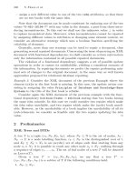
For illustrative purposes, let’s configure the network shown in Figure 6.1 for IP
RIP version I. Then, we can modify the configuration to enable RIP II.
5
○○○○○○○○○○○○○○○○○○○○○○○○○○○○○○○○○○○○○○○○
Routing and Switching Algorithms
In order to get our RIP network operating, a few steps will need to occur so let’s
briefly discuss them. First, we will need to start the RIP routing process on each
router and then apply the networks that are advertised as shown previously. The
RIP configuration on all three routers is identical because we are using the classful
Class A address of 10.0.0.0.
Listing 6.2 provides the configuration for router R1 shown in Figure 6.1. Router R1’s
RIP configuration is identical to the configuration of routers R2 through R4.
Listing 6.2 IP RIP configuration.
hostname R1
....
router rip
network 10.0.0.0
10.1.1.0/24
10.1.3.0/24
10.1.2.0/24
10.1.5.0/24
10.1.6.0/24
10.1.9.0/24
10.1.4.0/24
10.1.8.0/24
10.1.7.0/24
R1
R2
R4
R3
s2
s3
Token
Ring
s1
s0
s1
s3
s0
s1
E0
E0
s1
s0
RIP example
Router rip
network 10.0.0.0
IGRP example
Router igrp1
network 10.0.0.0
EIGRP example
Router eigrp1
network 10.0.0.0
Configuration of all
routers is the same
E0
Figure 6.1 RIP network scenario.
6
○○○○○○○○○○○○○○○○○○○○○○○○○○○○○○○○○○○○○○○○
Chapter 6
As you can see in Listing 6.2, the network uses the Class A network of 10.0.0.0.
Hence, we only need one line to identify the directly connected networks. To
view the IP routing table, you type the IOS command show ip route. Listing 6.3
shows the R1 router’s routing table.
Listing 6.3 The show ip route command.
R1#sh ip route
.....
10.0.0.0/8 is variably subnetted, 16 subnets, 2 masks
R 10.1.9.0/24 [120/4] via 10.1.4.1, 00:00:22, Serial3
R 10.1.8.0/30 [120/1] via 10.1.4.1, 00:00:22, Serial3
[120/1] via 10.1.2.2, 00:00:14, Serial2
R 10.1.8.0/24 [120/4] via 10.1.2.2, 00:00:14, Serial2
R 10.1.3.0/24 [120/5] via 10.1.4.1, 00:00:22, Serial3
R 10.1.3.0/24 [120/1] via 10.1.2.2, 00:00:14, Serial2
C 10.1.2.0/24 is directly connected, Serial2
C 10.1.1.0/24 is directly connected, Ethernet0
R 10.1.7.0/24 [120/2] via 10.1.2.2, 00:00:15, Serial2
C 10.1.7.0/24 is directly connected, Serial1
R 10.1.6.0/24 [120/4] via 10.1.4.1, 00:00:22, Serial3
R 10.1.6.0/24 [120/1] via 10.1.7.2, 00:00:13, Serial1
R 10.1.5.0/24 [120/1] via 10.1.7.2, 00:00:15, Serial1
[120/1] via 10.1.2.2, 00:00:16, Serial2
C 10.1.4.0/42 is directly connected, Serial3
R* 0.0.0.0/0 [120/1] via 10.1.4.1, 00:00:23, Serial3
Let’s examine the table shown in Listing 6.3. Each R on the left-hand side indi-
cates an entire RIP network has been learned. The C shows that the indicated
network is directly “connected” to the router displaying the routing table. The IP
network is then listed with an administrative distance (a measure of trustworthi-
ness; the lower the better) and the hop count. For example, the network 10.1.5.0/
24 is indicated by the R on the left side. Because the hop count 1 is sent via Serial
1 and Serial 2, the Cisco router will load balance across the two paths to the
remote network 10.1.5.0/30. Following this is the next hop address (10.1.7.2 or
10.1.2.2, for example, to the remote network 10.1.5.0/30) and how long the net-
work has been valid in minutes and seconds. Let’s take another remote network,
say 10.1.9.0/24, in the routing table:
R 10.1.9.0/24 [120/4] via 10.1.4.1, 00:00:22, Serial3
We’ll define the network as follows:
➤ R—The network was learned via RIP (The key is shown at the beginning of
the table.)
➤ 10.1.9.0/24—Which subnet is learned and how many bits of subnetting are
applied
7
○○○○○○○○○○○○○○○○○○○○○○○○○○○○○○○○○○○○○○○○
Routing and Switching Algorithms
➤ [120/4]—Administrative distance/hops
➤ via 10.1.4.1—The IP address of the interface that the router learned the route
from
➤ 00:00:22—How long ago was the route learned
➤ Serial3 —What interface the network has been discovered from.
As you can see in Listing 6.3, the network 10.1.5.0/24 is reachable via routers R2
and R3 with the same hop count (1) so RIP will load balance to this network
because of the multiple paths. Listing 6.3 also shows a default route. The default
route is used if there is an IP packet to an unknown destination. In Listing 6.3,
the default route will be sent to the next hop address 10.1.4.1 or router R4. Let’s
assume you have been supplied a default router from the source address
131.108.1.100. To create a default route in RIP, you use the following command:
ip route 0.0.0.0 0.0.0.0 131.108.1.100
Note: The combination of a source address of 0.0.0.0 and mask of 0.0.0.0 indicates a
special route known as a default route.
The preceding command injects a default route into any neighboring RIP rout-
ers. To view the characteristics of how RIP is operating on a Cisco router, you can
use the show ip protocol command, as illustrated in Listing 6.4.
Listing 6.4 The show ip protocol command.
R1#show ip protocol
Routing Protocol is "rip"
Sending updates every 30 seconds, next due in 21 seconds
Invalid after 180 seconds, hold down 180, flushed after 240
Outgoing update filter list for all interfaces is not set
Incoming update filter list for all interfaces is not set
Redistributing: rip
Default version control: send version 1, receive any version
Interface Send Recv Key-chain
Ethernet0 1 1 2
Serial0 1 1 2
Serial1 1 1 2
Serial2 1 1 2
Serial3 1 1 2
Routing for Networks:
10.0.0.0
Routing Information Sources:
Gateway Distance Last Update
10.1.8.1 120 00:00:13
Distance: (default is 120)
8
○○○○○○○○○○○○○○○○○○○○○○○○○○○○○○○○○○○○○○○○
Chapter 6
As you can see in Listing 6.4, the router sends updates every 30 seconds, and the
next expected update will be in 21 seconds; RIP version I packets are being sent
out on interfaces E0, S0, S1, S2, and S3; and the router is listening to both RIP I
and RIP II. The administrative distance, which is defined as a group of hosts or
routers under a common management, for RIP is 120.
For further study, let’s now change the subnet mask on all the serial links to a 30-
bit mask or 255.255.255.252. RIP I will not support variable length subnet masking
(VLSM), so we’ll turn on RIP II globally. To activate RIP II, you enter the com-
mand displayed in Listing 6.5.
Note: All serial links in Figure 6.1 have been configured with 30 bit mask. For
example, the link between R1 and R4 that was assigned the subnet 10.1.4.0/24 has
now become 10.1.4.0/30, and so forth.
Listing 6.5 Enabling RIP II.
router rip
version 2
The commands in Listing 6.5 will force the router to send and receive RIP ver-
sion II packets only. Let’s take another look at the routing table for R1 now that
RIP II is enabled for the router. Listing 6.6 shows the updated routing table.
Listing 6.6 The show ip route command after enabling RIP II.
R1#sh ip route
Gateway of last resort is 10.1.4.1 to network 0.0.0.0
10.0.0.0/8 is variably subnetted, 16 subnets, 2 masks
R 10.1.9.0/30 [120/4] via 10.1.4.1, 00:00:22, Serial3
R 10.1.9.0/24 [120/1] via 10.1.4.1, 00:00:22, Serial3
R 10.1.8.0/30 [120/1] via 10.1.4.1, 00:00:22, Serial3
[120/1] via 10.1.2.2, 00:00:14, Serial2
R 10.1.8.0/24 [120/4] via 10.1.2.2, 00:00:14, Serial2
R 10.1.3.0/30 [120/5] via 10.1.4.1, 00:00:22, Serial3
R 10.1.3.0/24 [120/1] via 10.1.2.2, 00:00:14, Serial2
C 10.1.2.0/30 is directly connected, Serial2
C 10.1.1.0/24 is directly connected, Ethernet0
R 10.1.7.0/24 [120/2] via 10.1.2.2, 00:00:15, Serial2
C 10.1.7.0/30 is directly connected, Serial1
R 10.1.6.0/30 [120/4] via 10.1.4.1, 00:00:22, Serial3
R 10.1.6.0/24 [120/1] via 10.1.7.2, 00:00:13, Serial1
R 10.1.5.0/30 [120/1] via 10.1.7.2, 00:00:15, Serial1
[120/1] via 10.1.2.2, 00:00:16, Serial2
R 10.1.5.0/24 [120/4] via 10.1.2.2, 00:00:16, Serial2
C 10.1.4.0/30 is directly connected, Serial3
R* 0.0.0.0/0 [120/1] via 10.1.4.1, 00:00:23, Serial3
9
○○○○○○○○○○○○○○○○○○○○○○○○○○○○○○○○○○○○○○○○
Routing and Switching Algorithms
Notice that the serial networks display with the new 30-bit notation, and the
Class C networks display. RIP I would not be able to cope with IP networks with
varying masks.
Now, take a look at Listing 6.7, which shows the output you receive when the
show ip protocol command is issued after RIP II is in use.
Listing 6.7 The show ip protocol command after enabling RIP II.
R1>sh ip protocol
Routing Protocol is "rip"
Sending updates every 30 seconds, next due in 7 seconds
Invalid after 180 seconds, hold down 180, flushed after 240
Outgoing update filter list for all interfaces is not set
Incoming update filter list for all interfaces is not set
Redistributing: rip
Default version control: send version 2, receive version 2
Interface Send Recv Key-chain
Ethernet0 2 2
Serial0 2 2
Serial1 2 2
Serial2 2 2
Serial3 2 2
Routing for Networks:
10.0.0.0
Routing Information Sources:
Gateway Distance Last Update
10.1.2.2 120 00:00:22
10.1.4.2 120 00:18:44
10.1.4.1 120 00:00:21
10.1.7.2 120 00:00:24
Distance: (default is 120)
In Listing 6.7, you can see that now only RIP II routing updates are sent and
received, and updates are still sent out every 30 seconds. Table 6.1 provides a
summary of common RIP I and II configuration commands.
Table 6.1 Summary of RIP commands.
Command Description
debug ip rip events Outputs IP RIP events, such as updates every
30 seconds
debug ip rip Displays the RIP routing transactions
neighbor <ip address> Establishes a link to a remote router via unicast
network <network number> Runs RIP on the associated interface
(continued)
10
○○○○○○○○○○○○○○○○○○○○○○○○○○○○○○○○○○○○○○○○
Chapter 6
Note: RIP is relatively easy to configure and troubleshoot when compared to other
protocols, such as OSPF. Therefore, RIP was popular in the early days of IP
networking.
Let’s now discuss another distance vector routing protocol—Interior Gateway
Routing Protocol (IGRP).
Interior Gateway Routing Protocol
(IGRP)
Cisco Systems developed a proprietary distance vector routing protocol, called the
Interior Gateway Routing Protocol (IGRP), in the 1980s in response to the major
limitations of RIP. RIP’s major limitation, of course, is its hop count limit of 15
hops. Cisco developed IGRP with a maximum hop count of 255 and an update
interval of 90 seconds while retaining most of the other characteristics of RIP.
The major disadvantage of IGRP is that it only operates on Cisco routers. In
contrast, IP RIP is an international standard and operates on any compliant host
device. IGRP, which only works with Cisco routers, increases the network diam-
eter by allowing a greater hop count limit of 255 hops. The default hop count is
100 hops.
IGRP uses a concept called autonomous systems (AS). An AS is a domain under
the same administration. The AS number will be unique in each domain, and the
numbers are controlled by IANA (www.iana.org). IGRP AS’s numbers are not
Table 6.1 Summary of RIP commands
(continued)
.
Command Description
offset-list <access list> {in|out} Modifies an incoming or outgoing hop count
<offset>
passive-interface <interface> Stops RIP updates from being sent out only
timers basic <update> Modifies RIP timers
<invalid> <holdown> <flush>
ip rip authentication key-chain Specifies authentication parameters
<key chain>
ip rip authentication mode Indicates the RIP mode for password authentication;
md5 or clear text is supported
ip rip send version [1] [2] Specifies the version of RIP to send out to an
individual interface
ip rip receive version [1] [2] Specifies the version of RIP to receive out of an
individual interface
11
○○○○○○○○○○○○○○○○○○○○○○○○○○○○○○○○○○○○○○○○
Routing and Switching Algorithms
maintained by IANA but BGP AS numbers are. For example, to enable IGRP in
AS 10, you would use the following command:
router igrp 10
A router in the same domain would need to have the same AS number configured
in order for it to exchange routing information with other routers running IGRP.
IGRP’s key points can be summarized as follows:
➤ It is scalable to large networks, because it supports up to 255 hops.
➤ The use of a composite metric ensures that high-bandwidth links are used.
➤ It can load share up to six paths (the default is four paths).
➤ It is a distance vector protocol, which sends out updates periodically.
The metric used by IGRP to measure the best path to a remote network is to use
a composite metric that includes the bandwidth, reliability, delay, and load. By
default, only the bandwidth and the delay is used to measure how long a packet
will take to leave an interface. The bandwidth is calculated in kilobits, and the
delay is calculated in microseconds. The formula to calculate the IGRP metric in
its simple form is:
IGRP
metric
= 10
7
/Bandwidth + Delay/10
For example, assuming a delay of 20,000 msec on a 1,544K line, the IGRP metric
would be calculated as:
IGRP
metric
= 10
7
/1544 + 20000/10 = 6476+2000=8476
The full IGRP metric can be based on reliability and load (default metrics). If
these metrics are used, then the formula becomes:
IGRP
metric
= K1 * bandwidth + (K2 * bandwidth)/(256-load) + K3*Delay
In the preceding formula, the values K1 through K5 are constants. If the defaults
are not modified by the administrator, then K1=K3=1 and K2=K4=K5=0.
If K5 is not 0 or it’s given an appropriate value as directed by a qualified Cisco
engineer, then you also have the formula IGRP
metric
= Metric * [K5/(reliability +
K4)]. In effect, the metric is simply multiplied by the constant K5/K4. These
values should only be changed under the guidance of a qualified engineer at Cisco
systems. This metric was designed to ensure that networks are selected based on
a number of key parameters, and that packets are sent over the best path (unlike
12
○○○○○○○○○○○○○○○○○○○○○○○○○○○○○○○○○○○○○○○○
Chapter 6
RIP, which would not recognize the difference between a 1,544Kbps line and a
64K line).
Let’s examine how to configure IGRP on a Cisco router using the same network
topology shown earlier in Figure 6.1.
Configuration of IGRP
For this section, let’s revisit Figure 6.1 and use IGRP instead of RIP, with AS
number 1. The configuration command required on all four routers is:
router igrp 1
network 10.0.0.0
Listing 6.8 displays router R1’s routing table.
Listing 6.8 The show ip route command after configuring IGRP on R1.
R1#sh ip route
10.0.0.0/24 is subnetted, 9 subnets
C 10.1.9.0 is directly connected, Ethernet0
C 10.1.8.0 is directly connected, Serial0
I 10.1.3.0 [100/158350] via 10.1.8.2, 00:00:01, Serial0
I 10.1.2.0 [100/160250] via 10.1.4.2, 00:00:01, Serial2
[100/160250] via 10.1.8.2, 00:00:01, Serial0
I 10.1.1.0 [100/89056] via 10.1.4.2, 00:00:01, Serial2
I 10.1.7.0 [100/160250] via 10.1.4.2, 00:00:01, Serial2
I 10.1.6.0 [100/160350] via 10.1.4.2, 00:00:01, Serial2
[100/160350] via 10.1.8.2, 00:00:01, Serial0
I 10.1.5.0 [100/160250] via 10.1.8.2, 00:00:01, Serial0
C 10.1.4.0 is directly connected, Serial2
Notice that the networks are now reachable via I (IGRP), and the administrative
distance is 100. The metric is also a larger number. IGRP will load balance if the
composite metric is the same. In the entry for 10.1.6.0/24, you can see that there
are two alternate paths via Serial2 and Serial 0, because the metric is the same
(160350).
To display the characteristics of IGRP, issue the show ip protocols IOS com-
mand, as shown in Listing 6.9.
Listing 6.9 The show ip protocols command after enabling IGRP.
R1#sh ip protocols
Routing Protocol is "igrp 1"
Sending updates every 90 seconds, next due in 18 seconds
Invalid after 270 seconds, hold down 280, flushed after 630
Outgoing update filter list for all interfaces is not set
Incoming update filter list for all interfaces is not set
13
○○○○○○○○○○○○○○○○○○○○○○○○○○○○○○○○○○○○○○○○
Routing and Switching Algorithms
Default networks flagged in outgoing updates
Default networks accepted from incoming updates
IGRP metric weight K1=1, K2=0, K3=1, K4=0, K5=0
IGRP maximum hopcount 100
IGRP maximum metric variance 1
Redistributing: igrp 1
Routing for Networks:
10.0.0.0
Routing Information Sources:
Gateway Distance Last Update
10.1.2.2 100 00:00:18
10.1.7.2 100 00:00:53
10.1.4.1 100 00:00:57
Distance: (default is 100)
You can determine from the output in Listing 6.9 that the AS is 1, the update
interval is 90 seconds, and the default hop count is 100. Notice the administra-
tive distance (AD) for IGRP is 100. IGRP will be selected over RIP, because the
AD is lower.
You can force IGRP to load balance over unequal cost paths by using the vari-
ance command. Further, you can define how undesirable an alternate path can be
before that path is rejected. Keep in mind that IGRP does not carry subnet mask
information, so we cannot use networks with different classes of address (in other
words, IGRP is a classful routing protocol).
Table 6.2 provides a summary of the common IGRP configuration commands
that you will need to know.
The maximum hop count for IGRP is 255 hops, and the update interval
is 90 seconds. An IGRP packet can carry 104 networks.
Eventually, Cisco developed another proprietary protocol that improved on
IGRP—Enhanced Interior Gateway Routing Protocol (EIGRP).
Table 6.2 Summary of IGRP commands.
Command Description
maximum-paths Sets the maximum path; the default is 4
metric maximum-hops <hops> Specifies the maximum hops IGRP will use; the
default is 100, and the range is from 1 through 255
neighbor <ip address> Establishes a link to a remote router using a unicast
address
network <network number> Runs IGRP on the associated interface
(continued)
14
○○○○○○○○○○○○○○○○○○○○○○○○○○○○○○○○○○○○○○○○
Chapter 6
Enhanced Interior Gateway Routing
Protocol (EIGRP)
Cisco Systems followed the development of IGRP with Enhanced IGRP
(EIGRP). Enhanced IGRP combined the characteristics of distance vector pro-
tocols and link-state protocols (link-state protocols are addressed later in this
chapter). Therefore, EIGRP is commonly referred to as a hybrid routing protocol.
EIGRP uses distance vector properties to determine the best path to a network
and uses link-state properties when changes occur or when detecting new neigh-
bors. EIGRP uses the Diffusing Update Algorithm (DUAL), which provides for
fast convergence, VLSM, and partial updates. EIGRP supports other desktop
protocols, such as IPX and AppleTalk, which are discussed in Chapter 7.
The main characteristics of EIGRP include the following:
➤ Uses the same composite metric as IGRP, but the metric is multiplied by 256.
➤ Sends network changes, but does not send periodic updates.
➤ Load shares up to six paths. (The default is four paths.)
➤ Serves as a hybrid protocol.
➤ Performs automatic redistribution between IGRP and EIGRP when using
the same AS.
➤ Requires less CPU resources compared to IGRP. By default, EIGRP allows
up to 50 percent of the bandwidth.
➤ Carries subnet information in updates, which means support for VLSM.
➤ Supports authentication (in IOS release versions 11.3+).
Table 6.2 Summary of IGRP commands
(continued)
.
Command Description
passive-interface <interface> Stops IGRP updates from being sent out only
router igrp <AS> Runs IGRP with an autonomous number required
timers basic <update> Modifies IGRP timers
<invalid><holdown> <flush>
variance <value> Specifies load balancing over unequal cost paths
default-metric bandwidth delay Specifies the default metrics when redistributing
reliability loading mtu
debug ip igrp events Provides routing messages that are sent
and received
debug ip igrp transaction Displays the transactions that are being handled
15
○○○○○○○○○○○○○○○○○○○○○○○○○○○○○○○○○○○○○○○○
Routing and Switching Algorithms
To ensure that routing information is valid, EIGRP uses several components:
➤ Protocol dependant modules—Provides support for other routable protocols,
such as IPX and AppleTalk.
➤ Reliable transport protocol—Ensures the delivery of EIGRP packets, which in
turn leads to reliable routing tables. Packets are sent to the reserved class D
address 224.0.0.10.
➤ Neighbor discovery/recovery—Enables EIGRP to discover new neighbors on
any network segment. EIGRP will discover when neighbors are no longer
reachable and tear down any routes that originated from unreachable neigh-
bors. When a neighbor has been discovered, the two routers send each other
their reachable networks. EIGRP will use the least-cost path to a network.
The neighboring router is termed the feasible successor. Any other router
that provides the same route information, which also provides a loop free
path, is called a feasible successor. EIGRP will determine which path has the
lowest metric and that router will be chosen as the successor. If this router
goes down for some reason, EIGRP will attempt to calculate a new path.
Configuration of EIGRP
Once again, let’s refer the routers shown in Figure 6.1 for illustrative purposes. In
this section, the routers will be configured for EIGRP. To do so, you must change
the routing process to EIGRP on all four routers using the following command:
router eigrp 1
network 10.0.0.0
Listing 6.10 shows the IP routing table for router R1 after EIGRP is configured.
Listing 6.10 The show ip route command after enabling EIGRP.
R1#sh ip route
10.0.0.0/24 is subnetted, 9 subnets
D 10.1.9.0 [90/40537600] via 10.1.4.1, 00:00:55, Serial3
D 10.1.8.0 [90/41024000] via 10.1.4.1, 00:00:52, Serial3
[90/41024000] via 10.1.2.2, 00:00:52, Serial2
D 10.1.3.0 [90/40537600] via 10.1.2.2, 00:00:52, Serial2
C 10.1.2.0 is directly connected, Serial2
C 10.1.1.0 is directly connected, Ethernet0
C 10.1.7.0 is directly connected, Serial1
D 10.1.6.0 [90/40537600] via 10.1.7.2, 00:00:52, Serial1
D 10.1.5.0 [90/41024000] via 10.1.7.2, 00:00:55, Serial1
[90/41024000] via 10.1.2.2, 00:00:55, Serial2
C 10.1.4.0 is directly connected, Serial3
16
○○○○○○○○○○○○○○○○○○○○○○○○○○○○○○○○○○○○○○○○
Chapter 6
Notice in Listing 6.10 that the networks are reachable via D (EIGRP) and the
administrative distance is 90. The metric is 256 times what IGRP will calculate.
When IGRP was running, the cost calculated by router R1 to the network 10.1.6.0
was 158350. With EIGRP started, the metric is 40537600 or 256*158350.
To display the characteristics of EIGRP, issue the show ip protocol IOS command.
Listing 6.11 provides the output of this command when issued on router R1.
Listing 6.11 The show ip protocols command after enabling EIGRP.
R1#sh ip protocols
Routing Protocol is "eigrp 1"
Outgoing update filter list for all interfaces is not set
Incoming update filter list for all interfaces is not set
Default networks flagged in outgoing updates
Default networks accepted from incoming updates
EIGRP metric weight K1=1, K2=0, K3=1, K4=0, K5=0
EIGRP maximum hopcount 100
EIGRP maximum metric variance 1
Redistributing: eigrp 1
Automatic network summarization is in effect
Routing for Networks:
10.0.0.0
Routing Information Sources:
Gateway Distance Last Update
10.1.2.2 90 00:05:52
10.1.7.2 90 00:05:52
10.1.4.1 90 00:05:52
Distance: internal 90 external 170
As you can see in Listing 6.11, the AS is 1, and there is no update interval be-
cause only changes are sent by EIGRP. Also, the administrative distance (AD)
for EIGRP is 90 for internal routes, and 170 for external routes. External routes
are networks injected into an EIGRP domain by another routing protocols, such
as RIP.
When using EIGRP, you might want to display information about neighboring
routers. To do so, you can use the show ip eigrp neighbor command. This com-
mand displays current routers in the same AS also running EIGRP—the listed
routers share information between each other or form adjacencies in order to
facilitate this exchange.
Listing 6.12 provides the status of adjacencies on router R1 we, which should
include the other three routers (R2, R3, and R4).
17
○○○○○○○○○○○○○○○○○○○○○○○○○○○○○○○○○○○○○○○○
Routing and Switching Algorithms
Listing 6.12 The show ip eigrp neighbors command.
R1#sh ip eigrp neighbors
IP-EIGRP neighbors for process 1
H Address Interface Hold Uptime SRTT RTO Q Seq
(sec) (ms)
2 10.1.2.2 Se2 13 00:09:21 36 2280 0 8
1 10.1.7.2 Se1 13 00:09:31 40 2280 0 6
0 10.1.4.1 Se3 10 00:09:52 639 3834 0 10
By default, EIGRP automatically summarizes IP classes. This means that if you
are using a Class A address to cross a network boundary then EIGRP will install
this network with a Class A mask of 255.0.0.0. You can disable automatic sum-
marization by using the no auto-summary IOS command. You can also manu-
ally summarize a network as a classless route by applying the ip summary-address
eigrp <AS> <network> <mask> interface command. Table 6.3 provides a sum-
mary of common EIGRP IOS commands.
Now, let’s move on to a more advanced type of routing protocol, namely link-
state protocols. We will begin by discussing Intermediate System to Intermediate
System (ISIS) protocol and then we’ll take a look at Open Shortest Path First
(OSPF).
Table 6.3 Summary of EIGRP commands.
Command Description
auto-summary Enables auto summarization. This is the default
action.
Maximum-paths Sets the maximum paths. The default is 4.
metric maximum-hops <hops> Specifies the maximum hops EIGRP will use. The
default is 100, and the range is from 1 through 255.
ip summary-address eigrp Enables summarization.
autonomous-system-number
address mask
network <network number> Runs EIGRP on the associated interface.
passive-interface <interface> Stops EIGRP updates and hello packets from being
sent out.
router eigrp <AS> Runs EIGRP with autonomous number required.
Show ip eigrp neighbors Displays neighbors in the same AS.
variance <value> Specifies load balancing over unequal cost paths.
Bandwidth Specifies the parameter used for metric calculation.
ip bandwidth-percent eigrp Configures the maximum allowable bandwidth to be
used by EIGRP packets. The default is 50 percent of
the bandwidth.
18
○○○○○○○○○○○○○○○○○○○○○○○○○○○○○○○○○○○○○○○○
Chapter 6
Intermediate System to Intermediate
System (ISIS)
Intermediate System to Intermediate System (ISIS) is a link-state protocol. Cisco’s
implementation of ISIS will populate a routing table with remote IP networks.
ISIS will form a link-state database and will only send out updates when a net-
work event has occurred.
Note: ISIS and OSPF are link state protocols used by Cisco routers. Link-state refers
to the state of an interface, including the status of the interface, IP address, subnet
mask, and network type. All these bits of information describe the state of the
interface, or the link state.
The main characteristics of ISIS include the following:
➤ Sends out hello packets that discover new neighbors. A hello packet is a multi-
cast packet that is used by routers for discovering neighboring devices, such
as routers.
➤ Maintains a link-state database.
➤ Summarizes networks to reduce the size of routing tables.
➤ Serves as a classless protocol (which means ISIS supports VLSM).
➤ Authenticates IP routes.
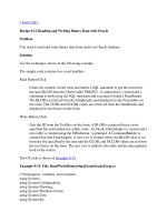
A Cisco router running ISIS can be an intermediate system (IS) or an end system
(ES). An IS node is simple a routing node in an OSI network. An ES node is gener-
ally an end-user device on a network. Figure 6.2 shows a typical ISIS environment.
As you can see in Figure 6.2, the communication between end systems and an
intermediate system is identified as an ES-IS connection. Communication be-
tween IS end systems is referred to as an ISIS connection. Figure 6.2 also defines
areas in the ISIS environment that reduce the routing table’s size and memory
requirements—namely, router R1 in area 1 and R2 in area 2. Routers that have
ES-IS and ISIS connections will maintain a different database for each connec-
tion. Further, routers in the same area will maintain a Level 1 (L1) database,
while routers in different areas will need to maintain Level 1 and Level 2 (L1/
L2) databases. These are the link-state database used by ISIS.
Configuration of ISIS
To enable ISIS on a Cisco router, you must perform the following configura-
tion tasks:
➤ Enable ISIS with the router isis command.
19
○○○○○○○○○○○○○○○○○○○○○○○○○○○○○○○○○○○○○○○○
Routing and Switching Algorithms
➤ Configure ISIS interface parameters.
➤ Configure area parameters.
➤ Configure any miscellaneous parameters.
The three methods (referred to as network entities) used to define an ISIS area
and their field formats are:
➤ Simple—Area System ID SEL
➤ OSI—Domain Area System ID SEL
➤ GOSIP—AFI ICD DFI AAI Reserved RDI Area System ID SEL
The meaning of each network entity field is defined as follows:
➤ AFI—Authority and format identifier (47, for Cisco routers)
➤ ICD—International code designator
➤ DFI—Domain-specific part
➤ AAI—Administrative authority identifier
➤ RDI—Routing domain identifier (an autonomous system number)
➤ SEL—Selector byte used to ensure uniqueness in the address (NSAP is Net-
work Service Access.)
Router
R1
Router
R2
PC
ES-IS
Token
Ring
PC
ES-IS
ISIS
Area 1
Area 1
Area 2
Area 2
Figure 6.2 ISIS terminolgy.
20
○○○○○○○○○○○○○○○○○○○○○○○○○○○○○○○○○○○○○○○○
Chapter 6
➤ Area—This value is used by level 2 routers
➤ System ID—Used by level 1 routers typically an interface MAC-address
Note: You are not be expected to remember these formats. They are included here for
your reference only.
Let’s configure the routers in Figure 6.2 for ISIS and place each router in the
same domain. We’ll use the simple address format and enable ISIS on all inter-
faces. The area ID on all four routers will be set to 47. Listings 6.13 through 6.16
display the ISIS configuration on routers R1, R2, R3, and R4.
Listing 6.13 ISIS configuration on R1.
hostname R1
clns routing
interface Ethernet0
ip address 10.1.1.1 255.255.255.0
ip router isis
!
interface Serial1
ip address 10.1.7.1 255.255.255.0
ip router isis
bandwidth 64
clockrate 64000
!
interface Serial2
ip address 10.1.2.1 255.255.255.0
ip router isis
interface Serial3
ip address 10.1.4.2 255.255.255.0
ip router isis
router isis
net 47.0000.0c8e.774b.00
Listing 6.14 ISIS configuration on R2.
Hostname R2
clns routing
!
interface Ethernet0
ip address 10.1.3.1 255.255.255.0
ip router isis
bridge-group 1
!
interface Serial0
ip address 10.1.5.1 255.255.255.0
ip router isis
21
○○○○○○○○○○○○○○○○○○○○○○○○○○○○○○○○○○○○○○○○
Routing and Switching Algorithms
bandwidth 64
no fair-queue
clockrate 64000
!
interface Serial1
ip address 10.1.8.2 255.255.255.0
ip router isis
bandwidth 64
clockrate 64000
bridge-group 1
!
interface Serial3
ip address 10.1.2.2 255.255.255.0
ip router isis
!
router isis
net 47.0000.0c75.cf24.00
Listing 6.15 ISIS configuration on R3.
Hostname R3
clns routing
interface Ethernet0
ip address 10.1.6.1 255.255.255.0
ip router isis
!
interface Serial0
ip address 10.1.7.2 255.255.255.0
ip router isis
!
interface Serial1
ip address 10.1.5.2 255.255.255.0
ip router isis
!
router isis
net 47.aa00.0400.0120.00
Listing 6.16 ISIS configuration on R4.
Hostname R4
clns routing
!
interface Ethernet0
ip address 10.1.9.1 255.255.255.0
ip router isis
!
interface Serial0
ip address 10.1.8.1 255.255.255.0
ip router isis
22
○○○○○○○○○○○○○○○○○○○○○○○○○○○○○○○○○○○○○○○○
Chapter 6
!
interface Serial1
ip address 10.1.7.1 255.255.255.0
bandwidth 64
!
interface Serial2
ip address 10.1.4.1 255.255.255.0
ip router isis
router isis
net 47.0000.0c75.d97e.00
As you can see in the preceding four listings, each router has a defined network
entry and the ISIS enabled interfaces that will listen and send ISIS updates.
Listing 6.17 displays the IP routing table from R1.
Listing 6.17 The sh ip route command after configuring ISIS on R1.
R1#sh ip route
10.0.0.0/24 is subnetted, 9 subnets
i L1 10.1.9.0 [115/20] via 10.1.4.1, Serial3
i L1 10.1.8.0 [115/20] via 10.1.4.1, Serial3
[115/20] via 10.1.2.2, Serial2
i L1 10.1.3.0 [115/20] via 10.1.2.2, Serial2
C 10.1.2.0 is directly connected, Serial2
C 10.1.1.0 is directly connected, Ethernet0
C 10.1.7.0 is directly connected, Serial1
i L1 10.1.6.0 [115/20] via 10.1.7.2, Serial1
i L1 10.1.5.0 [115/20] via 10.1.7.2, Serial1
[115/20] via 10.1.2.2, Serial2
C 10.1.4.0 is directly connected, Serial3
As you can see in Listing 6.17, the remote networks are reachable through ISIS.
The administrative distance for ISIS is 115, and the metric is 20. The left-hand
side of the displays shown with lower case letter i, which indicates ISIS is the
routing protocol used to reach the remote network. You can display the protocol
characteristics on any ISIS router by using the show ip protocols IOS command,
as shown in Listing 6.18.
Listing 6.18 The show ip protocols command after enabling ISIS.
Routing Protocol is "isis"
Sending updates every 0 seconds
Invalid after 0 seconds, hold down 0, flushed after 0
Outgoing update filter list for all interfaces is not set
Incoming update filter list for all interfaces is not set
Redistributing: isis
23
○○○○○○○○○○○○○○○○○○○○○○○○○○○○○○○○○○○○○○○○
Routing and Switching Algorithms
Address Summarization:
None
Routing for Networks:
Ethernet0
Serial1
Serial2
Serial3
Routing Information Sources:
Gateway Distance Last Update
10.1.2.2 115 00:05:16
10.1.7.2 115 00:05:17
10.1.4.1 115 00:05:17
Distance: (default is 115)
Notice in Listing 6.18 that updates are not sent unless a change occurs, like any
link-state protocol. To configure a default route, you use the default-information
originate command; otherwise, the default router will not be advertised. Listing
6.19 outlines the configuration on router R4 required to advertise a default route.
Listing 6.19 Default route configuration on router R4.
hostname R4
router isis
net 47.0000.0c75.d97e.00
default-information originate
ip route 0.0.0.0 0.0.0.0 null0
!Injects a Default route
The routing table for router R1, shown in Listing 6.20, shows that a default route
has been installed into the routing table.
Listing 6.20 The show ip route command showing a default route on router R1.
R1#sh ip route
.....
i L1 10.1.5.0 [115/20] via 10.1.7.2, Serial1
[115/20] via 10.1.2.2, Serial2
C 10.1.4.0 is directly connected, Serial3
i*L2 0.0.0.0/0 [115/10] via 10.1.4.1, Serial3
As you can see in Listing 6.20, the default router for R1 is via Serial 3 or router R4.
There are many configuration and display options for ISIS. Table 6.4 provides a
summary of the major commands available on a Cisco router when running ISIS.
Another very popular link-state protocol is Open Shortest Path First (OSPF).
24
○○○○○○○○○○○○○○○○○○○○○○○○○○○○○○○○○○○○○○○○
Chapter 6
Open Shortest Path First (OSPF)
Open Shortest Path First (OSPF) is a link-state protocol used by internal net-
works. This means that OSPF distributes information between routers belong-
ing to the same autonomous system. OSPF runs over IP enabled networks and
OSPF has been defined in many RFCs over the years.
OSPF was originally developed in RFC 1131, and its most recent specifications
are in RFC 2328. OSPF was designed to handle large IP networks and manage
them into smaller networks called areas. Areas are used to reduce memory and
CPU requirements. OSPF is much more process intensive than RIP, IGRP, and
EIGRP.
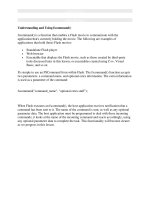
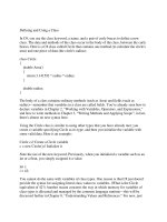
The popularity of OSPF ensures that it will remain as a primary routing protocol
for some years to come. Figure 6.3 illustrates a brief history of OSPF, beginning
with its inception in 1989.
The main features of OSPF include the following:
➤ Supports VLSM and classless behavior.
➤ Uses a metric based on a cost value. The formula used is 10
8
/Bandwidth in
BPS.
➤ Supports equal cost load balancing up to six paths.
➤ Uses hello packets to discover and maintain links to other routers, which
reduces bandwidth requirements.
➤ Supports authentication.
Table 6.4 Summary of ISIS commands.
Command Description
router isis Enables ISIS.
net entity Configures the network for the router.
ip router isis Enables ISIS on a local interface.
isis metric Sets the metric used by ISIS for Level 1 or 2 interfaces.
isis hello-interval Sets the hello interval in seconds.
isis password Sets the password used in authentication.
default-information originate Advertises a default route.
summary-address Summarizes networks.
show isis database Displays the ISIS link-state database.
show isis spf-log Displays the number of times the SPF algorithm has
been run due to network changes.
25
○○○○○○○○○○○○○○○○○○○○○○○○○○○○○○○○○○○○○○○○
Routing and Switching Algorithms
➤ Provides fast convergence.
➤ Provides network summarization.
➤ Supports dial-on-demand links.
Before you look at an example of enabling OSPF, you should review some of the
key concepts and terminology used in OSPF networks.
OSPF Key Concepts and Terminology
In this section, we will discuss concepts and terminology that are used in OSPF
network. Namely, this section addresses the following topics:
➤ Adjacency
➤ Router ID
➤ Shortest path first (SPF) Algorithm
➤ Area border routers (ABRs)
➤ Virtual links
➤ Authentication
➤ OSPF over demand circuits
➤ OSPF network types and broadcast media
➤ Designated and backup designated routers
OSPF,
version 1
RFC 1131
Interaction
with BGP
OSPF over
dial-up
support added
OSPF,
version 2
MIB added
OSPF,
version 2
updated in
RFC 1583
OSPF,
version 2
updated in
RFC 2178
(current)
OSPF
version 2
updated in
RFC 2328
1989
1991
1992
1994
1995
1997
1998
Figure 6.3 The evolution of OSPF.