Tài liệu In this lab, 2 ISDN routers are required. If ISDN routers are not available, review the lab to become familiar with the process. An Adtran Atlas550 ISDN emulator is used to simulate the switch/ISDN cloud. pdf
Bạn đang xem bản rút gọn của tài liệu. Xem và tải ngay bản đầy đủ của tài liệu tại đây (206.77 KB, 8 trang )
1 - 8 CCNA 4: WAN Technologies v 3.0 - Lab 4.3.7 Copyright 2003, Cisco Systems, Inc.
Lab 4.3.7 Configuring Dialer Profiles
Objective
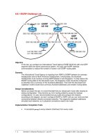
• Configure ISDN Dialer Profiles on the routers enabling a dial-on-demand routing (DDR) call to be
made from two remote routers simultaneously into a central ISDN BRI router.
Background/Preparation
In this lab, 3 ISDN routers are required. If ISDN routers are not available, review the lab to become
familiar with the process. An Adtran Atlas550 ISDN emulator is used to simulate the switch/ISDN
cloud.
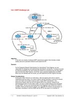
Cable a network similar to the one in the diagram above. Any router that meets the interface
requirements displayed on the above diagram may be used. This includes the following and any of
their possible combinations:
• 800 series routers
• 1600 series routers
• 1700 series routers
• 2500 series routers
• 2600 series routers
2 - 8 CCNA 4: WAN Technologies v 3.0 - Lab 4.3.7 Copyright 2003, Cisco Systems, Inc.
Please refer to the chart at the end of the lab to correctly identify the interface identifiers to be used
based on the equipment in the lab. The configuration output used in this lab is produced from 1721
series routers. Any other router used may produce slightly different output. Conduct the following
steps on each router unless specifically instructed otherwise.
Start a HyperTerminal session as.
Note: Refer to the erase and reload instructions at the end of this lab. Perform those steps on all
routers in this lab assignment before continuing.
Step 1 Configure the router
Configure the following according to the chart:
• The hostname
• The console
• The virtual terminal
• The enable passwords
If there is a problem completing this, refer to the Network Address Translation (NAT) configuration
lab.
Step 2 Define switch type and spid numbers
To configure the switch type and spid numbers use the following commands.
Router(config)#hostname Tokyo
Tokyo(config)#enable secret class
Tokyo(config)#isdn switch-type basic-ni
Tokyo(config)#interface fastethernet 0
Tokyo(config-if)#ip address 192.168.1.1 255.255.255.0
Tokyo(config-if)#no shutdown
Tokyo(config-if)#exit
Tokyo(config)#interface bri 0
Tokyo(config-if)#isdn spid1 51055510000001 5551000
Tokyo(config-if)#isdn spid2 51055510010001 5551001
Tokyo(config-if)#no shutdown
Router(config)#hostname Moscow
Moscow(config)#enable secret class
Moscow(config)#isdn switch-type basic-ni
Moscow(config)#interface fastethernet 0
Moscow(config-if)#ip address 192.168.2.1 255.255.255.0
Moscow(config-if)#no shutdown
Moscow(config-if)#exit
Moscow(config)#interface bri 0
Moscow(config-if)#isdn spid1 51055520000001 5552000
Moscow(config-if)#isdn spid2 51055520010001 5552001
Moscow(config-if)#no shutdown
Router(config)#hostname Sydney
Sydney(config)#enable secret class
Sydney(config)#isdn switch-type basic-ni
Sydney(config)#interface fastethernet 0
Sydney(config-if)#ip address 192.168.3.1 255.255.255.0
Sydney(config-if)#no shutdown
Sydney(config-if)#exit
Sydney(config)#interface bri 0
Sydney(config-if)#isdn spid1 51055530000001 5553000
Sydney(config-if)#isdn spid2 51055530010001 5553001
3 - 8 CCNA 4: WAN Technologies v 3.0 - Lab 4.3.7 Copyright 2003, Cisco Systems, Inc.
Sydney(config-if)#no shutdown
Step 3 Defining static routes for DDR
Use static and default routes instead of dynamic routing, in order to reduce the cost of the dialup
connection. To configure a static route, the network address of the network that is going to be
reached must be known. The IP address of the next router on the path to this destination must be
known as well.
Moscow#configure terminal
Moscow(config)#ip route 0.0.0.0 0.0.0.0 192.168.253.1
Sydney#configure terminal
Sydney(config)#ip route 0.0.0.0 0.0.0.0 192.168.254.1
Tokyo#configure terminal
Tokyo(config)#ip route 192.168.2.0 255.255.255.0 192.168.253.2
Tokyo(config)#ip route 192.168.3.0 255.255.255.0 192.168.254.2
Step 4 Specifying interesting traffic for DDR
Traffic must be defined as ‘interesting’ to cause the DDR interface to dialup the remote router. For
the moment, declare that all IP traffic is interesting using the dialer-list command.
Moscow(config)#dialer-list 1 protocol ip permit
Moscow(config)#interface dialer 0
Moscow(config-if)#dialer-group 1
Sydney(config)#dialer-list 1 protocol ip permit
Sydney(config)#interface dialer 0
Sydney(config-if)#dialer-group 1
Tokyo#configure terminal
Tokyo(config)#dialer-list 1 protocol ip permit
Tokyo(config)#interface dialer 1
Tokyo(config-if)#description The Profile for the Moscow router
Tokyo(config-if)#dialer-group 1
Tokyo(config-if)#interface dialer 2
Tokyo(config-if)#description The Profile for the Sydney router
Tokyo(config-if)#dialer-group 1
Step 5 Configuring DDR dialer information
Configure the correct dialer information so that the dialer profile and dialer interface function
correctly. This includes all of the following:
• IP address information
• PPP configuration
• Name
• Passwords
• Dial number
Tokyo(config)#interface dialer 1
Tokyo(config-if)#ip address 192.168.253.1 255.255.255.0
4 - 8 CCNA 4: WAN Technologies v 3.0 - Lab 4.3.7 Copyright 2003, Cisco Systems, Inc.
Tokyo(config-if)#interface dialer 2
Tokyo(config-if)#ip address 192.168.254.1 255.255.255.0
Tokyo(config-if)#interface bri 0
Tokyo(config-if)#encapsulation ppp
Tokyo(config-if)#ppp authentication chap
Tokyo(config-if)#interface dialer 1
Tokyo(config-if)#encapsulation ppp
Tokyo(config-if)#ppp authentication chap
Tokyo(config-if)#interface dialer 2
Tokyo(config-if)#encapsulation ppp
Tokyo(config-if)#ppp authentication chap
Tokyo(config-if)#exit
Tokyo(config)#username Moscow password class
Tokyo(config)#username Sydney password class
Moscow(config)#interface dialer 0
Moscow(config-if)#ip address 192.168.253.2 255.255.255.0
Moscow(config-if)#interface bri 0
Moscow(config-if)#encapsulation ppp
Moscow(config-if)#ppp authentication chap
Moscow(config-if)#interface dialer 0
Moscow(config-if)#encapsulation ppp
Moscow(config-if)#ppp authentication chap
Moscow(config-if)#no shutdown
Moscow(config-if)#exit
Moscow(config)#username Tokyo password class
Sydney(config)#interface dialer 0
Sydney(config-if)#ip address 192.168.254.2 255.255.255.0
Sydney(config-if)#interface bri 0
Sydney(config-if)#encapsulation ppp
Sydney(config-if)#ppp authentication chap
Sydney(config-if)#interface dialer 0
Sydney(config-if)#encapsulation ppp
Sydney(config-if)#ppp authentication chap
Sydney(config-if)#no shutdown
Sydney(config-if)#exit
Sydney(config)#username Tokyo password class
Step 6 Configure dialer information
a. Next, the dial information must be configured to specify the remote name of the remote router in
the Dialer Profile. The dial string, or phone number to use to contact this remote device must
also be specified. Use the following commands to do this:
Tokyo(config)#interface dialer 1
Tokyo(config-if)#dialer remote-name Moscow
Tokyo(config-if)#dialer string 5552000
Tokyo(config-if)#dialer string 5552001
Tokyo(config-if)#interface dialer 2
Tokyo(config-if)#dialer remote-name Sydney
Tokyo(config-if)#dialer string 5553000
Tokyo(config-if)#dialer string 5553001
b. To configure the dial information on Moscow, use the following:
Moscow(config-if)#interface dialer 0
5 - 8 CCNA 4: WAN Technologies v 3.0 - Lab 4.3.7 Copyright 2003, Cisco Systems, Inc.
Moscow(config-if)#dialer remote-name Tokyo
Moscow(config-if)#dialer string 5551000
Moscow(config-if)#dialer string 5551001
c. To configure the dial information on Sydney, use the following:
Sydney(config-if)#interface dialer 0
Sydney(config-if)#dialer remote-name Tokyo
Sydney(config-if)#dialer string 5551000
Sydney(config-if)#dialer string 5551001
Step 7 Associate dialer profiles
a. Finally, associate the Dialer Profiles with the Dialer Interfaces that will be used, when needed.
Create a Dialer Pool, and put the interfaces and the associated Dialer Profiles in a common pool.
The commands for doing this are as follows:
Tokyo(config-if)#interface bri 0
Tokyo(config-if)#dialer pool-member 1
Tokyo(config-if)#interface dialer 1
Tokyo(config-if)#dialer pool 1
Tokyo(config-if)#interface dialer 2
Tokyo(config-if)#dialer pool 1
b. On Moscow, the commands issued would be as follows:
Moscow(config-if)#interface bri 0
Moscow(config-if)#dialer pool-member 1
Moscow(config-if)#interface dialer 0
Moscow(config-if)#dialer pool 1
c. Use the same commands to configure the Sydney router.
Step 8 Configure dialer timeouts
a. Configure a dialer idle-timeout of 60 seconds for each of the dialer interfaces:
Tokyo(config)# interface dialer 1
Tokyo(config-if)#dialer idle-timeout 60
Tokyo(config-if)#interface dialer 2
Tokyo(config-if)#dialer idle-timeout 60
b. Repeat these commands on Moscow and Sydney.
Step 9 View the Tokyo router configuration
a. To view the configuration, use the show running-config command:
Tokyo#show running-config
b. How many username statements are there?
__________________________________________________________________________