BÁO CÁO QUAN TRẮC BIẾN DẠNG CÔNG TRÌNH 2
Bạn đang xem bản rút gọn của tài liệu. Xem và tải ngay bản đầy đủ của tài liệu tại đây (936.72 KB, 33 trang )
Noi Bai-Lao Cai Highway Project
Package A3: Km48+360 to Km80+000
Method statement for Soft soil treatment by PVD
POSA3-MS- PVD-A2-EN
1. GeneraL
- After studying the design documents drawing soft ground handling at Km48+420 ~
Km48+512.2, construction units were examined, survey the actual economic situation, social and
geographical shape, measuring water current, the geological situation at the construction site
2. Equipments and manpower.
- List of construction equipments:
No
1
2
3
4
5
6
7
8
9
Equipment
Bulldozer
Excavator
Vibration roller
Dump truck
Dump truck
Pump
Geodetic equipments
Sewing machine for geo-textile
fabric
Prefabricated
vertical
drains
machine
Type
110~140 HP
0.7~1.6 m3
16~ 36 ton
12~23 ton
8~10 ton
2~4 inches
Leveler, Total station
Quantity
2
2
2
5
5
2
2
2
Specialized
1
3. Materials
3.1. Borrow materials (Used for access road embankment and fine sand layer filling).
Borrow material is categorized as follows:
•
Borrow material for sub grade
•
Borrow material for road and counterweight embankment
•
Borrow material for fine sand layer(using black sand of Red River)
The Contractor shall use the suitable material from borrow pits for constructing
embankment, backfill, sub grade, shoulders, cohesive slope and other parts of the work as
shown on the Drawings, or as directed by the Engineer.
Borrow will be resorted to only
when shown on the Drawings or directed by the main Contractor, and then only from approved
sources.
In supplement to the above referred “Schedule of Materials” the Contractor shall submit
samples of materials corresponding to the lots for testing.
The Contractor shall permanently monitor the schedule for Quality control, testing and
acceptance, providing to the Consultants consistent reports as required in Specification
Dated: 20th Jun 2012: Version A2
-1-
Noi Bai-Lao Cai Highway Project
Package A3: Km48+360 to Km80+000
Method statement for Soft soil treatment by PVD
POSA3-MS- PVD-A2-EN
Section 01800 “Contractor's Quality Control”.
3.2. coarse SAND BLANKET (Using yellow sand of Lo River).
- Material must be submitted to Engineer for approval and tested in laboratory under
Engineer’s supervision before being used for embankment
- Testing frequency in construction progress is according to Article 2.4.1 “Coarse Sand
Blanket” in Section 03500 “Soft soil treatment measure” in General Technical Demands, details as
follows:
+ Testing and doing experiment to each material source needed to be approved.
+ Materials gathered on site: Every 500m3, all testing criteria shall be checked, except for
Compaction Test AASHTO T180 which is applied with frequency of 1000m3.
- Test result of sand must satisfy demands in Article 2.4.1(b) of Section 03500 “Soft soil
treatment measure” – General Technical Demands and following demands.
Technical demands
No
Norm name according to 22TCN 262-2000
1
Value
Sand for sand blanket
1.1
Organic content
<5.0%
1.2
Particles with a diameter >0.25mm
>50%
1.3
Particles with a diameter <0.08mm
<5.0%
1.4
Ratio D60/D10 or
(D30)2/D10*D60
>6.0
1< ÷ <3
1.5
Permeability K
≥ 10-4
3.3. Separation Geo-textile
Where required, as directed by the Engineer, the geo textile filter fabric for separating
the ”Coarse Sand Blanket” material from the existing soils shall conform to 22TCN248-98 for
high survivability fabric specifically used for highway separation applications.
The fabric shall be non-woven, needle punched, of continuous filament type and
manufactured from durable synthetic polymer. It shall have a permeability rate greater than
surrounding soils and have the minimum physical properties shown in Table 3.3.1
TABLE 3.3.1
Dated: 20th Jun 2012: Version A2
-2-
Noi Bai-Lao Cai Highway Project
Package A3: Km48+360 to Km80+000
Method statement for Soft soil treatment by PVD
POSA3-MS- PVD-A2-EN
Minimum Requirements for Separation-Geo textile Filter Fabric
Property
Required
Test Method
Values
2
Min. Weight g/m
130
ASTM D3776
Min. Strip Tensile Strength kN/m
12
ASTM D4595
Max. Elongation at Failure %
65
ASTM D4595
Min. CBR Puncture Strength N
1,500 - 5000
BS 6906-4
The filter fabric shall be procured from a reputable manufacturer and shall be
approved by the Engineer.
The Contractor shall present relevant certified test results and justify that the filter fabric
is suitable for the intended use.
The Apparent Opening Size (AOS) shall be in accordance with the requirements of Table
1 of AASHTO M288.
3.4. PREFABRICATEd VATICAL Drains (PVD)
- The physical and mechanical properties of the Prefabricated Vertical Drains (PVDs) to be
used in the Works shall be determined and confirmed by the Engineer based on the detailed
information provided by the Contractor regarding his proposed material. The information
shall consist of complete data from the supplier regarding the characteristics, test results
for Quality control, certificates, splicing methods and devices, construction statement for
proper
installation,
and
other relevant information that the Contractor might supply to
facilitate the evaluation and acceptance by the Main Contractor
- Paper filter will not be permitted. The use of paper filter will be considered as a serious
default to the Specifications by the Contractor.
- The test results on which was based the first Consultants approval shall be
routinely checked in the Quality control of the PVDs delivered to the site. One sample shall
be selected at random from every 10,000 m of PVD set for routine test at an approved laboratory
as directed by the Consultants (Clause 4.1.22TCN236-97). The routine tests shall include, but not
be limited to, the weight, width, thickness, apparent opening size of the filter, and other
physical
and
mechanical characteristics of the PVCs. Other tests shall be done at the direction
of the Engineer.
- T he Prefabricated Vertical Drains (PVDs) shall have two elements: a continuous plastic
Dated: 20th Jun 2012: Version A2
-3-
Noi Bai-Lao Cai Highway Project
Package A3: Km48+360 to Km80+000
Method statement for Soft soil treatment by PVD
POSA3-MS- PVD-A2-EN
drainage core wrapped by a non-woven geo textile filter jacket. These may be manufactured as
one unit or the filter may be wrapped about the core, overlapped and sealed to contain the core.
- The band drain shall be flexible, capable of being wound without damage on a drum
of a diameter approved by the Engineer, and strong enough so as not to break, tear, or lose its
drainage properties during installation.
- The selection of type/make of PVD shall be based on the following three main criteria:
① Possibility to ensure safe installation of the drain, which is also dependent on the
installation procedure;
② Long term performance of the drain with respect to the following properties:
+ The drain shall be sufficiently flexible to cope with the anticipated settlement of the soil
while maintaining continuity and without offering any significant support to the structure.
The drain material shall be inert and the drain properties shall be maintained throughout the
required period of consolidation.
+ The drain shall have the minimum resistance to the passage of water from the surrounding
soil without loss of fines from the soil, and without clogging the filter.
+ The drain shall be capable of transmitting water along its length without significant
resistance to flow and shall retain its required discharge capacity at the specified maximum
working depth.
③ Proven records of excellent function in full scale of the installations under similar
soil conditions.
- The
PVD
materials
shall
conform
to
the
requirements
established
by
Vietnamese standards 22TCN262-2000 as shown in Table 3.4.1.
- The drains shall be free of defects, rips, holes, or flaws.
TABLE 3.4.1: Minimum Requirements for PVD Material
Dated: 20th Jun 2012: Version A2
-4-
the
Noi Bai-Lao Cai Highway Project
Package A3: Km48+360 to Km80+000
Properties of PVD Jacket and Core
Apparent Opening Size, µ m
Grab Tensile Strength, kN
Drainage Capacity at 350kN/m2
pressure
Permeable Coefficient of filter cover
Stretching Strength correlatively with
less than 10% stretch for
discontinuation resistance installation
of PVD
Width of PVD
Method statement for Soft soil treatment by PVD
POSA3-MS- PVD-A2-EN
Test Designation
ASTM D4751 – 87
Requirements
Less than 75
ASTM D4632 – 91
ASTM D4716 – 87
Greater than 1.6
qw ≥ 60.10-6 m3/sec
ASTM D4491
ASTM 4595
≥ 1.10-4 m/sec
≥ 1kN/PVD
approx. 100mm ± 0.05mm
4. Construction measure.
Dated: 20th Jun 2012: Version A2
-5-
Noi Bai-Lao Cai Highway Project
Package A3: Km48+360 to Km80+000
Method statement for Soft soil treatment by PVD
POSA3-MS- PVD-A2-EN
REPAIR WORK
CARRY OUT ACCESS ROAD
- Receive Shop Drawing which have been approved by engineer
- Survey level of exit ground
- Submit the material supplyer and testing material
- Mobilization machine and manpower
- Survey the access Roadï
- Install Bamboo stake
- Carry out the first layer higher than usual water level 50 cm
- Carry out the next layer
- Cary out the pavement layer K95
SITE CLEARING & GRUBBING
UNSUITABLE MATERIAL
- Pumb out the water, wait for dry
- Site clearing and Grubbing
- Unsuitable material
- Acceptance work
BACKFILL BY BLACK SAND
- Transport black sand by Access Road
- Dump and grade
- Compact Black sand to 90%
- Acceptance work
NON-WOVEN GEO-TEXTILE
SAND FILL FOR SAND MAT K92
INSTALL PVD
INSTALL OBSERVATIONAL DEVICE
CARRY OUT GRADED FILTER
SAND BAGS
COMPENSATIVE SETTLEMENT
SURCHANGE AND REMOVE SURCHANGE
- Choise geo-textile, chart install
- Transport and install Geo-textile
- Acceptance work
- Transport material by Access Road
- Dump and grade
- Compact material until K92
- Acceptance work
- Fix and mark the install point
- Transport and prepare PVD
- Install PVD
- Carry out the remaining Sand fill for sand mat
- Acceptance Work
- Fix the location which install observational device
- Transport, check and install
- Observe during time
- Fix the location carry out Graded Filter and sand bags
- Carry out the Graded Filter
- Carry out the sand bags
- Carry out embankment K95 to design level
- Carry out the compensative settlement, surchange layer
- After design time, remove surchange layer
4.1 Preparation.
According to site situation, camp area is located as follows:
- Site Management Board
Dated: 20th Jun 2012: Version A2
-6-
Noi Bai-Lao Cai Highway Project
Package A3: Km48+360 to Km80+000
Method statement for Soft soil treatment by PVD
POSA3-MS- PVD-A2-EN
- Material gathering and pre cast concrete component production ground.
- Machine and equipment gathering ground
- Material store, toilet, cistern.
- House for workers
- Ground for daily meeting.
- Site security post.
Arrange stores and grounds reasonably in the construction site to garther materials easily and
conveniently.
Premises, pit, soil ground must be kept dry before construction by using drainage system.
Drainage system must be rapid while not causing soil erosion in construction progress.
After Employer hand-over landmark that defining location and standard landmark height,
Contractor brings to site. Landmarks must be located at stable, safe places and well-protected.
Landmarks are placed in premises control form.
Location of the work on the construction site is defined according to following orders:
+ First, define road heart of the work (drive in a stake at the heart of the work, interval:
20m/stake). These stakes are made from wood 40x40x700 mm, on the top of the stake there is a
nail positioning or concrete stakes shall be used.
+ Then take a standard measurement axis perpendicular to both sides to determine the shape.
Based on design drawings, reinforcement and ground situation to make landmarks of excavation
section.
+ Square grid coordinates to locate each lot according to design documents.
+ Excavation landmark points must be made by wooden stakes on which show: basic location,
basic of natural ground at stake location, slope from standard stake point.
+ Landmarks must be kept during construction progress, completion and hand-over.
+ Standard landmarks of the work are kept to supervise and evaluate deformation of the work
during its operation progress.
4.2
Access road construction.
Dated: 20th Jun 2012: Version A2
-7-
Noi Bai-Lao Cai Highway Project
Package A3: Km48+360 to Km80+000
Method statement for Soft soil treatment by PVD
POSA3-MS- PVD-A2-EN
- After defining centre line, it is expected during construction progress there is still water in site.
Contractor shall use gravel soil to prevent water and embank access road to transport unsutable
materials and sand for road embankment.
- Using car to transport soil and encroachment pour, use bulldozer on water surface 50 cm.
- Temporary culverts shall be installed along sand embankment area to release water. Culvert
position shown in shop drawings or as Engineer’s instructions.
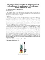
-In order to maintain stability of layer 50 cm during material transportation progress,
Typical cross section of service road as follows:
Using borrow material
K95 compaction
2500
2500
1
1:
500
Soft soil treatment area
1:2
6000
4.3
6000
Construction cofferdam.
- After determine center line, due to in Construction process still overflow water in working
area so constructor must be divide road for executing works and construct cofferdam by bag sand.
- The sand is put into sacks and transported by workers from the two ends up covering
encroachment.
- Using canvas to put in between cofferdam to make water proof layer.
- After reinforcing slope of road, contractor will remove sand bag and make up road according
shop drawing.
4.4
Excavation of unsuitable materials.
After dewatering 4-8 days until soft soil foundation is dry, Contractor shall do the excavation
of unsuitable materials.
Dated: 20th Jun 2012: Version A2
-8-
Noi Bai-Lao Cai Highway Project
Package A3: Km48+360 to Km80+000
Method statement for Soft soil treatment by PVD
POSA3-MS- PVD-A2-EN
Collect soil on cars by excavator to transport to disposal area.
For slope position close to access road, using excavator to make slope and bulldozer collect in
two sides for soft soil treatment.
Using bulldozer to make plane surface for check and take over.
Regularly check depth of excavation hole during embankment progress.
4.5
-
FINE SAND LAYER FILLING
Using cars to transport sand to site, bulldozers to make plane surface with satisfactory
thickness and height according to main Contractor’s instruction table on compaction coefficients.
* During rolling progress, check and water regularly to ensure limited humidity.
- After compaction, K90 sand layer <= 30cm. K90 embankment is done by self-operated bulldozer.
- To control height, every 10m at station stake place at centre line and 2 of road edges, Contractor
sets up stakes and use leveler to mark design height added with pressure coefficient on stake.
- After each K90 sand layer, Engineer shall check height of geometric dimension and density of
soil in-place. Density of soil in-place checked by the Rubber-Balloon Method. Doing compaction
on K90 surface is from two sides to the center (straight line), from low to high (slope line), from
belly to back (curved line). Do the next layer only when the previous layer reaches K9 0 density
and approved by Engineer. Ensure humidity of previous layer surface for its adhesiveness among
layers.
- After doing K90 compaction, if there is any place not satisfy height density according to layer
classification table, it must be changed or added material and construct again.
4.6
SEPARATION GEOTEXTILE FILTER FABRIC (12 kN/m)
- After Completion of black sand backfilling, filter fabric shall be supplied in rolls, marked to
show the length, width, type and weight of the material. Each roll shall be packed in a way to
protect the geo-textile from direct sunlight during transport and storage in accordance with the
supplier’s recommendation and as directed by the Engineer.
- Install geo-textile fabric manually at road border, after each embankment layer, install fabric
as required in design profile.
- Prior to laying the geo-textile all preceding works shall have been completed and the
ground surface shall be free of any sharp materials that may puncture or tear the fabric. The
ground surface shall be flat and even and any unevenness shall not exceed 100 mm and the
inclination shall be less than 5%.
Dated: 20th Jun 2012: Version A2
-9-
Noi Bai-Lao Cai Highway Project
Package A3: Km48+360 to Km80+000
Method statement for Soft soil treatment by PVD
POSA3-MS- PVD-A2-EN
- The layer of separation geo-textile shall be stretched out on properly leveled surfaces to
obtain a continuous filter layer, without kinks and creases. Overlap for joints shall be not less
than 0.50 m for transversal joints, and not less than 0.3 m for longitudinal joints. If
vertical soil drains are to be installed after the laying of the geo-textile, it may require the use
of stitched joints to minimize the disturbance to the geo-textile during the subsequent work on
the soil drains joint direction
- Borings and holes for pipes and rods of instruments shall be made as small as possible
and without damaging the filter fabric on the sides.
- Vehicles or construction equipment shall not be allowed on the filter fabric unless a
sufficiently thick layer of fill shall be placed carefully so as not to damage the fabric.
- Any damage to the filter fabric shall be repaired or replaced to the satisfaction of the
Engineer by the Contractor at his expense.
4.7 coarse sand BLANKET (50cm).
- Sand mat use to horizontal water drain, beside it make a plan for PVD machine moving.
- Sand use fill is Song Lo yellow sand.
- Transport sand by Dump truck on access road.
- Dump and grade by Bulldozer. Compact by Roller to compactness K92.
- Sand fill work will be done per layer to the design level, compactibility work by using suitable
machine, inspection by Engineer will be done for checking the compactness at site for per layer.
After all, acceptance work will be done.
- Compactibility testing at site will be done for per layer follow AASHTO T204 or AASHTO
T191, use 3 samples per 1500 cubic meter of back fill material or 500 cubic meter of back fill
material if quantity is less.
- Blanket shall observe demands on position and dimensions of typical horizontal surface and
details of shop drawings.
- Clays and dirty spot in construction must be cleaned to ensure construction quality.
- The drainage blanket shall conform to the location and dimensional requirements of the typical
cross-sections and details shown on the Drawings.
- Ensure that the clay materials rising from the PVD placement operations do not cause
Dated: 20th Jun 2012: Version A2
- 10 -
Noi Bai-Lao Cai Highway Project
Package A3: Km48+360 to Km80+000
Method statement for Soft soil treatment by PVD
POSA3-MS- PVD-A2-EN
contamination of the working surface. The Contractor shall remove the risen clay.
- Surface depressions around the installations shall be filled with the same material (as for CSB)
before commencing the works over the treated area.
- Acceptable tolerance of coarse sand blanket shall satisfy the following requirements.
Regulations on Tolerance of Coarse Sand Blanket
Allowable Limit
Test criteria
Density
Tolerance
Thickness
± 40mm
Height
± 25mm
Width
Not less than design
Measured at all crosssections
4.8 Install PREFABRICATEd VATICAL Drains (PVD)
4.9.1. Site preparation
Prior to PV drain installation, it is usually necessary to check elevation, clearing some remaining
obstacke & debris.
It may be important to minimize the disturbance of near-surface soils due to the operation of
construction equipment. If the surficial soils are excessively disturbed, the PV drains may be
displaced or damaged at the surface, resulting in inadequate connection with the drainage blanket.
Continuity between be drains and drainage blanket should be considered in the design of the
working mat and/or drainage blanket.
4.9.2. PVD installation
a. PVD installation Procedure
A number of sections shall be defined and each section will be indicated by a letter code. For each
section a predefined installation depth for the drains will be required. This depth can be calculated
from the maximum installation depth plus the thickness of the working platform.
The surveyor sets out a section based on the information from the main contractor. The four
corners of each section will be marked with pegs. The grids, which define the actual positions of
both the drains, have a square spacing of 1.3 m.
Dated: 20th Jun 2012: Version A2
- 11 -
Noi Bai-Lao Cai Highway Project
Package A3: Km48+360 to Km80+000
Method statement for Soft soil treatment by PVD
POSA3-MS- PVD-A2-EN
The individual drain position will be marked by pulling a nylon string, marked with the required
drain spacing along the alignment of the drain positions. A bamboo stick of approx. 400 mm
length and 4 mm thickness will mark the position of the drain or the anchor plate will be put in the
ground to indicate the position of the drain. The drain will be placed in position in the grid within
a tolerance of 150 mm.
The rig operator aligns the leader on top the drain location. The drain will be wrapped around the
fixture on the anchor plate (approximate dimensions: 170 x 85 x 1.2 mm), depending on soil
resistance an anchoring, the folded end of the wrapped drain will be pulled back into the mandrel,
until the plate rests against the base of the mandrel.
Dated: 20th Jun 2012: Version A2
- 12 -
Noi Bai-Lao Cai Highway Project
Package A3: Km48+360 to Km80+000
Method statement for Soft soil treatment by PVD
POSA3-MS- PVD-A2-EN
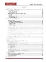
pl an o f ins t al l pvd /s ơ đồ t hi c « ng bÊc t hÊm
s t ep 1/ b í c 1
s t ep 2/ b í c 2
Dated: 20th Jun 2012: Version A2
- 13 -
Noi Bai-Lao Cai Highway Project
Package A3: Km48+360 to Km80+000
Method statement for Soft soil treatment by PVD
POSA3-MS- PVD-A2-EN
Các bước thi công
step 1: repair Equipment and material
bíc 1: chuÈn bb thiƠt bb vµ vËt liƯu
- Define start point on axis of installation PVD machine
Xác đđnh điểm bắt đầu trên trục của máy cắm bấc thấm.
- Calculate length of PVD
Tnh toán chiu dài c¾m cđa bÊc thÊm
- Always check the straightness of axis by lead
Kiểm tra độ thẳng của trục cắm bằng dây däi.
- Hold PVD's head with minimum length 30 cm by pin
Neo cố đđnh đầu bấc thấm với chiu dài nhỏ nhÊt 30cm b»ng ghim
step 2: install pvd/ bíc 2: c¾m bÊc thÊm
- PVD will be installed from a half of sand fill for sand mat layer to design level
BÊc thÊm sẽ đợc cắm t 1/2 chiu cao lớp cát thoát nớc đn chiu sâu TK.
- Error of location must be less than 150 mm
Sai sè vv̉ ṽ trƯ ph¶i nhá h¬n 150 mm
- Length of connection PVD must be more than 30 cm
Bấc thấm sẽ đợc nối với nhau với đoạn nối lớn hơn 30 cm
- Speed of install PVD will be from 0.15 - 0.6 m/s
Tốc độ thi công của máy t 0.15 - 0.6 m/sec
Designed level
cao độ tk
Dated: 20th Jun 2012: Version A2
- 14 -
Noi Bai-Lao Cai Highway Project
Package A3: Km48+360 to Km80+000
Method statement for Soft soil treatment by PVD
POSA3-MS- PVD-A2-EN
s t ep 3: pu l l pv d axis / b í c 3: kÐo t r ơ c c ¾m PVD
- PVD had to cut with the minimum remain
of 200 mm from top of sand fill for sand mat
- BÊc thÊm ph¶i đ ợ c cắ
t còn lạ i
tối thiểu 200 mm tính từ mặ
t cát.
t r ục
axis
pv d
Bấc t h ấm
Des ig n ed l ev el
c ao ®é TK
An c h o r
s t ep 4: s an d fi l l f o r s an d mat /
b ớ c 4: đắp ph ần c ò n l ¹ i c đ a l í p ®Ưm c ¸ t
- Carry out Sand fill for sand mat must be done carefully, do not demolish PVD
Thi công phần còn lạ i của lớ p đ
ệm cát phải cẩn thận đ
ể tránh làm hỏng bấc thấm
- Compaction will be done by Vibration Roller and waterring to k95 compaction
Đ ầm nén đ ợ c tiến hành vớ i lu rung và t ớ i n ớ c đ
ạ t tớ i ®
é chỈ
t k95
Th e r e main in g o f s an d fi l l f o r s an d mat h av e min imu m t h ic kn es s 20c m
ph Çn c ò n l ạ i c ủ a t ần g đệm c á t t ố i t hiểu 20c m
Des ig n ed l evel
c ao ®é TK
Dated: 20th Jun 2012: Version A2
- 15 -
Noi Bai-Lao Cai Highway Project
Package A3: Km48+360 to Km80+000
Method statement for Soft soil treatment by PVD
POSA3-MS- PVD-A2-EN
Installation machine orgnization
Dated: 20th Jun 2012: Version A2
- 16 -
Noi Bai-Lao Cai Highway Project
Package A3: Km48+360 to Km80+000
Method statement for Soft soil treatment by PVD
POSA3-MS- PVD-A2-EN
The hydraulic motors of the machine now push the mandrel to the design depth. The deep drains
will be installed to a depth given by the CLIENT. The operator will see on the display of the drain
logger, if the mandrel has been inserted till the required depth. This actual depth may vary due to
irregularities in the layer profile; this has to be taken into Hanaco Company account by both
CLIENT and CONTRACTOR. When the CONTRACTOR encounters problems with anchoring
the drain, due to too little resistance, the CONTRACTOR can alter the installation depth. In that
case, the CONTRACTOR will install the drains to a depth that is sufficient to anchor them. The
drain roll is mounted on the side of leader allowing the drain to be fed into the mandrel through a
series of rollers, which prevent damage and minimize friction.
On reaching the agreed depth of the drains, the operation is reversed and the mandrel is withdrawn
from the ground. The anchor plate locks itself at the driven depth such that the drain is fixed as the
mandrel is retracted. Once the mandrel clears the ground surfaces, the drain will be cut off
approximately 300 mm above the soil surface. The drain is now installed.
The rig operator will now align the leader onto the next drain position and the above procedure
will be repeated.
Anchor :
(14-16) cm
11 cm
(7-8)cm
Steel 1mm
Anchor
(14-16) cm
d= (0,5-0,7)mm
11 cm
Steel 1mm
Achor
Fig. 1: Top view and site view of the anchor plate.
Dated: 20th Jun 2012: Version A2
- 17 -
Noi Bai-Lao Cai Highway Project
Package A3: Km48+360 to Km80+000
Method statement for Soft soil treatment by PVD
POSA3-MS- PVD-A2-EN
b. Connection of PVD to Steel Anchor Plate.
A length of approximately 200 mm of PVD is pulled out from the mandrel, wrapped around the
fixture on the steel anchor plate and folded back tightly. Due to the stiffness of the PVD, the
folded part then secures itself to the steel anchor plate. As described aboved the drain is pulled
back into the mandrel until the plate rests against the mandrel.
PVD
20 cm
Anchor
c. PVD Joint and Lap Length
Joining the new to the old PVD shall be in accordance with the following procedure:
-
The last approx. 300 mm length of the old the old roll is guided into the
beginning of the new roll.
- The area of the overlap is then stapled together with sufficient stapes to secure the strength
of the joint and to avoid the two ends becoming separated while the mandrel drives the
PVD into the ground.
4.9
Settlement observation installation.
+ Pore water pressure and settlement at a depth in the soft soil layer: The monitoring data show the
vertical absorbability of water through PVD to sand layer. Determine the hydrostatic change in the
ground, therefore understand the consolidation of the ground under effect of embankment and
surcharge placement. Monitoring data of the pore water pressure at difference position in the soft
Dated: 20th Jun 2012: Version A2
- 18 -
Noi Bai-Lao Cai Highway Project
Package A3: Km48+360 to Km80+000
Method statement for Soft soil treatment by PVD
POSA3-MS- PVD-A2-EN
soil, in pair with monitoring of other parameter( settlement and lateral displacement) allow the
engineer to assess the stability of the embankment slope during the course of surcharging. Detailed
data gathered can be used to predict possible failure therefore time of placement of additional
surcharge or removal of surcharge can be determine.
+ Surface settlement plate: monitor data present the settlement of ground surface to placement of
embankment on the soft soil during the construction of surcharge and after finishing the
construction. Additionally, these data can be used to determine possible failure (due to sudden
change in settlement rate outside of permitted range) and calculate accurately the remaining
quantity of surcharge material required.
+ Deep settlement plate: be installed at depth inside the soft soil layer. Gathered data present the
settlement of the soft soil layer at difference depth and therefore can be used to verify the surface
settlement data which still have some limitation. Deep and surface settlement data are used
together to monitor the stability of the embankment and the ground during the construction period
as well as to assessing the consolidation process at respective depth and difference period.
+ From monitoring data of the underground water level surrounding the area of surcharge, change
in exceed pore water pressure in the ground during the surcharge process can be assessed. Used in
junction with pore water pressure data, change in hydrostatic line and consolidation rate of the soft
soil can be determined.
+ Monitoring of lateral displacement of the ground used to evaluate the sliding stability of the
embankment and surcharge mass. Therefore suitable change in volume of surcharge can be made
to mitigate possible failure.
PART I. WATER LEVER OBSERVATION WELL
A.
CONTENT AND QUANTITY OF WORK
As the proposal drawing No 05 – Typical cross-section of monitoring instrument arrangement, we
establish 01 observation well at cross section Km48+440 (detail in attach drawing). The observation
well is constructed after embankment and structure is shown in the Fig 1.
B.
METHOD AND EQUIPMENT
I.
Water level observation equipment
Observation well is constructed after embankment, so we use drilling machine to install. We use
XY -1 drilling machine from China to drilling the bore holes, this machine’s specification in table
below.
Dated: 20th Jun 2012: Version A2
- 19 -
Noi Bai-Lao Cai Highway Project
Package A3: Km48+360 to Km80+000
Method statement for Soft soil treatment by PVD
POSA3-MS- PVD-A2-EN
Tab 1. Drilling machine specification
Machine type
XY - 1A
Specification
Max depth drill (m)
Max diameter of hole (mm)
Power (round/minute)
Hydraulic raise power: (ton)
Hydraulic press power: (ton)
Weight (kg)
150
152
150 – 650 rpm
2.0
1.5
600 - 650
Monitoring equipment is water level indicator of Slope Indicator or Encardio. The equipments are
qualified and meet all the requirements of the project.
Tab 2. Equipment for water level observation.
Specifications
No
Hole type
Pipe depth
Pipe diameter
Tape
Casagrande
50m
50mm
Various
Accuracy
±1mm
II.
Installing equipment
According to requirement, after embankment done we install observation well to the designed
depth by drilling machine XY -1. Observation well is 1.0m depth from ground level. The protect
pipe is PVC 20mm diameter with top cover.
The observation well structure is showed in the Fig 1.
Dated: 20th Jun 2012: Version A2
- 20 -
Noi Bai-Lao Cai Highway Project
Package A3: Km48+360 to Km80+000
Fig 1.
III.
Method statement for Soft soil treatment by PVD
POSA3-MS- PVD-A2-EN
Observation well profile
Monitoring method
1. Monitoring and Reading out data
Monitoring process is conducted according to the manufacturer's monitoring process. Every
observation well is monitored three times to take the average value.
Data of water level is recorded by water level indicator. After monitoring, data is summarized in
excel sheet and plotted in chart following cycles and comparing measured data to accepted water
level limitation.
2. Frequency of monitoring
Frequency of monitoring is once a week during the preloading progress
PART II. ELECTRICAL PIEZOMETER
A.
CONTENT AND QUANTITY OF WORK
As the proposal drawing No 05 – Typical cross-section of monitoring instrument arrangement, we
establish 02 electrical piezometer observation well with 3m and 6m depth from ground level at
cross section Km48+440. The pore water pressure hole structure is shown in the Fig 3.
Dated: 20th Jun 2012: Version A2
- 21 -
Noi Bai-Lao Cai Highway Project
Package A3: Km48+360 to Km80+000
B.
Method statement for Soft soil treatment by PVD
POSA3-MS- PVD-A2-EN
METHOD AND EQUIPMENT
I.
Piezometer equipment
We also use XY-1 to drill to designed depth. Monitoring equipment is vibrating wire by Slope
Indicator or Encardio. The equipments are qualified and meet all the requirements of the project.
Fig 2. Electrical piezometer
II.
Installing equipment
1. Bore hole structure
Push–in piezometers are installed in each monitoring points. These push-in piezometers are simply
installed inside steel pipe 20mm diameter to designed depth. Total of Six (06) piezometers
monitoring points are installed in the project. The piezometer structure is shown in the Fig 3
below.
Dated: 20th Jun 2012: Version A2
- 22 -
Noi Bai-Lao Cai Highway Project
Package A3: Km48+360 to Km80+000
Method statement for Soft soil treatment by PVD
POSA3-MS- PVD-A2-EN
Fig 3. Electrical piezometer structure
2. Procedure of installation
The installation of piezometer is carried out as follows
- Drilling to the designed depth.
- Clean bored holes with water; test the function of the piezometer.
- Drop coarse sand to the bottom of drilled hole with 0.4m thickness.
- Lower the piezometer to a the designed depth and test functions of the sensors
Dated: 20th Jun 2012: Version A2
- 23 -
Noi Bai-Lao Cai Highway Project
Package A3: Km48+360 to Km80+000
Method statement for Soft soil treatment by PVD
POSA3-MS- PVD-A2-EN
- Drop into the drilled hole with coarse sand thickness of 0.6m.
- Releasing betonies to reach to the thickness from 1.0m.
- Fill drilled hole with betonies grout - cement with ratio 8:1.
- Measure for the original data.
- Calibration shall be carried out before setting the meters for each piezometer.
- Cover to protect the cables after the pressure is stable, which is shown by the
initial measurement.
III.
Monitoring method
1. Monitoring and reading out data
VW Data recorder is used to read signal from piezomter. Data is expressed by the parameter
consisting of Frequency (Hz). Pore water pressure is calculated from Frequency (Hz) by equation
below:
Pressure = (A x Hz2)+ (B x Hz) + C (kPa)
(1)
Where: A, B and C are Calibration Factors supplying by Manufacture and expressing in VW
piezometer calibration certificate of each piezometer.
From the pore water pressure, the degree of consolidation (DOC) of soil can be determined as the
following formula:
DOC = 1 −
CurrentPWP − VacuumLine
TotalPWP − VacuumLine
(2)
In which:
Vacuum Line – The pore water pressure caused by pressure (kPa)
Current PWP – The pore water pressure recorded by Piezometer (kPa)
Total PWP – The pore water pressure caused by surcharge and other load on soil during soil
improvement (kPa).
After having results of pore water pressure and vacuum pressure, parameters in equation (3) is
calculated and drawn in same charts as Fig 4 below.
Dated: 20th Jun 2012: Version A2
- 24 -
Noi Bai-Lao Cai Highway Project
Package A3: Km48+360 to Km80+000
Method statement for Soft soil treatment by PVD
POSA3-MS- PVD-A2-EN
Fig 4. Schematic illustration of analyzing DOC by pore water pressure
For each specific case of the unsatisfactory results, analyses shall be done and the most appropriate
back-up plan will be pointed out according to monitoring data of different items.
2. Frequency of monitoring
Frequency of monitoring is once a week during the preloading progress. Monitoring cycle may be
changed, which matches with the speed of actual consolidation.
PART III. SETTLEMENT MONITORING
A.
CONTENT AND QUANTITY OF WORK
As proposal drawing No 05 – Typical cross-section of monitoring instrument arrangement, we
established 03 surface settlement plates and 02 deep settlement plates (01 plate with 3m depth and 01
plate with 6m depth from ground level) at cross section Km48+440.
B.
I.
METHOD AND EQUIPMENT
Equipment
Settlement monitoring equipment is Level Leica NAK2.
The method of settlement monitoring is the high precise levelling with accuracy equal to the 2nd
grade of state, the benchmarks levelling with accuracy equal to the 1st grade of stade. Use level
machine NAK2 with automatic level . The staffs are made of invar, made in Germany.
Dated: 20th Jun 2012: Version A2
- 25 -