Tài liệu FREQUENCY / PHASE EFFECTS OF ANTENNAS pdf
Bạn đang xem bản rút gọn của tài liệu. Xem và tải ngay bản đầy đủ của tài liệu tại đây (189.02 KB, 4 trang )
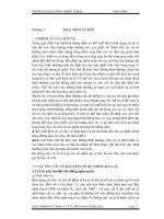
BW = 27.5E
L = 2.0 8
BW = 37.1E
L = 1.5 8
BW = 32.5E
L = 1.25 8
BW = 77.9E
L= 0.5 8
BW = 47.7E
L = 0.75 8
BW = 27.1E
L = 2.5 8
3-4.1
Figure 1. Frequency Effects
FREQUENCY / PHASE EFFECTS OF ANTENNAS
The radiation patterns of the antennas presented in the previous section are for antenna geometries most commonly
used. The antenna should be viewed as a matching network that takes the power from a transmission line (50 ohm, for
example), and matches it to the free space "impedance" of 377 ohms. The most critical parameter is the change of VSWR
with frequency. The pattern usually does not vary much from acceptable to the start of unacceptable VSWRs (> 2:1). For
a given physical antenna geometric size, the actual radiation pattern varies with frequency.
The antenna pattern depicted in Figure 1 is for the dipole pictured in Section 3-3. The maximum gain is normalized
to the outside of the polar plot and the major divisions correspond to 10 dB change. In this example, the dipole length (in
wavelengths) is varied, but the same result can be obtained by changing frequency with a fixed dipole length. From the
figure, it can be seen that side lobes start to form at 1.258 and the side lobe actually has more gain than the main beam at
1.58. Since the radiation pattern changes with frequency, the gain also changes.
Utilizing these techniques,
a phased array antenna
can be constructed by
simply electronically
varying the phase in a
progressive repetitive
manner in order to create a
specific scan pattern.
Progressive
Shift
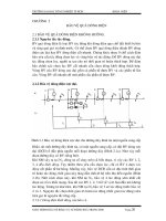
END FIRE ARRAY
= 0
= 90
= 180
= 0
= 90
TWO /2 DIPOLES
FOUR /2 DIPOLES
Spacing = / 2
Spacing = / 2
3-4.2
Figure 2. Phase / Array Effects
Figure 2 depicts phase/array effects, which are yet another method for obtaining varied radiation patterns. In the
figure, parallel dipoles are viewed from the end. It can be seen that varying the phase of the two transmissions can cause
the direction of the radiation pattern to change. This is the concept behind phased array antennas. Instead of having a
system mechanically sweeping the direction of the antenna through space, the phase of radiating components is varied
electronically, producing a moving pattern with no moving parts. It can also be seen that increasing the number of elements
further increases the directivity of the array. In an array, the pattern does vary considerably with frequency due to element
spacing (measured in wavelengths) and the frequency sensitivity of the phase shifting networks.
Two antennas that warrant special consideration are the phased array and the Rotman bootlace type lens. Both of
these antennas find wide application in EW, RADAR, and Communications. The phased array will be described first.
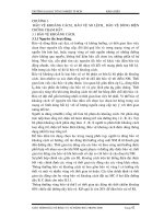
LINEAR PHASED ARRAY
The linear phased array with equal spaced elements is easiest to analyze and forms the basis for most array designs.
Figure 3 schematically illustrates a corporate feed linear array with element spacing d.
7
) N
6
) N
5
) N
4
) N
3
) N
2
) N
) N
0E
ANTENNA INPUT
2E
BROADSIDE
SCANNED BEAM
DIRECTION
RADIATORS
POWER
DISTRIBUTION
NETWORK
0E - 360E
PHASE
SHIFTERS
A
n
e
j N n
A
1
e
j N 1
A
0
e
j N o
d
EQUIPHASE
FRONT
)N= d sin 2
o
2B
8
Array Gain ' G
e
(2) @
j
N
n'1
A(n) e
jN(n)
e
jnkdsin2
3-4.3
Figure 3. Corporate Fed Phased Array
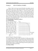
Figure 4. Beam Distortion
It is the simplest and is still
widely used. By controlling the phase
and amplitude of excitation to each
element, as depicted, we can control
the direction and shape of the beam
radiated by the array. The phase
excitation, N(n), controls the beam
pointing angle, 2 , in a phased array.
o
To produce a broadside beam, 2 =0,
o
requires phase excitation, N(n)=0.
Other scan angles require an
excitation, N(n) = nkd sin(2 ), for the
o
nth element where k is the wave
number (2B/8). In this manner a linear
phased array can radiate a beam in any
scan direction, 2 , provided the
o
element pattern has sufficient
beamwidth. The amplitude excitation, A , can be used to control beam shape and sidelobe levels. Often the amplitude
n
excitation is tapered in a manner similar to that used for aperture antennas to reduce the sidelobe levels. One of the
problems that can arise with a phased array is insufficient bandwidth, since the phase shift usually is not obtained through
the introduction of additional path length. However, it should be noted that at broadside the corporate feed does have equal
path length and would have good bandwidth for this scan angle.
The linear array described above would yield a narrow fan beam with
the narrow beamwidth in the plane of the array. To obtain a pencil beam it
would be necessary to array several of these line arrays. A problem associated
with all electronic scanning is beam distortion with scan angle. Figure 4
illustrates this phenomenon. It results in spread of the beam shape and a
consequent reduction in gain known as "scan loss". For an ideal array element,
scan loss is equal to the aperture size reduction (projected) in the scan
direction which varies as cos 2.
When elements are spaced greater than 8/2 apart, grating lobes are
possible when scanning. As the beam is scanned further from broadside, a
point is reached at which a second symmetrical main lobe is developed at the
negative scan angle from broadside. This condition is not wanted because
antenna gain is immediately reduced by 3 dB due to the second lobe. Grating
lobes are a significant problem in EW applications because the broad
frequency bandwidth requirements mean that at the high end of the frequency band, the elements may be spaced greater than
8/2.
There are many other factors to consider with a phased array such as coning, where the beam curves at large scan
angles, and mutual coupling between elements that affect match and excitation. They will not be covered in detail here.
Of interest is the gain of the array which is given by:
Where each element is as described in Section 3-4.
G (2) is the element gain which in this case has been taken the same for all elements. Note that if we set A(n)=1,
e
and N(n)=0, then at broadside where sin(2) = 0, the gain would be (N G ). This represents the maximum gain of the array,
e
which typically will not exceed nB, and is a familiar figure.
1
2
3
4
5
6
7
F
F
F
Beam 7
Wavefront
Beam 1
Wavefront
Beam 1
Beam 7
-20 -10 0 10 20 30 40
-40
-30
-20
-10
0
dB
Degrees
Primary Beam
Narrower
Higher Gain
Intermediate Beam
Wider
Lower Gain
3-4.4
Figure 5. Rotman Bootlace Lens
Figure 6. Primary and Intermediate Beam Formation in Lens Arrays
ROTMAN BOOTLACE LENS
Another method of feeding an array of
elements is to use a lens such as the Rotman
(rhymes with rotten) Bootlace type shown in
Figure 5. The lens consists of a parallel plate region
(nowadays microstrip or stripline construction) and
cables of specified length connecting the array of
elements to the parallel plate region. The geometry
of the lens and the cable lengths are designed so that
all ray paths traced from a beam port on the right
side to its associated wavefront on the left array port
side, are equal. This tailoring of the design is
accomplished at three focus points (beam ports 1, 4,
and 7 in Figure 5). Departure from perfect focus at
intermediate beam ports is negligible in most
designs.
The Rotman lens provides both true time delay phase shift and amplitude taper in one lens component. The true
time delay is one of the distinct advantages of the lens over the phase shifted array since that makes it independent of
frequency. To understand how the taper is obtained requires knowledge of the parallel plate region. For a stripline design
the unit would consist of a large flat plate-like center conductor sandwiched between two ground planes, and having a shape
much like that of the plan view outline shown in Figure 5 with individual tapered launchers (connectors) attached to each
beam port and array port. If the antenna is in the receive mode, the energy intercepted on the array port side can be
controlled by the angle subtended by the tapered sections of the connector (launcher) much like a larger antenna would
intercept a larger portion of energy from free space.
Unlike the phased array with its fine beam steering, the Rotman lens provides only a distinct set of beams. Fine
steering is obtained by combining beams either equally or unequally to form intermediate beams. As can be seen in
Figure 6, this results in a broader beam with less gain but lower side lobes than the primary beams.
High transmit power can be obtained using a Rotman lens by placing a low power amplifier between each lens
output port and its antenna. In this case a separate Rotman lens would have to be used for receiving.