Tài liệu PERFORMANCE TESTING OF OPTICAL FIBRE LINKS pptx
Bạn đang xem bản rút gọn của tài liệu. Xem và tải ngay bản đầy đủ của tài liệu tại đây (334.6 KB, 12 trang )
OF Testing ADC KRONE Requirements V7_1&3T Dr2Page 1 of 12
PERFORMANCE TESTING
OF OPTICAL FIBRE LINKS
FOR COMPLIANCE TO ISO/IEC 11801
Using the test methods set out in ISO/IEC 14763-3 - Testing of optical fibre cabling
Main changes from previous Version 6;
Item 8 3-Test Cord Method for Reference Setting is default method
Item 10 Field Calibration Cord, Launch & Tail Cords shall all have Reference Connectors
Item 11 Method of Removal of Field Calibration Cord Adaptors for Link Testing
Item 14 Insertion Loss for Reference and Non-Reference Connectors
Item 15 Example of Loss Budget Calculation Updated for Reference Connectors
Item 16 Links of 1/10GBE or any Channel to be Tested in 2 x Dir. at 2 x Wavelengths
Item 16 Links of Known Connectors for non-1/10GBE runs can be Tested in 1 x Dir.
Item 17 Qualification of Launch Cords
Item 17 Use adaptors at power meter to suit the Launch Cord & Tail Cord as necessary.
Item 18 Qualification of Tail & Field Calibration Cords
Item 19 The 3-Test Cord Reference Setting Method
Item 21 Reference Setting on LSPM Using the 1-Test Cord Method
Item 22 Qualification of Tail Cord for 1-Test Cord Method
Item 23 The 1-Test Cord Reference Setting Method for Non-1/10GBE Installations
Item 24 Effects of Different Zeroing Methods on Loss Budget
Appendix A Set Up for Fluke DSP Series with Fibre Test Head as an LSPM Tester
Appendix B TIA 568-C.3 draft requirements added for American projects
3-Test Cord Method
Reference Setting
Is Default Method
The 3-Test Cord Method produces more accurate test results with better consistency.
Version 7_1&3T Draft 2
ADC KRONE (Asia Pacific)
OF Testing ADC KRONE Requirements V7_1&3T Dr2Page 2 of 12
OPTICAL FIBRE TESTING FOR COMPLIANCE TO ISO/IEC 11801
1 All Optical Fibres, including Per-Terminated Optical Fibres shall be CLEANED after
installation and tested as a LINK for:
0 Visual inspection of all ends Recommended
1 Continuity and Maintenance of Polarity Required
2 Length Required
3 Propagation Delay Required
4 Optical Attenuation of Link: 2 x wavelengths Required (See Item 16)
[LINK testing includes the 2 x end connectors. CHANNEL testing does not include the 2 x end connectors.]
2 Visual inspection is not mandatory but if done, use a minimum x100 magnification for MMF,
x200 for SMF, both conducted to protect the viewer’s eyes. The core is a ”PASS” if it is
round, clear & featureless. The inner 1/2 of cladding is a ”PASS” if it is free of chips & cracks
but it may have some polishing marks. The outer 1/2 of cladding may contain some polishing
marks and chips but any chips must be less than 25% of the cladding circumference.
3 Continuity and Maintenance of Polarity of each optical fibre termination is checked
ensuring that “A” at the Near-End is “B” at the Far-End, and visa-versa. This can be done by;
1. visible light (eg a red light source) and inspecting opposite ends at the same time, or
2. using an LSPM that has been connected to the fibre at the far end, or
3. using an OTDR with a ‘tail cord’ connected to the correct fibre at the far end.
4 Length is verified by recording the cable length markings at each end and subtracting one
from the other, or by reading the length off a tester.
5 Propagation Delay PD is a calculation based on; PD = 5.0 nano-seconds/metre.
PD (in nS) = 5 x length (m).
Some testers are capable of measuring and recording PD; otherwise it must be calculated
and written on the Test Result Sheet for each fibre cable.
6 Optical Attenuation (Power Loss or Insertion Loss) tests must be done at both wavelengths
and in both directions for 1/10GBE applications (See Item 16). This will check for any
connector or splice defects, any cracked connectors, any accidental splicing or connecting of
50 μm and 62.5 μm fibres.
7 Power Loss (or Insertion Loss or Optical Attenuation) tests can be done using either,
Light Source & Power Meter (LSPM), or
Optical Time Domain Reflectometer (OTDR) See Item 16.
If conflict exists, correct testing using LSPM shall be taken as correct.
Where LSPM results exceed the Power Loss Budget, the link should be investigated with an
OTDR to determine the faulty component.
8 Reference Setting (Zeroing) Methods for LSPM Testers on MMF and SMF
Are the connectors on the LSPM tester the same as the connectors on the Link to be tested?
Is the test set-up for Simplex only testing?
NO – Use the 3-Test Cord Method of Reference Setting
(Eg. SC on Tester and LC on Link)
YES – Use either 3-Test Cord Method or 1-Test Cord Method of Reference Setting
(Eg. SC on tester and SC on both ends of Link)
OF Testing ADC KRONE Requirements V7_1&3T Dr2Page 3 of 12
9 Use of Mandrels or Coils (for both 3 & 1-Test Cord Methods)
For MMF, the LSPM Tester must have the correct Coupling Power Ratio for the cable under
test. Alternatively, this can be achieved by using a Mandrel Wrap on the Launch Cord for
mode stripping during Reference Setting and Testing.
For a 3 mm Launch Cord, 5 turns on 17 mm Ø for 62.5 µm (OM1)
5 turns on 22 mm Ø for 50 µm (OM2 and OM3)
For SMF, the LSPM launch cord shall have at least 2 x turns of 40±5 mm diameter, air-coiled
or on a mandrel, for stripping light out of the cladding and more consistent readings.
10 Test Cords and Field Calibration Cords (for both 3 & 1-Test Cord Methods)
All Test Cords & Field Calibration cords shall be Qualified. (See Item 17 for procedure)
Launch and Tail Cords for MMF & SMF LSPM testing shall be 1m to 5m each and shall
have a Reference Connector at one end.
Field Calibration Cord shall not exceed 2m in length and shall have Reference Connectors
at both ends.
Reference Connectors shall be the same type of connectors as the cabling to be tested.
Mated Reference Connectors shall have an attenuation of
≤ 0.10 dB for MMF, and ≤ 0.20 dB for SMF.
11 Field Calibration Cord and Adaptor Removal (for 3-Test Cord Method)
For both MMF and SMF cabling, after the 3-Test Cord Reference Setting has been done, the
central Field Calibration Cord shall be removed and the cabling under test connected.
For a Link, the 2 x adaptors are removed with the field calibration cord.
[For a Channel, the 2 x adaptors remain on the launch and tail cords.]
12 Acceptance criteria is;
1. Continuity & Polarity shall be correct, and
2. Length shall be recorded, and
3. Propogation Delay shall be recorded, and
4. Optical Attenuation (Power Loss) test result shall be less than the Power Loss Budget at
both the nominated wavelengths in both directions for 1/10GBE installations. (Item 16)
13 Power Loss Budget (PLB) in dB is the sum of the maximum component insertion loss
allowed under ISO/IEC 11801 Table 4, AS/NZS 3080, Cl 9.4 Table 26, and Cl 10.3 Table 46.
These requirements are set out in Item 14.
14 Component Power Loss
Component and
Wavelength
ISO/IEC 11801
Insertion Loss Maximum
Mated Ref to Non-Ref
Connector
at 850 & 1300 nm
at 1310 & 1550 nm
See Note 1
MMF 0.30 dB
SMF 0.50 dB
Splice
at 850 & 1300 nm
and at 1310 & 1550 nm
0.30 dB
MMF
at 850 nm
at 1300 nm
3.50 dB/km
1.50 dB/km
SMF
at 1310 & 1550 nm
1.00 dB/km
Note 1 Insertion Loss
Mated Reference to Reference Connector is 0.10 dB MMF and 0.20 dB SMF
Mated Reference to Non-Reference Connector is 0.30 dB MMF and 0.50 dB SMF
Mated Non-Reference to Non-Reference Connector is 0.75 dB MMF and SMF
{ Ref ISO/IEC 14763-3 Tables 3 & 4}
1 x Mated Connection
i.e. one
Ref/Non-Ref Connection
1/2
1/2
Reference Connector
Connector on installed cabling
Connector device (general)
198m
FD
ER
1
1
1m Splice
OF Testing ADC KRONE Requirements V7_1&3T Dr2Page 4 of 12
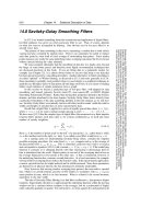
15 Example A fibre link consists of 198m OM3,
50/125 µm cable. In addition, there is a 1m
pigtail splice inside the FOBOT at each end.
What is the Power Loss Budget?
1m Splice
Item 15 Example
PLB
850
= 2 x Ref/Non-Ref Connectors matings + 2 x splices + 0.2 km x MMF
At Launch Cord & Tail Cord
PLB
850
= 2 x 0.30 + 2 x 0.30 + 0.2 x 3.50
PLB
850
= 1.90 dB maximum @ 850 nm
PLB
1300
= 2 x Ref/Non-Ref Connector matings + 2 x splice + 0.2km x MMF
PLB
1300
= 2 x 0.30 + 2 x 0.30 + 0.2 x 1.50
PLB
1300
= 1.50 dB maximum @ 1300 nm
Therefore, the tester readings must be
less than the maximum Power Loss Budget of;
16 Test Wavelength and Direction
Horizontal & Backbone Cabling, Within The Same Building
Where the MMF and SMF Link is to be used
for 1/10GBE or is a channel or has unknown
connectors, the test shall be done at:
Both wavelengths, in 2 x direction using LSPM Launch & Tail Cords.
The single reported Test Result at each wavelength shall be the single highest reading from
either direction, recorded to at least 2 decimal places.
{ Ref ISO/IEC 14763-3 Cl 9.1.1.3}
(Not the lowest reading, and not an average reading of both directions for LSPM testing)
Some installers choose to use only OTDR testing and not do LSPM testing. If this is done,
ADC KRONE will only accept the results if the average highest OTDR reading from
both
directions is calculated and written into an electronic record of results along with the PLB.
For MMF and SMF Links that have
known connectors and are not for 1/10GBE, test at;
Both wavelengths, in just 1 x direction using LSPM Launch & Tail Cords.
Inter-building Campus Cabling
Use LSPM 2 x wavelengths, both in 2 x directions,
AND ALSO
Use OTDR For Links less than 300m, It is not an ADC KRONE requirement.
For Links over 300m long, It is an ADC KRONE requirement.
2 x wavelengths, both in 2 x directions, using OTDR launch and tail cords
For OTDR tests, the single reported Test Result at each wavelength shall be the
average of
the highest readings from both directions. {
Ref ISO/IEC 14763-3 Cl 9.1.2.4}
[Because the scattering coefficients are usually different between launch cord, cable under test, and tail cord, the test
results will be different when tested in different directions. Therefore the readings are to be averaged.]
Some installers choose to use only OTDR testing and not do LSPM testing. If this is done,
ADC KRONE will only accept the results if the average highest reading from both directions is
calculated and written into an electronic record of results along with the PLB.
Launch & Tail Cord Lengths
PLB
850
= 1.90 dB There must always be a power loss. If
there is a power
gain, testers need a
new Reference Setting. See Item 19.
PLB
1300
= 1.50 dB
LSPM launch & tail cords are each → 1 – 5 m
OTDR launch & tail cords are typically Launch cord 100 m min
Tail cord 50 m min
OF Testing ADC KRONE Requirements V7_1&3T Dr2Page 5 of 12
17 Qualification of Launch Cord (Step 1)
Launch & Tail Cords shall have Reference Connectors one end, tester connectors other end.
Field Calibration Cords shall have Reference Connectors on both ends. (See Item 10)
For MMF, apply a Mandrel Wrap in the Launch Cord L1, 5 turns on 17 mm Ø for 62.5 µm
5 turns on 22 mm Ø for 50 µm
For SMF, apply coils in the Launch Cord L1 at least 2 x turns of 40±5mm
diameter air-coiled or on a mandrel.
Clean both the test cord connector ends. Connect L1 at the light source. Use an adaptor to
suit the cord at the power meter and connect. The adaptor is not included in the test results.
Place the test cord in such a way as to minimise movement during testing.
Turn on the light source and power meter and let them stabilise for several minutes.
Most meters allow you to set this reading to “0.00 dB”. The LSPM is now referenced to “Zero”.
.
18 Qualification of Tail Cord or Field Calibration Cord (Step 2)
Disconnect L1 from the Power Meter. Clean the test cord connector ends and apply a
Reference Adaptor (eg SMF adaptor) at the centre connection. Insert Tail Cord T1.
This second cord is acceptable if the power loss is less than 0.10 dB for MMF and 0.20 dB for
SMF
{Ref ISO/IEC 14763-3 Cl D.2
.}
If the reading is greater than 0.10 dB or 0.20 dB for MMF or SMF, repeat Step 2 after cleaning
the connectors, or use another test cord.
Repeat the Step 2 qualification process on as many test cords as is necessary to undertake
the LSPM testing. If duplex testing is done with the 3-Test Cord Method, the required cords
are;
2 x Launch Cords L1 each the same length between 1m – 5m long
2 x Tail Cords T1 each the same length as L1 between 1m – 5m long
2 x Field Calibration Cords each the same length less than 2m long
This Qualification of all test cords should be repeated periodically during the test program.
The Launch Cord L1, Tail Cord T1, Field Calibration Cord C1, and any other cords so tested
are now Qualified as acceptable for use in immediate LSPM testing.
The next step is to do the Reference Setting on the LSPM using the 3-Test Cord Method.
DO NOT disconnect L1
from the light source.
If disconnection
occurs, repeat Step 1.
Loss ≤ 0.10 dB for MMF
≤ 0.20 dB for SMF
DO NOT turn off the light
source or power meter
between measurements.
Light
Source
Power
Meter
L1
Use an adaptor
to suit the cord
T1
L1
Light
Source
Power
Meter
Reference
Connector
Use an
adaptor
to suit
the cord
Reference
Connector