Tài liệu động cơ G6EAGSL 2.7 Santa Fe. động cơ đốt trong
Bạn đang xem bản rút gọn của tài liệu. Xem và tải ngay bản đầy đủ của tài liệu tại đây (7.74 MB, 101 trang )
Engine (G6EA GSL 2.7)
GENERAL
INTAKE AND EXHAUST SYSTEM
ENGINE BLOCK
CYLINDER HEAD ASSEMBLY
COOLING SYSTEM
TIMING SYSTEM
LUBRICATION SYSTEM
ENGINE AND TRANSAXLE ASSEMBLY
EMA -2
ENGINE (G6EA - GSL 2.7)
GENERAL
SPECIFICATIONS
EAFA9CDF
Description
Specifications
Limit
General
Type
V-type, DOHC
Number of cylinder
6
Bore
86.7mm(3.4134in.)
Stroke
75mm(2.9528in.)
Total displacement
2,656cc
Compression ratio
10.4
Firing order
2-3-4-5-6-1
Valve timing
Intake valve
Exhaust valve
Opens (ATDC)
4 ~ -56
Closes (ABDC)
60 ~ 0
Opens (BBDC)
46
Closes (ATDC)
10
Cylinder head
Flatness of gasket surface
0.03mm(0.0012in.) or less
Flatness of manifold
mounting
Intake
0.15mm(0.0059in.) or less
Exhaust
0.15mm(0.0059in.) or less
Camshaft
Cam height
Journal outer
diameter
Bearing oil
clearance
LH
Camshaft
Intake
44.5mm(1.7520in.)
Exhaust
44.5mm(1.7520in.)
RH
Camshaft
Intake
44.5mm(1.7520in.)
Exhaust
44.5mm(1.7520in.)
LH
Camshaft
Intake
27.964 ~ 27.980mm(1.1009 ~ 1.1016in.)
Exhaust
27.964 ~ 27.980mm(1.1009 ~ 1.1016in.)
RH
Camshaft
Intake
27.964 ~ 27.980mm(1.1009 ~ 1.1016in.)
Exhaust
27.964 ~ 27.980mm(1.1009 ~ 1.1016in.)
Intake
0.020 ~ 0.057mm(0.0008 ~ 0.0022in.)
Exhaust
0.020 ~ 0.057mm(0.0008 ~ 0.0022in.)
End play
0.05 ~ 0.15mm(0.0020 ~ 0.0059in.)
Valve
Valve length
Stem outer diameter
Face angle
Intake
110.1mm(4.3346in.)
Exhaust
111.1mm(4.3740in.)
Intake
5.965 ~ 5.980mm(0.2348 ~ 0.2354in.)
Exhaust
5.950 ~ 5.965mm(0.2343 ~ 0.2348in.)
45 ~ 45.5
0.05mm(0.0020in.)
GENERAL
EMA -3
Description
Thickness of
valvehead(margin)
Valve stem to valve
guide clearance
Specifications
Limit
Intake
1.0mm(0.0394in.)
Exhaust
1.3mm(0.0512in.)
Intake
0.020 ~ 0.050mm(0.0008 ~ 0.0020in.)
0.10mm(0.0039in.)
or less
Exhaust
0.035 ~ 0.065mm(0.0014 ~ 0.0026in.)
0.13mm(0.0051in.)
or less
Intake
6.000 ~ 6.015mm(2.2362 ~ 2.2368in.)
Exhaust
6.000 ~ 6.015mm(2.2362 ~ 2.2368in.)
Intake
45.8 ~ 46.2mm(1.8031 ~ 1.8189in.)
Exhaust
46.8 ~ 47.2mm(1.8425 ~ 1.8583in.)
Valve guide
Inner diameter
Length
Valve spring
Free length
Load
46.8mm(1.8425in.)
Height: 35mm
180.5 ~ 199.5N(18.4 ~ 20.3Kgf,
40.6 ~ 44.8lb)
Height: 26.5mm
342 ~ 378N(34.9 ~ 38.6Kgf, 76.9 ~ 85.1lb)
Out of squareness
1.5 or less
MLA(Mechanical Lash Adjuster)
MLA outer diameter
Intake
29.964 ~ 29.980mm(1.1797 ~ 1.1803in.)
Exhaust
29.964 ~ 29.980mm(1.1797 ~ 1.1803in.)
Cylinder head tappet
bore inner diameter
Intake
30.000 ~ 30.025mm(1.1811 ~ 1.1821in.)
Exhaust
30.000 ~ 30.025mm(1.1811 ~ 1.1821in.)
MLA to tappet bore
clearance
Intake
Exhaust
0.020 ~ 0.061mm(0.0008 ~ 0.0024in.)
0.07mm(0.0027in.)
or less
0.020 ~ 0.061mm(0.0008 ~ 0.0024in.)
0.07mm(0.0027in.)
or less
0.17 ~ 0.23mm (0.0067 ~ 0.0090in.)
0.10 ~ 0.30mm
(0.0039 ~
0.0118in.)
0.27 ~ 0.33mm (0.0106 ~ 0.0129in.)
0.20 ~ 0.40mm
(0.0078 ~
0.0157in.)
Valve clearance
Intake
Exhaust
Cylinder block
Cylinder bore
96.00 ~ 96.03mm (3.7795 ~ 3.7807in.)
Flatness of gasket surface
Less than 0.05mm (0.0019in.)
[Less than 0.02mm (0.0008in.) / 150x150]
Piston
Piston outer diameter
95.96 ~ 95.99mm(3.7779 ~ 3.7791in.)
Piston to cylinder clearance
0.03 ~ 0.05mm(0.0012 ~ 0.0020in.)
EMA -4
ENGINE (G6EA - GSL 2.7)
Description
Ring groove width
Specifications
No. 1 ring groove
1.22 ~ 1.24mm (0.0480 ~ 0.0488in.)
No. 2 ring groove
1.22 ~ 1.24mm (0.0480 ~ 0.0488in.)
Oil ring groove
2.01 ~ 2.03mm (0.0791 ~ 0.0799in.)
Piston O.S.
Limit
0.25mm(0.0098in.)
Piston ring
Side clearance
End gap
No. 1 ring
0.04 ~ 0.08mm(0.0016 ~ 0.0031in.)
0.1mm(0.0039in.)
No. 2 ring
0.03 ~ 0.07mm(0.0012 ~ 0.0027in.)
0.1mm(0.0039in.)
Oil ring
0.06 ~ 0.15mm(0.0024 ~ 0.0059in.)
0.2mm(0.0079in.)
No. 1 ring
0.15 ~ 0.30mm(0.0059 ~ 0.0118in.)
0.6mm(0.0236in.)
No. 2 ring
0.30 ~ 0.45mm(0.0118 ~ 0.0177in.)
0.7mm(0.0275in.)
Oil ring
0.20 ~ 0.70mm(0.0078 ~ 0.0275in.)
0.8mm(0.0315in.)
Piston ring O.S.
0.25mm(0.0098in.)
Piston pin
Piston pin outer diameter
21.001 ~ 21.007mm(0.8268 ~ 0.8270in.)
Piston pin hole inner diameter
21.014 ~ 21.023mm(0.8273 ~ 0.8277in.)
Piston pin hole clearance
0.007 ~ 0.022mm(0.0003 ~ 0.0009in.)
Connecting rod small end inner diameter
20.974 ~ 20.985mm(0.8257 ~ 0.8262in.)
Connecting rod small end hole clearance
0.016 ~ 0.033mm(0.0006 ~ 0.0013in.)
Connecting rod
Connecting rod big end inner diameter
51.000 ~ 51.018mm(2.0079 ~ 2.0086in.)
Connecting rod bearing oil clearance
0.018 ~ 0.036mm(0.0007 ~ 0.0014in.)
Side clearance
0.1 ~ 0.25mm (0.0039 ~ 0.0098in.)
0.4mm(0.0157in.)
Crankshaft
Main journal outer diameter
61.982 ~ 62.000mm(2.4402 ~ 2.4409in.)
Pin journal outer diameter
47.982 ~ 48.000mm(1.8891 ~ 1.8898in.)
Main bearing oil clearance
0.004 ~ 0.022mm(0.0002 ~ 0.0009in.)
End play
0.07 ~ 0.25mm(0.0028 ~ 0.0098in.)
Oil pump
Relief valve opening pressure
490.33 ~ 588.40kPa(5.0 ~ 6.0kgf/cm²,
71.12 ~ 85.34 psi)
Engine oil
Oil quantity (Total)
4.5L(4.76U.S.qts,3.96lmp.qts)
Oil quantity (Oil pan)
4.2L(4.44U.S.qts,3.70lmp.qts)
Oil quantity (Oil filter)
0.3L(0.32U.S.qts,0.26lmp.qts)
Oil quality
Above SJ or SL
Oil pressure
130kPa(1.32kgf/cm²,18.77psi) [at
1000rpm,110 C(230 F)]
Cooling system
Cooling method
Forced circulation with electrical fan
0.30mm(0.0118in.)
GENERAL
EMA -5
Description
Coolant quantity
Thermostat
Radiator cap
Specifications
8.2~8.3L(8.66~8.77U.S.qts,7.22~7.30lmp.qts)
Type
Wax pellet type
Opening temperature
82±2 C (179.6±35.6 F)
Fully opened temperature
95 C (203 F)
Full lift
10mm (0.3937in.) or more
Main valve opening
pressure
93.16 ~ 122.58kpa(0.95 ~ 1.25 kg/cm²,
13.51 ~ 17.78psi)
Vacuum valve opening
pressure
0.98 ~ 4.90 kpa(0.01 ~ 0.05 kg/cm²,
0.14 ~ 0.71 psi)
Engine coolant temperature sensor
Type
Resistance
Thermister type
20 C (68 F)
2.31 ~ 2.59 k
80 C(176 F)
0.3222 k
Limit
EMA -6
ENGINE (G6EA - GSL 2.7)
TIGHTENING TORQUE
Quantity
Nm
kgf.m
lb-ft
Oil seal case bolt
3
9.8 ~ 11.8
1.0 ~ 1.2
7.2 ~ 8.7
Main bearing cap bolt(M10)
8
29.4 + 90
3.0 + 90
21.7 + 90
Main bearing cap bolt(M8)
8
15.7 + 90
1.6 + 90
11.6 ~ + 90
Rear plate bolt
1
9.8 ~ 11.8
1.0 ~ 1.2
7.2 ~ 8.7
Oil pump case bolt(8×25)
1
18.6 ~ 23.5
1.9 ~ 2.4
13.7 ~ 17.4
Oil pump case bolt(8×35)
1
18.6 ~ 23.5
1.9 ~ 2.4
13.7 ~ 17.4
TimingOil pump case bolt(8×65)
1
18.6 ~ 23.5
1.9 ~ 2.4
13.7 ~ 17.4
TimiOil relief plug
1
39.2 ~ 49.0
4.0 ~ 5.0
28.9 ~ 36.2
Oil filter bracket bolt(8×35)
4
18.6 ~ 23.5
1.9 ~ 2.4
13.7 ~ 17.4
Oil filter bracket bolt(8×65)
2
18.6 ~ 23.5
1.9 ~ 2.4
13.7 ~ 17.4
Oil filter insert
1
44.1 ~ 53.9
4.5 ~ 5.5
32.5 ~ 39.8
Timing chain cover bolt
21
9.8 ~ 11.8
1.0 ~ 1.2
7.2 ~ 8.7
Upper oil pan bolt(8×22)
15
18.6 ~ 23.5
1.9 ~ 2.4
13.7 ~ 17.4
Upper oil pan bolt(163.5mm)
1
4.9 ~ 6.9
0.5 ~ 0.7
3.6 ~ 5.1
Upper oil pan bolt(154.5mm)
1
4.9 ~ 6.9
0.5 ~ 0.7
3.6 ~ 5.1
Lower oil pan bolt
11
9.8 ~ 11.8
1.0 ~ 1.2
7.2 ~ 8.7
Oil drain plug
1
34.3 ~ 44.1
3.5 ~ 4.5
25.3 ~ 32.5
Engine support bracket bolt(10×94)
2
58.8 ~ 68.6
6.0 ~ 7.0
43.4 ~ 50.6
Engine support bracket bolt(10×102.5)
1
58.8 ~ 68.6
6.0 ~ 7.0
43.4 ~ 50.6
Camshaft bearing cap bolt(6×38)
24
10.8 ~ 12.7
1.1 ~ 1.3
8.0 ~ 9.4
Camshaft bearing cap bolt(8×38)
12
20.6 ~ 25.5
2.1 ~ 2.6
15.2 ~ 18.8
Cylinder head bolt
16
Cylinder head cover bolt
22
7.8 ~ 9.8
0.8 ~ 1.0
5.8 ~ 7.2
Crankshaft pulley bolt
1
166.7 ~ 176.5
17.0 ~ 18.0
123.0 ~ 130.2
Drive plate bolt
8
71.6 ~ 75.5
7.3 ~ 7.7
52.8 ~ 55.7
Connecting rod bearing cap bolt
12
19.6 ~ 90
OCV(Oil Control Valve) bolt
2
7.8 ~ 9.8
0.8 ~ 1.0
5.8 ~ 7.2
CVVT
4
66.7 ~ 78.5
6.8 ~ 8.0
49.2 ~ 57.9
Timing chain auto tensioner bolt
4
10.8 ~ 12.7
1.1 ~ 1.3
8.0 ~ 9.4
Camshaft sprocket bolt
2
88.3 ~ 107.9
9.0 ~ 11.0
65.1 ~ 79.6
Timing belt idler bolt
1
49.0 ~ 58.8
5.0 ~ 6.0
36.2 ~ 43.4
Timing belt tensioner bolt
2
19.6 ~ 26.5
2.0 ~ 2.7
14.5 ~ 19.5
Timing belt tensioner arm bolt
1
34.3 ~ 53.9
3.5 ~ 5.5
25.3 ~ 39.8
Water pump bolt(8×20)
3
14.7 ~ 21.6
1.5 ~ 2.2
10.8 ~ 15.9
Water pump bolt(8×25)
4
14.7 ~ 21.6
1.5 ~ 2.2
10.8 ~ 15.9
Drive belt idler bolt
1
34.3 ~ 53.9
3.5 ~ 5.5
25.3 ~ 39.8
Item
exhaust cam sprocket bolt
24.5 + 60
+ 45
2.5 + 60
+ 45
2.0 ~ 90
18.1 + 60
+ 45
14.5 ~ 90
GENERAL
EMA -7
Quantity
Nm
kgf.m
lb-ft
Drive belt tensioner bolt
1
34.3 ~ 53.9
3.5 ~ 5.5
25.3 ~ 39.8
Water pipe bolt
1
16.7 ~ 19.6
1.7 ~ 2.0
12.3 ~ 14.5
Water temp. control assembly nut
4
29.4 ~ 41.2
3.0 ~ 4.2
21.7 ~ 30.4
Oil level gauge bolt
1
18.6 ~ 23.5
1.9 ~ 2.4
13.7 ~ 17.4
Oil screen bolt
2
14.7 ~ 21.6
1.5 ~ 2.2
10.8 ~ 15.9
Water outlet pipe bolt
3
16.7 ~ 19.6
1.7 ~ 2.0
12.3 ~ 14.5
Water inlet pipe bolt
2
16.7 ~ 19.6
1.7 ~ 2.0
12.3 ~ 14.5
Water inlet pipe nut
1
16.7 ~ 19.6
1.7 ~ 2.0
12.3 ~ 14.5
Surge tank bolt(8×28)
3
18.6 ~ 23.5
1.9 ~ 2.4
13.7 ~ 17.4
Surge tank bolt(8×80)
2
18.6 ~ 23.5
1.9 ~ 2.4
13.7 ~ 17.4
Surge tank nut
2
18.6 ~ 23.5
1.9 ~ 2.4
13.7 ~ 17.4
Intake manifold bolt
4
18.6 ~ 23.5
1.9 ~ 2.4
13.7 ~ 17.4
Intake manifold nut
4
18.6 ~ 23.5
1.9 ~ 2.4
13.7 ~ 17.4
Surge tank bracket bolt
2
18.6 ~ 23.5
1.9 ~ 2.4
13.7 ~ 17.4
Exhaust manifold bolt
14
29.4 ~ 34.3
3.0 ~ 3.5
21.7 ~ 25.3
Heat protect bolt
6
16.7 ~ 21.6
1.7 ~ 2.2
12.3 ~ 15.9
Front muffler bolt
2
39.2 ~ 58.8
4.0 ~ 6.0
28.9 ~ 43.4
Item
EMA -8
ENGINE (G6EA - GSL 2.7)
COMPRESSION PRESSURE
INSPECTION EBCD8F14
NOTE
This measurement must be done in as short a time as
possible.
NOTE
If the there is lack of power, excessive oil consumption or poor fuel economy, measure the compression
pressure.
1.
Warm up the engine until the normal operating temperature becoming 80~95 C(176~203 F).
2.
Remove the surge tank.
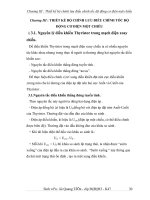
3.
Remove the ignition coil connectors(A) and ignition
coils(B).
Compression pressure: 1,176.79kPa (12.0kgf/cm²,
170.68psi) - 200 ~ 250rpm
Minimum pressure: 1,029.69kPa (10.5kgf/cm²,
149.34psi)
Difference between cylinders: 98.07kPa
(1.0kgf/cm², 14.22psi)
4)
A
B
6.
Reinstall the spark plugs.
7.
Install the ignition coils and connect ignition coil connectors.
8.
Install the surge tank.
B
C
SCMEM6001L
4.
Using a 16mm plug wrench, remove the 6 spark plugs.
5.
Check cylinder compression pressure.
1)
Insert a compression gauge into the spark plug
hole.
2)
Open the throttle fully.
3)
With the fully-open throttle in cranking, measure
the compression pressure.
NOTE
Always use a fully charged battery to get the engine
speed of 250 rpm or more.
Repeat steps 1) through 3) for each cylinder.
If the compression pressure in 1 or more cylinders is lower than the specification above, pour
a small amount of engine oil into the cylinder
through the spark plug hole, repeat the steps (1)
through (3) for the cylinder and measure the pressure again.
• If adding oil increases the pressure up, the
piston rings or cylinder bores might be worn
or damaged.
• If the pressure doesn’t increase, a valve may
be sticking or seating may be improper, or
there may be leakage from the gasket.
GENERAL
EMA -9
VALVE CLEARANCE INSPECTION AND
ADJUSTMENT
NOTE
Inspect and adjust the valve clearance when
the engine is cold (Engine coolant temperature :
20 C±5 C(59~77 F)) and cylinder head is installed
on the cylinder block.
1.
Remove the engine cover.
2.
Remove air cleaner assembly.
3.
Remove the surge tank.
4.
Remove the cylinder head cover.
1)
2)
KCBF119B
NOTE
Disconnect the ignition coil connector and remove the ignition coil.
Remove the cylinder head cover.
If not, turn the crankshaft one revolution clockwise.
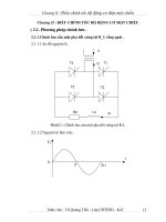
6.
Inspect the intake and the exhaust valve clearance.
1)
With the piston of the No.1 cylinder positioning
at TDC, the valves which can be measured its
clearance are as shown below.
RH EXHAUST
A
INTAKE
KCBF177A
5.
Set the piston of the No.1 cylinder to TDC(Top Dead
Center) position.
1)
2)
Turn the crankshaft pulley clockwise and align
its groove with the timing mark "T" of the timing
chain cover.
Check that the timing marks of the camshaft
sprocket are in straight line on that of the cylinder
head cover surface as shwn in the illustration. It
makes the piston of the No.1 cylinder position at
TDC.
LH EXHAUST
LDLG030A
Measurement method.
• Using a thickness gauge, measure the clearance between the tappet and the base circle
of camshaft.
• Record the out-of-specification valve clearance measurements. They will be used later
to determine the required adjusting tappet
for replacement.
Specification
Limit (Engine coolant temperature : 20 C [68 F])
Intake : 0.10 ~ 0.30mm (0.0039 ~ 0.0118in.)
Exhaust : 0.20 ~ 0.40mm (0.0079 ~ 0.0157in.)
EMA -10
ENGINE (G6EA - GSL 2.7)
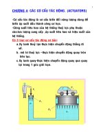
2)
Turn the crankshaft pulley one revolution (360 )
clockwise and align the groove with the timing
mark "T" of the timing chain cover.
3)
With the piston of the No.4 cylinder positioning
at TDC, the valves which can be measured its
clearance are as shown below.
RH EXHAUST
EDKE889D
INTAKE
7)
LH EXHAUST
LDLG031A
7.
Adjust the intake and the exhaust valve clearances.
1)
Set the piston of the No.1 cylinder to the TDC/position.
2)
Remove the timing belt.
3)
Remove the camshaft bearing caps(A, B).
Calculate the thickness of a new tappet so that
the valve clearance comes within the specified
value.
T : Thickness of removed tappet
A : Measured valve clearance
N : Thickness of new tappet
Intake : N = T + [A - 0.20mm(0.0079in.)]
Exhaust : N = T + [A - 0.30mm (0.0118in.)]
8)
Select a new tappet with a thickness as close as
possible to the calculated value.
NOTE
B
Tappets are available with 41different size increments
of 0.015mm (0.0006in.) from 3.00mm (0.118in.) to
3.600mm (0.1417in.)
9)
Place a new tappet on the cylinder head.
NOTE
Apply engine oil on the periphery surface of the selected tappet.
10) Install the intake and exhaust camshafts.
11) Install the bearing caps.
A
12) Install the timing belt.
KCBF169A
4)
Remove the camshaft assembly.
5)
Remove MLA(Mechanical Lash Adjuster)s.
6)
Measure the thickness of the removed tappet using a micrometer.
13) Turn the crankshaft two revolutions in the operating direction(clockwise) and realign crankshaft
sprocket and camshaft sprocket timing marks(A).
14) Recheck the valve clearance.
Specification (Engine coolant temperature: 20 C[68 F])
Intake : 0.17 ~ 0.23mm (0.0067 ~ 0.0090in.)
Exhaust : 0.27 ~ 0.33mm (0.0106 ~ 0.0129in.)
GENERAL
TROUBLESHOOTING
EMA -11
EAB59BFE
Symptom
Engine misfire with abnormal
internal lower engine noises.
Engine misfire with abnormal
valve train noise.
Engine misfire with coolant
consumption.
Engine misfire with excessive
oil consumption.
Engine noise on start-up, but
only lasting a few seconds.
Suspect area
Remedy
Worn crankshaft bearings.
Loose or impropes engine drive plate.
Replace the crankshaft and bearings
as required.
Repair or replace the drive plate
as required.
Worn piston rings.
(Oil consumption may or may not
cause the engine to misfire.)
Inspect the cylinder for a loss of
compression.
Repair or replace as required.
Worn crankshaft thrust bearings
Replace the crankshaft and bearings
as required.
Stuck valves.
(Carbon buildup on the valve stem)
Repair or replace as required.
Excessive worn or mis-aligned
timing chain.
Replace the timing chain and sprocket
as required.
Worn camshaft lobes.
Replace the camshaft and valve lifters.
• Faulty cylinder head gasket
and/or cranking or other damage
to the cylinder head and engine
block cooling system.
• Coolant consumption may or may
not cause the engine to overheat.
Worn valves, guides and/or valve
stem oil seals.
• Inspect the cylinder head and engine
block for damage to the coolant
passages and/or a faulty head gasket.
• Repair or replace as required.
Repair or replace as required.
Worn piston rings.
(Oil consumption may or may not
cause the engine to misfire)
• Inspect the cylinder for a loss
of compression.
• Repair or replace as required.
Incorrect oil viscosity.
• Drain the oil.
• Install the correct viscosity oil.
Worn crankshaft thrust bearing.
• Inspect the thrust bearing and
crankshaft.
• Repair or replace as required.
EMA -12
ENGINE (G6EA - GSL 2.7)
Symptom
Upper engine noise,regardless
of engine speed.
Suspect area
Low oil pressure.
Repair or replace as required.
Broken valve spring.
Replace the valve spring.
Worn or dirty valve lifters.
Replace the valve lifters.
Stretched or broken timing chain
and/or damaged sprocket teeth.
Replace the timing chain and sprockets.
Worn timing chain tensioner,
if applicable.
Replace the timing chain tensioner
as required.
Worn camshaft lobes.
Lower engine noise,regardless
of engine speed.
Remedy
• Inspect the camshaft lobes.
• Replace the timing camshaft and
valve lifters as required.
Worn valve guides or valve stems.
Inspect the valves and valve guides,then
repair as required.
Stuck valves. Carbon on the valve
stem or valve seat may cause the
valve to stay open.
Inspect the valves and valve guides,
then repair as required.
Worn drive belt, idler, tensioner
and bearing.
Replace as required.
Low oil pressure.
Repair as required.
Loose or damaged drive plate.
Repair or replace the drive plate.
Damaged oil pan, contacting the
oil pump screen.
• Inspect the oil pan.
• Inspect the oil pump screen.
• Repair or replace as required.
Oil pump screen loose, damaged
or restricted.
• Inspect the oil pump screen.
• Repair or replace as required.
Excessive piston-to-cylinder
bore clearance.
• Inspect the piston, piston pin
and cylinder bore.
• Repair as required.
Excessive piston pin-to-piston
clearance.
• Inspect the piston, piston pin and
the connecting rod.
• Repair or replace as required.
Excessive connecting rod bearing
clearance
Inspect the following components and
repair as required.
• The connecting rod bearings.
• The connecting rods.
• The crankshaft pin journals.
Excessive crankshaft bearing
clearance.
Inspect the following components,
and repair as required.
• The crankshaft bearings.
• The crankshaft main journals.
• The cylinder block.
Incorrect piston, piston pin and
connecting rod installation
• Verify the piston pins and connecting
rods are installed correctly.
• Repair as required.
GENERAL
Symptom
Engine noise under load.
Engine will not crank-crankshaft
will not rotate.
EMA -13
Remedy
Suspect area
Low oil pressure
Repair or replace as required.
Excessive connecting rod bearing
clearance .
Inspect the following components and
repair as required :
• The connecting rod bearings.
• The connecting rods.
• The crankshaft.
Excessive crankshaft bearing
clearance.
Inspect the following components,
and repair as required.
• The crankshaft bearings.
• The crankshaft main journals.
• The cylinder block.
Hydraulically locked cylinder.
• Coolant/antifreeze in cylinder.
• Oil in cylinder.
• Fuel in cylinder.
1.
2.
3.
4.
Remove spark plugs and check
for fluid.
Inspect for broken head gasket.
Inspect for cracked engine block
or cylinder head.
Inspect for a sticking fuel injector
and/or leaking fuel regulator.
Broken timing chain and/or timing
chain and/or timing chain gears.
1.
2.
Inspect timing chain and gears.
Repair as required.
Material in cylinder.
• Broken valve
• Piston material
• Foreign material
1.
Inspect cylinder for damaged
components and/or foreign materials.
Repair or replace as required.
Seized crankshaft or connecting
rod bearings.
1.
2.
2.
Inspect crankshaft and connecting
rod bearing.
Repair as required.
Bent or broken connecting rod.
1.
2.
Inspect connecting rods.
Repair as required.
Broken crankshaft.
1.
2.
Inspect crankshaft.
Repair as required.
EMA -14
SPECIAL TOOLS
ENGINE (G6EA - GSL 2.7)
EB132BF6
Tool (Number and name)
Illustration
Use
Crankshaft front oil seal installer
(09214-33000)
Installation of the front oil seal
EDKA010A
Torque angle adapter
(09221-4A000)
Installation of bolts
an angular method
nuts needing
LCAC030A
Valve stem seal remover
(09222-29000)
Removal of the valve stem seal
KDRF232A
Valve stem seal installer
(09222-22001)
Installation of the valve stem seal
LCAC030D
Camshaft oil seal installer
(09214-21000)
Installation of the camshaft oil seal
EDDA005B
GENERAL
EMA -15
Tool (Number and name)
Valve spring compressor
(09222-3K000)
(09222-3C300)
Illustration
Use
Removal and installation of the intake
or exhaust valves.
A : 09222-3K000
B : 09222-3C300 (holder)
holder
A
A
B
ECRF003A
Crankshaft rear oil seal installer
(09231-33000)
Installation of the crankshaft rear oil seal
LDLG032A
Oil pan remover
(09215-3C000)
Removal of oil pan
KDRF219A
Valve guide installer
(09221-3F100 A/B)
Removal and installation of the
valve guide
ECKA010B
EMA -16
ENGINE (G6EA - GSL 2.7)
ENGINE BLOCK
COMPONENTS
E98DF5AD
19.6(2.0, 14.5) + 90
18.6 ~ 23.5
(1.9 ~ 2.4, 13.7 ~ 17.4)
9.8 ~ 11.8
(1.0 ~ 1.2, 7.2 ~ 8.7)
TORQUE : N.m (kgf.m, lb-ft)
1.
2.
3.
4.
Piston ring
Piston
Piston
Connecting rod
5.
6.
7.
8.
Connecting rod bearing
Connecting rod cap
Upper oil pan
Lower oil pan
LDLG042A
ENGINE BLOCK
EMA -17
9.8 ~ 11.8
(1.0 ~ 1.2, 7.2 ~ 8.7)
1
4
2
11
3
5
7
6
8
9
10
29.4(3.0, 21.7) + 90 (M10)
15.7(1.6, 11.6) + 90 (M8)
TORQUE : N.m (kgf.m, lb-ft)
1.
2.
3.
4.
5.
6.
Rear oil seal
Rear oil seal case
Rear plate
Crankshaft upper bearing
Crankshaft
Lower thrust bearing
7.
8.
9.
10.
11.
Crankshaft lower bearing
Main bearing cap
Bearing cap bridge
Bearing cap bolt washer
Upper thrust bearing
LDLG043A
EMA -18
REMOVAL
1.
ENGINE (G6EA - GSL 2.7)
DISASSEMBLY
E2BF11E6
Remove the drive plate(A).
1.
EB2506EF
Remove the power steering pump bracket(A) and the
knock sensor(B).
A
B
A
KCBF120A
2.
Remove the rear plate(A).
KCBF122A
2.
Remove the air conditioning compressor bracket(A).
A
A
KCBF121A
3.
Remove timing belt.
4.
Remove intake manifold.
5.
Remove exhaust manifold.
6.
Remove generator from engine.(Refer to ’ST’ group).
7.
Remove power steering pump from engine.(Refer to
’HA’ group).
8.
Remove cylinder head.
9.
Remove A/C compressor from engine.(Refer to ’EE’
group).
KCBF138A
3.
Remove the lower oil pan(A).
A
10. Remove water pump assembly.
KCBF123A
ENGINE BLOCK
4.
EMA -19
10. Remove the oil seal case(A).
Remove the oil screen(A).
A
A
B
KCBF124A
5.
Remove the upper oil pan(A).
A
EDQF174B
11. Check the crankshaft end play.
12. Remove the crankshaft bearing cap and check oil
clearance.
09215-3C000
KCBF125B
CAUTION
When removing the oil pan, use the SST(092153C000) not to damage the contacting surface of
the oil pan.
6.
Check the connecting rod side clearance.
7.
Check the connecting rod bearing oil clearance.
8.
Remove the piston and connecting rod assemblies.
NOTE
• Keep the bearings the connecting rods and the
caps together.
• Arrange the piston and connecting rod assemblies in the correct order.
9.
Remove the oil pump case.
KCBF126A
NOTE
Arrange the bearings and the bearing caps in order.
EMA -20
ENGINE (G6EA - GSL 2.7)
13. Lift the crankshaft(A) out of the block, being careful
not to damage journals.
15. Remove the CKP sensor(A).
A
A
KCBF128A
16. Check the free play between a piston and a piston pin.
Try to move the piston back and forth on the piston
pin. If any movement is felt, replace the piston and
the piston pin as a set.
EDQF074A
17. Remove the piston rings.
14. Remove and arrange the main bearings and thrust
bearings in the correct order.
1)
Using a piston ring expander, remove the 2 compression rings.
2)
Remove the 2 side rails and the oil ring by hand.
NOTE
Arrange the piston rings in the correct order only.
A
18. Disconnect the connecting rod from the piston.
Using a press, remove the piston pin from the piston.
(Press-in load : 2451.7 ~ 12258.3N(250 ~ 1250kg,
551.2 ~ 2755.81lb)
EDQF076A
ENGINE BLOCK
INSPECTION
EMA -21
E3F92BD3
NOTE
Do not turn the crankshaft.
CONNECTING ROD AND CRANKSHAFT
1.
Check the connecting rod side clearance.
Using a feeler gauge, measure the side clearance
while moving the connecting rod back and forth.
7)
Remove the connecting rod cap again.
8)
Measure the plastigage at its widest point.
Standard oil clearance
0.018 ~ 0.036mm(0.0007 ~ 0.0014in.)
Specification
Standard : 0.1~ 0.25mm(0.0039 ~ 0.0098in.)
Limit : 0.4mm(0.0157in.)
EDQF175A
EDQF159A
9)
• If out-of-tolerance, install a new connecting rod.
• If still out-of-tolerance, replace the crankshaft.
2.
If the plastigage measures too wide or too narrow, remove the upper half of the bearing, install a new, complete bearing with the same color
mark (select the color as shown in the next column), and recheck the clearance.
Check the connecting rod bearing oil clearance.
1)
Check the matchmarks on the connecting rod
and cap are aligned to ensure correct reassembly.
2)
Remove the 2 connecting rod cap bolts.
3)
Remove the connecting rod cap and the lower
bearing.
4)
Clean the crankshaft pin journal and the bearing.
5)
Place a plastigage across the crankshaft pin.
6)
Reinstall the lower bearing and the connecting
rod cap and torque the bolts.
CAUTION
Do not file, shim, or scrape the bearings or the
caps to adjust clearance.
10) If the plastigage shows the clearance is still incorrect, try the next larger or smaller bearing (the
color listed above or below that one), and check
clearance again.
NOTE
If the proper clearance cannot be obtained by using
the appropriate larger or smaller bearings, replace the
crankshaft and start over.
CAUTION
Tightening torque
19.6Nm (2.0kgf.m, 14.46lb-ft) + 90
If the marks are indecipherable because of an accumulation of dirt and dust, do not scrub them
EMA -22
ENGINE (G6EA - GSL 2.7)
with a wire brush or scraper. Clean them only with
solvent or detergent.
CONNECTING ROD MARK LOCATION
DISCRIMINATION OF CRANKSHAFT
CLASS
MARK
OUTSIDE DIAMETER
OF PIN
I
1 or A
47.994 ~ 48.000mm
(1.8895 ~ 1.8898in.)
II
2 or B
47.988 ~ 47.994mm
(1.8893 ~ 1.8895in.)
III
3 or C
47.982 ~ 47.988mm
(1.8891 ~ 1.8893in.)
PLACE OF IDENTIFICATION MARK (CONNECTING
ROD BEARING)
EDQF196A
DISCRIMINATION OF CONNECTING ROD
CLASS
MARK
INSIDE DIAMETER
0
a
51.000 ~ 51.006mm
(2.0079 ~ 2.0081in.)
1
b
51.006 ~ 51.012mm
(2.0081 ~ 2.0083in.)
2
c
Color
51.012 ~ 51.018mm
(2.0083 ~ 2.0086in.)
ECRF021A
DISCRIMINATION OF CONNECTING ROD BEARING
CRANKSHAFT PIN MARK LOCATION
DISCRIMINATION OF CRANKSHAFT
EDQF176B
CLASS
MARK
THICKNESS OF
BEARING
A
BLUE
1.5000 ~ 1.503mm
(0.0591 ~ 0.0592in.)
B
BLACK
1.497 ~ 1.500mm
(0.0589 ~ 0.0591in.)
C
-
1.494 ~ 1.497mm
(0.0588 ~ 0.0589in.)
D
GREEN
1.491 ~ 1.494mm
(0.0587 ~ 0.0588in.)
E
YELLOW
1.488 ~ 1.491mm
(0.0586 ~ 0.0587in)
ENGINE BLOCK
EMA -23
11) Select the proper connecting rod bearing from
the table below.
Tightening torque
M8 : 15.7Nm(1.6 kgf.m, 11.6lb-ft) + 90
M10 : 29.4 Nm(3.0 kgf.m, 21.7lb-ft)+ 90
CONNECTING ROD
IDENTIFICATION MARK
CRANKSHAFT
INDENTIFICATION
MARK
3.
0(A)
1(B)
2(C)
I(A)
E
(YELLOW)
D
(GREEN)
C
(-)
II(B)
D
(GREEN)
C
(-)
B
(BLACK)
III(C)
C
(-)
B
(BLACK)
A
(BLUE)
NOTE
Tighten the bolts in order.
5)
Remove the cap and bearing again, and measure
the widest part of the plastigage.
Standard oil clearance
0.004~ 0.022mm (0.0002 ~ 0.0009in.)
Check the connecting rod.
1)
When reinstalling, check the cylinder numbers
on the connecting rods and the caps. When installing a new connecting rod, the notches for
bearing fixing on the connecting rods and caps
should face the same direction.
2)
If one or both edge of the connecting rod thrust
surface is damaged, replace the rod. If the inner
surface of the rod is damaged or rough, also replace it.
3)
Using a connecting rod aligner, measure the bent
or torsion of the rod. If the measurement is near
the specification, adjust the rod with a press. If
the rod is bent or twisted excessily, replace it.
Bending : 0.05mm/100mm(0.0020in./3.9370in.)
Torsion : 0.1mm/100mm(0.0039in./3.9370in.)
EDQF075A
6)
NOTE
When assembling the rod without a bearing, there
should be no difference.
4.
CAUTION
Check the crankshaft bearing oil clearance.
1)
To check main bearing-to-journal oil clearance,
remove the main bearing caps and bearing
halves.
If the plastigage measures too wide or too narrow, remove the upper half of the bearing, install a new, complete bearing with the same color
mark (select the color as shown in the next column), and recheck the clearance.
Do not file, shim, or scrape the bearings or the
caps to adjust clearance.
7)
2)
Clean each main journal and bearing half with a
clean shop tower.
If the plastigage shows the clearance is still incorrect, try the next larger or smaller bearing (the
color listed above or below that one), and check
clearance again.
3)
Place one strip of plastigage across each main
journal.
NOTE
4)
Reinstall the bearings and caps, then torque the
bolts.
If the proper clearance cannot be obtained by using
the appropriate larger or smaller bearings, replace the
crankshaft and start over.
EMA -24
ENGINE (G6EA - GSL 2.7)
CRANKSHAFT JOURNAL MARK LOCATION
CAUTION
If the marks are indecipherable because of an accumulation of dirt and dust, do not scrub them
with a wire brush or scraper. Clean them only with
solvent or detergent.
DISCRIMINATION OF CRANKSHAFT
Crankshaft bore mark location
Letters have been stamped on the block as a
mark for the each size of the 4 main journal bores.
No.1 journal stamping mark starts from the front
of the engine.
Use the size marks which are stamped on the
block and the crankshaft for the journal bore inner diameter and the journal outer diameter to
choose the correct bearings.
EDQF176A
DISCRIMINATION OF CRANKSHAFT
CLASS
MARK
OUTSIDE DIAMETER
OF JOURNAL
I
A
61.994 ~ 62.000mm
(2.4407 ~ 2.4409in.)
II
B
61.988 ~ 61.994mm
(2.4405 ~ 2.4407in.)
III
C
61.982 ~ 61.988mm
(2.4402 ~ 2.4405in.)
EDQF078A
DISCRIMINATION OF CYLINDER BLOCK
CLASS
MARK
INSIDE DIAMETER
a
A
66.000 ~ 66.006mm
(2.5984 ~ 2.5987in.)
b
B
66.006 ~ 66.012mm
(2.5987 ~ 2.5989in.)
c
C
66.012 ~ 66.018mm
(2.5989 ~ 2.5991in.)
PLACE OF IDENTIFICATION MARK (CRANKSHAFT
BEARING)
Color
ECRF022A
ENGINE BLOCK
EMA -25
DISCRIMINATION OF CRANKSHAFT BEARING
If the end play is greater than the maximum, replace
the center bearing.
MARK
THICKNESS OF
BEARING
A
BLUE
2.007 ~ 2.010mm
(0.0790 ~ 0.0791in.)
BLACK
2.004 ~ 2.007mm
(0.0789 ~ 0.0790in.)
6.
B
Inspect the main journals and the pin journals of the
crankshaft.
C
-
2.001 ~ 2.004mm
(0.0788 ~ 0.0789in.)
7.
Using a micrometer, measure the outer diameter of
each main journal and pin journal.
D
GREEN
1.998 ~ 2.001mm
(0.0787 ~ 0.0788in.)
E
YELLOW
1.995 ~ 1.998mm
(0.0785 ~ 0.0787in.)
CLASS
Thrust bearing thickness
1.925 ~ 1.965mm(0.0758 ~ 0.0774in.)
Main journal diameter : 61.982~ 62.000mm
(2.4402 ~ 2.4409in.)
Crank pin diameter : 47.982 ~ 48.000mm
(1.8891 ~ 1.8898in.)
SELECTION TABLE
CRANKSHAFT BORE
IDENTIFICATION MARK
CRANKSHAFT
IDENTIFICATION
MARK
5.
a(A)
b(B)
c(C)
I(A)
E
(YELLOW)
D
(GREEN)
C
(-)
II(B)
D
(GREEN)
C
(-)
B
(BLACK)
III(C)
C
(-)
B
(BLACK)
A
(BLUE)
Check crankshaft end play.
Using a dial indicator, measure the thrust clearance
while prying the crankshaft back and forth with a
screwdriver.
Standard end play
0.07 ~ 0.25mm (0.0028 ~ 0.0098in.)
[Limit]
0.3mm(0.0118in.)
KCRF212A
KCBF127A