Tài liệu Chapter 12: Brushless DC Motors pdf
Bạn đang xem bản rút gọn của tài liệu. Xem và tải ngay bản đầy đủ của tài liệu tại đây (322.86 KB, 14 trang )
Chapter 12. Brushless DC Motors
Topics to cover:
1. Structures and Drive Circuits
2. Equivalent Circuit
3. Performance
4. Applications
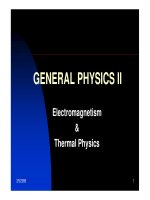
Introduction
Conventional dc motors are highly efficient and their characteristics make them suitable
for use as servomotors. However, their only drawback is that they need a commutator
and brushes which are subject to wear and require maintenance. When the functions of
commutator and brushes were implemented by solid-state switches, maintenance-free
motors were realised. These motors are now known as brushless dc motors.
In this chapter, the basic structures, drive circuits, fundamental principles, steady state
characteristics, and applications of brushless dc motors will be discussed.
Structures and Drive Circuits
Basic structures
The construction of modern brushless motors is very similar to the ac motor, known as
the permanent magnet synchronous motor. Fig.1 illustrates the structure of a typical
three-phase brushless dc motor. The stator windings are similar to those in a polyphase
ac motor, and the rotor is composed of one or more permanent magnets. Brushless dc
motors are different from ac synchronous motors in that the former incorporates some
means to detect the rotor position (or magnetic poles) to produce signals to control the
electronic switches as shown in Fig.2. The most common position/pole sensor is the
Hall element, but some motors use optical sensors.
Fig.1 Disassembled view of a brushless dc motor (from Ref.[1] p58 Fig.4.1)
48531 EMS – Chapter 12. Brushless DC Motors
Page 12-2
Logic
Circuit
DC
Supply
PM ac
Motor
Position
Sensor
Electronic Commutator
Fig.2 Brushless dc motor = Permanent magnet ac motor + Electronic commutator
Although the most orthodox and efficient motors are three-phase, two-phase brushless
dc motors are also very commonly used for the simple construction and drive circuits.
Fig.3 shows the cross section of a two-phase motor having auxiliary salient poles.
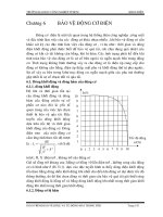
Comparison of conventional and brushless dc motors
Although it is said that brushless dc motors and conventional
dc motors are similar in their static characteristics, they
actually have remarkable differences in some aspects. When
we compare both motors in terms of present-day technology,
a discussion of their differences rather than their similarities
can be more helpful in understanding their proper
applications. Table 1 compares the advantages and
disadvantages of these two types of motors. When we
discuss the functions of electrical motors, we should not
forget the significance of windings and commutation.
Commutation refers to the process which converts the input direct current to alternating
current and properly distributes it to each winding in the armature. In a conventional dc
motor, commutation is undertaken by brushes and commutator; in contrast, in a
brushless dc motor it is done by using semiconductor devices such as transistors.
Fig.3 Two-phase motor
having auxiliary salient poles
(from Ref.[1] p95 Fig.5.22)
48531 EMS – Chapter 12. Brushless DC Motors
Page 12-3
Drive circuits
(1) Unipolar drive
Fig.4 illustrates a simple three-phase unipolar-operated motor that uses optical sensors
(phototransistors) as position detectors. Three phototransistors PT1, PT2, and PT3 are
placed on the end-plate at 120
o
intervals, and are exposed to light in sequence through a
revolving shutter coupled to the motor shaft.
As shown in Fig.4, the north pole of the rotor now faces the salient pole P2 of the stator,
and the phototransistor PT1 detects the light and turns transistor Tr1 on. In this state, the
south pole which is created at the salient pole P1 by the electrical current flowing
through the winding W1 is attracting the north pole of the rotor to move it in the
direction of the arrow. When the north pole comes to the position to face the salient pole
P1, the shutter, which is coupled to the shaft, will shade PT1, and PT2 will be exposed
to the light and a current will flow through the transistor Tr2. When a current flows
through the winding W2, and creates a south pole on salient pole P2, then the north pole
in the rotor will revolve in the direction of the arrow and face the salient pole P2. At this
moment, the shutter shades PT2, and the phototransistor PT3 is exposed to the light.
These actions steer the current from the winding W2 to W3. Thus salient pole P2 is de-
energized, while the salient pole P3 is energized and creates the south pole. Hence the
north pole on the rotor further travels from P2 to P3 without stopping. By repeating such
a switching action in sequence given in Fig.5, the permanent magnet rotor revolves
continuously.
Fig.4 Three-phase unipolar-driven brushless dc motor
(from Ref.[1] p59 Fig.4.2 with winding directions swapped)
48531 EMS – Chapter 12. Brushless DC Motors
Page 12-4
Fig.5 Switching sequence and rotation of stator's magnetic field
(from Ref.[1] p60 Fig.4.3)
(2) Bipolar drive
When a three-phase (brushless) motor is driven by a three-phase bridge circuit, the
efficiency, which is the ratio of the mechanical output power to the electrical input
power, is the highest, since in this drive an alternating current flows through each
winding as an ac motor. This drive is often referred to as 'bipolar drive'. Here, 'bipolar'
means that a winding is alternatively energised in the south and north poles.
We shall now survey the principle of the three-phase bridge circuit of Fig.6. Here too,
we use the optical method for detecting the rotor position; six phototransistors are
placed on the end-plate at equal intervals. Since a shutter is coupled to the shaft, these
photo elements are exposed in sequence to the light emitted from a lamp placed in the
left of the figure. Now the problem is the relation between the ON/OFF state of the
transistors and the light detecting phototransistors. The simplest relation is set when the
logic sequencer is arranged in such a way that when a phototransistor marked with a
certain number is exposed to light, the transistor of the same number turns ON. Fig.6
shows that electrical currents flow through Tr1, Tr4, and Tr5, and terminals U and W
have the battery voltage, while terminal V has zero potential. In this state, a current will
flow from terminal U to V, and another current from W to V as illustrated in Fig.7. We
may assume that the solid arrows in this figure indicate the directions of the magnetic
fields generated by the currents in each phase. The fat arrow in the centre is the resultant
magnetic field in the stator.
48531 EMS – Chapter 12. Brushless DC Motors
Page 12-5
Fig.6 Three phase bipolar-driven brushless motor (from Ref.[1] p61, Fig.4.4)
The rotor is placed in such a position that the field flux will have a 90
o
angle with
respect to the stator's magnetic field as shown in Fig.7. In such a state a clockwise
torque will be produced on the rotor. After it revolves through about 30
o
, PT5 is turned
OFF and PT6 ON which makes the stator's magnetic pole revolve 60
o
clockwise. Thus
when the rotor's south pole gets near, the stator's south pole goes away further to create a
continuous clockwise rotation. The ON-OFF sequence and the rotation of the transistor
are shown in Fig.8.
Fig.7 Stator's magnetic field in the shutter state of Fig.6, and the direction
of torque (from Ref.[1] p62, Fig.4.5)
Fig.8 Clockwise revolutions of the stator's magnetic field and rotor
(from Ref.[1] p63 Fig.4.6)