Tài liệu Industrial Circuits Application Note Microstepping pdf
Bạn đang xem bản rút gọn của tài liệu. Xem và tải ngay bản đầy đủ của tài liệu tại đây (320.5 KB, 9 trang )
1
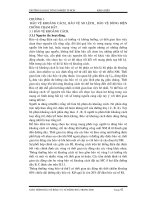
Figure 1. (A)—torque and speed ripple as function of load angle, full-step mode.
(B)—torque and speed ripple as function of load angle, microstepping
1
⁄
8
-full-step mode.
0.00
10.00
20.00
30.00
40.00
50.00
60.00
70.00
80.00
90.00
100.00
0.00 0.25 0.50 0.75 1.00 1.25 1.50
Load angle [degrees]
Motor torque [% of Thold]
Speed [full-steps/ms]
0.00
0.50
1.00
1.50
2.00
2.50
3.00
3.50
Time from first step [ms].
0.00
10.00
20.00
30.00
40.00
50.00
60.00
70.00
80.00
90.00
100.00
0.00
0.50
1.00
1.50
2.00
2.50
3.00
3.50
Load angle (fs-fr)
Torque
Speed
full-step mode
1/8-full-step mode
flux is rotated 90 and 45 electrical
degrees, respectively every step of the
motor. From the formula above we see
that a pulsing torque is developed by
the motor (see figure 1a, which also
shows the speed ripple caused by the
torque ripple). The reason for this is
that f
s
-f
r
is not constant in time due
to the discontinuous motion of f
s
.
Generating a stator flux that rotates
90 or 45 degrees at a time is simple,
just two current levels are required I
on
and 0. This can be done easily with all
type of drivers. For a given direction
of the stator flux, the current levels
corresponding to that direction are
calculated from the formulas:
I
A
=I
peak
× sin(f
s
)
I
B
=I
peak
× cos(f
s
)
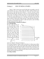
By combining the I
on
and 0 values
in the two windings we can achieve 8
different combinations of winding
currents. This gives us the 8 normal
1- and 2-phase-on stop positions cor-
responding to the flux directions 0,
45, …, 315 electrical degrees (see fig-
ure 2a).
If we have a driver which can gener-
ate any current level from 0 to 141%
of the nominal 2-phase-on current for
the motor, it is possible to create a
rotating flux which can stop at any
desired electrical position (see figure
2b). It is therefore also possible to
select any electrical stepping angle—
1
⁄
4
-full-step (15 electrical degrees),
1
⁄
8
-
full-step or
1
⁄
32
-full-step (2.8 electrical
degrees) for instance. Not only can the
direction of flux be varied, but also the
amplitude.
From the torque development for-
mula, we can now see that the effect of
microstepping is that the rotor will
have a much smoother movement on
low frequencies because the stator
flux, which controls the stable rotor
stop position, is moved in a more-con-
This application note discusses micro-
stepping and the increased system
performance that it offers. Some of the most
important factors that limit microstepping
performance, as well as methods of overcom-
ing these limitations, are discussed. It is
assumed that the reader is somewhat
familiar with stepper motor driving and
the torque generation principles of a stepper
motor. If not, chapter 1 and 2 of this book
can be read to get the background informa-
tion necessary.
What is microstepping
Microstepping is a way of moving the
stator flux of a stepper more smoothly
than in full- or half-step drive modes.
This results in less vibration, and
makes noiseless stepping possible
down to 0␣ Hz. It also makes smaller
step angles and better positioning
possible.
There are a lot of different micro-
stepping modes, with step lengths
from
1
⁄
3
-full-step down to
1
⁄
32
-full-
step—or even less. Theoretically it is
possible to use non-integer fractions of
a full-step, but this is often im-
practical.
A stepper motor is a synchronous
electrical motor. This means that the
rotor’s stable stop position is in syn-
chronization with the stator flux. The
rotor is made to rotate by rotating the
stator flux, thus making the rotor
move towards the new stable stop po-
sition. The torque (T) developed by
the motor is a function of the holding
torque (T
H
) and the distance between
the stator flux (f
s
) and the rotor posi-
tion (f
r
).
T=T
H
×sin(f
s
-f
r
)
where f
s
and f
r
are given in electrical
degrees.
The relationship between electrical
and mechanical angles is given by the
formula:
f
el
=(n÷
4)
× f
mech
where n is the number of full-steps per
revolution.
When a stepper is driven in full-
step and half-step modes the stator
Industrial Circuits Application Note
Microstepping
2
Figure 2. (A)—flux directions for normal half and full-step stop positions. Length is
proportional to holding torque. (B)—microstepping flux directions. Direction and length
are variable.
0
40
60
80
100
1/1
1/2 1/3
1/4 1/8 1/12
1/16
1/20
1/24
1/32
Step length relative to full-step.
0.120.21
0.310.48
0.86
1.9
7.6
13.4
29.2
100
20
% of full-step energy
tinuous way, compared to full and
half-step modes, (see figure 1b).
With frequencies above 2 to 3
times the system’s natural frequency,
microstepping has only a small effect
on the rotor movement compared to
full-stepping. The reason for this is
the filtering effect of the rotor and
load inertia. A stepper motor system
acts as a low pass filter.
Why microstepping
In many applications microstepping
can increase system performance, and
lower system complexity and cost,
compared to full- and half-step
driving techniques. Microstepping can
be used to solve noise and resonance
problems, and to increase step
accuracy and resolution.
Running at resonance frequencies
The natural frequency, F
0
(Hz), of a
stepper motor system is determined by
the rotor and load inertia,
J
T
=J
R
+J
L
(Kgm
2
), holding torque,
T
H
(Nm), (with the selected driving
mode and current levels) and number
of full-steps per revolution (n).
F
0
=(n×T
H
÷J
T
)
0.5
÷ 4π
If the system damping is low there
is an obvious risk of losing steps or
generating noise when the motor is
operated at or around the resonance
frequency. Depending on motor type,
total inertia, and damping; this prob-
lems can also appear at or close to
integer multiples and fractions of F
0
,
that is: …,
F
0
⁄
4
,
F
0
⁄
3
,
F
0
⁄
2
, 2F
0
, 3F
0
, 4F
0
,
… . Normally the frequencies closest
to F
0
gives the most problems.
When a non-microstepping driver
is used, the main cause of these reso-
nances is that the stator flux is moved
in a discontinuous way, 90 or 45 (full-
step and half-step mode) electrical
degrees at a time. This causes a
pulsing energy flow to the rotor. The
pulsations excite the resonance. The
energy transferred to the rotor, when a
single step is taken, is in the worst
case (no load friction) equal to:
(4T
H
÷ n) × [1 - cos(f
e
)]
T
H
and n are as above and f
e
= elec-
trical step angle, 90 degrees for full-
step, 45 degrees for half-step. This
shows that using half-steps instead of
full-steps reduce the excitation energy
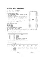
Figure 3. Relative excitation energy as function of electrical step length.
270°
225° 315°
180°
135°
100% 0°
I
A
141% 45°
I
B
90°
60% 300°
100% 90°
100% 215°
100% 170°
120% 110°
I
B
80% 350°
I
A
100% 10°
3
Electronic “gearbox”
In some applications, where small rel-
ative movements or higher step resolu-
tion are required, microstepping can
replace a mechanical gearbox. In many
applications, this is often a better and
less-complex solution—even if a larger
motor has to be used. To get the best
results in this type of application care-
ful motor selection and development
of customized sine/cosine profiles are
recommended.
Improved step accuracy
Microstepping can also be used to in-
crease stepper motor position accuracy
beyond the manufacturer’s specifica-
tion. One way to do this is as follows.
Design a microprocessor based micro-
stepping system. Use the motor at 2-
phase-on stop positions, |I
a
| = |I
b
|
(these are normally the most accurate
rotor stop positions). Use a factory
calibration process (manual or auto-
matic) to store a correction value for
each stop position on every motor
used. The correction value is used to
output “adjusted” full-step positions
to the motor (see figure 5b). The ad-
justed positions have slightly changed
current levels in the windings to com-
pensate for the position deviations at
the original stop positions (see figure
5a). This technique can be used when
optimum step accuracy is the most
important design criteria.
If this technique is used, the system
has to use a rotor home position indi-
cator to synchronize the rotor with the
compensation profile.
System complexity
Even though the electronics for gener-
ating microstepping is more complex
than electronics for full- and half-step-
to approximately 29% of the full-step
energy. If we move to microstepping
1
⁄
32
-full-step mode only 0.1% of the
full-step energy remains (see figure 3).
It appears that, by using micro-
stepping techniques, this excitation
energy can be lowered to such a low
level that all resonances are fully elim-
inated.
Unfortunately this is only true for
an ideal stepper motor. In reality
there are also other sources that excite
the system resonances. Never the less,
using microstepping will improve the
movement in almost all applica-
tions—and in many cases microstepp-
ing will alone give a sufficient reduc-
tion of the noise and vibrations to
satisfy the application.
Extending the dynamic range towards
lower frequencies
When running a stepper motor at low
frequencies. in half- or full-step mode.
the movement becomes discontinuous,
shows a great deal of ringing, and gen-
erates noise and vibrations. The step-
ping frequencies where this happens
are below the system’s natural fre-
quency. Here microstepping offers a
easy and safe way to extend noiseless
stepping frequencies down towards
0Hz. Normally it is not necessary to
use smaller steps than
1
⁄
32
-full-step.
With this small electrical step angle
the energy transferred to the rotor/
electrical step is only 0.1% of the full-
step energy, as described above, and is
so small that it is easily absorbed by
the internal motor friction—so no
ringing or overshot is generated by the
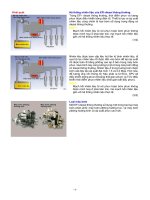
stepping (see figure 4). The deviation
of the microstepping positions from
a straight line is due to the use of un-
compensated sine/cosine profiles.
Figure 5. (A)—rotor and flux directions at
original full-step position. (B)—rotor and
flux directions at adjusted full-step position.
1
/
2
-step / Div.
25ms / Div.
Full-step mode
Microstepping
1
/
32
Figure 4. Rotor position as function of
stepping mode.
I
A
I
B
Flux 45°
Rotor 55°
I
A
Rotor 45°
I
I
B
Flux 35°
= 85%
A (new)
B (new)
I
= 116%
4
ping, the total system complexity in-
cluding motor, gearbox and transmis-
sion is less complex and costs less in
many applications. Microstepping can
replace or simplify gearboxes and me-
chanics for damping of noise and vi-
brations. Also motor selection be-
comes easier and more flexible.
In a microprocessor,based micro-
stepping application it is possible to
use software and PWM-timers or
D/A-converters internal to the micro-
processor to replace an external micro-
stepping controller to achieve lowest
possible microstepping hardware cost.
It is then possible to achieve the same
hardware cost as in full- and half-step
systems for similar motor sizes.
What affects microstepping
performance
In theory, microstepping is quite sim-
ple, and theoretically, the technique
solves all resonance, vibration and
noise problems in a stepper motor
system.
In reality, a lot of different phenom-
ena arise which set limits for the sys-
tem performance. Some are related to
the driver and others to the motor. If a
high-precision controller/driver
combination such as PBM 3960 and
PBL 3771 or equivalent are used, then
the errors associated with the driver
are negligible when compared with
those associated with most available
motors.
Step accuracy
In the manufacturers’ stepper motor
data sheets, the step accuracy is nor-
mally given. Step accuracy can be
given absolute (±1.0 degree, as an ex-
ample) or relative (±5% of one full-
step). Normally step accuracy is only
specified for 2-phase-on stop posi-
tions. (Here a 2-phase-on stop position
means a position with the same cur-
rent level in both windings. A posi-
tion with different current levels, or
none, in the windings is a microstep
position.) This means that the manu-
facturer does not tell anything about
the motor behavior when the motor is
used in a microstepping application.
Optimizing a motor for high full-step
positioning accuracy and holding
torque normally reduces micro-
stepping accuracy.
One important effect of the 2-
phase-on step accuracy is shown by the
following example. Consider a micro-
stepping design, using
1
⁄
32
-full-step
mode with a 7.5-degree PM-stepper
motor. One microstep theoretically
corresponds to 7.5 ÷ 32 = 0.23°. For
this type of motor a step accuracy of
±1 degree is common. This means
that if the motor home position is cali-
brated at a randomly-selected 2-phase-
on position (which can be positioned
anywhere within ±1 degree from the
theoretically-correct home position)
the maximum deviation of the rotor at
another 2-phase-on position can be
[1-(-1)] / 0.23 = 8.5 microsteps from
its theoretical position. This fact has
to be considered when microstepping
is used in applications were absolute
positioning is essential. A technique
to solve this problem is described pre-
viously under “Improved step accu-
racy”.
Sine⁄cosine conformity
Most actual stepper motors do not
have an ideal sine/cosine behavior (a
stepper with idealized sine/cosine be-
havior will rotate with a absolute con-
stant speed when a sine/cosine current
pair is applied to the windings). Main-
ly due to varying air gap area, air gap
distance and magnetic hysteresis the
flux vector direction and magnitude—
and therefore the microstepping stop
positions and the microstepping hol-
ding torque—deviate from the ideal
sine/cosine behavior. The deviations
are dependent upon rotor and stator-
tooth shape, and the type of material
used in the construction.
Some motors are optimized for high
holding torque or increased step accu-
racy at 2-phase-on stop positions. This
can be done by shaping the teeth in
such a way that a extra high flux is
achieved at the 2-phase-on positions.
This type of optimized motors should
be avoided in microstepping applica-
tions because there large deviations
from the sine/cosine behavior. The
closer the motor conforms to the sine/
cosine behavior the better performance
in a microstepping application.
The deviations can be divided into
two parts: of the amplitude of the flux
vector (influences the microstepping
holding torque), and of the direction
of the flux vector (effects the micro-
stepping stop positions).
Microstepping position ripple
When a stepper is used in a micro-
stepping application, the microstep-
ping stop positions are affected by the
sine/cosine conformity. The difference
between the theoretical and actual mi-
crostepping stop positions is called
microstepping position ripple. It is
defined as the average deviation, for all
full-step cycles over a full revolution,
of the actual microstep stop positions
from the theoretical, when a sine/
cosine current wave form is applied to
the motor windings (see figure 6). The
microstepping position ripple is a
median value over the whole revolu-
tion. This means that it is not a func-
tion of the normal 2-phase-on step
accuracy. To calculate the total micro-
stepping accuracy, the microstepping
position ripple has to be added to the
2-phase-on accuracy.
The effect of the microstepping po-
sition ripple is that, when a motor is
driven with an uncompensated sine/
cosine profile, the rotor movement
will show a varying speed over the
full-step cycle—in other words, the
microsteps will vary in length. Micro-
step lengths from
1
⁄
2
to 3 times the
nominal are not uncommon when a
microstep length of
1
⁄
32
-full-step is
used (see figure 7).
In microstepping applications, this
is most common phenomena that
excites the systems resonances.
Microstepping holding torque ripple
The magnitude of the magnetic flux
will also deviate from the theoretical
value when microstepping is applied
to a stepper motor. This is referred to
as microstepping holding torque
ripple. The nominal holding torque is
theoretically independent of the flux
direction when the motor is driven
with a sine/cosine current wave form.
The theoretical holding torque is cal-
culated from the formula:
T
H
=k×(I
A
2
+I
B
2
)
0.5
If I
A
and I
B
are sine/cosine pair then
T
H
is independent of flux direction.
The magnitude of the microstep-
ping holding torque ripple, which is a
function of the nominal stator and
rotor-tooth geometry, is normally in
the range 10 to 30% of the nominal
2-phase-on holding torque. Most
motors are optimized for highest
5
holding torque at the 2-phase-on
positions (see figure 8).
The microstepping holding torque
ripple is an average value for all full-
step cycles over one full revolution and
should not be confused with the
motor-tolerance-dependent 2-phase-
on holding torque ripple. When a
stepper is stopped at different 2-phase-
on positions the holding torque
normally differs up to ±10% of the
nominal holding torque. These
variations are caused by mechanical
tolerances in the rotor/stator geometry
of the motor and would be zero for a
geometrically correct motor.
Hysteresis
The stop-position hysteresis of a step-
per motor is mainly affected by the
magnetic hysteresis, but also partly by
the friction of the rotor bearing. If we
measure the microstep stop positions,
first by rotating the motor in CW di-
rection and then in the CCW direc-
tion the hysteresis will clearly show
(see figure 6).
The magnetic flux in the air gap is
theoretically proportional to the num-
ber of turns in the winding (n) and the
winding current (I).
F
A
=k
f
×n×I
Because of the hysteresis of the
magnetic materials in the rotor and
stator flux path, this is not quite true.
When hystereses are involved, the
present flux is a function of the
present winding current and the flux
history (see figure 9). The H value is
directly proportional to the winding
current, but to determine the flux it is
also necessary to know the previous H-
values (the flux history). In applica-
tions where positioning accuracy is
important, it is some times necessary
to use an over-shot movement so as to
always have the hysteresis on the same
side and thereby not create any addi-
tional positioning error.
In a high-resolution microstepping
application, the hysteresis can be sev-
eral times the nominal microstep
length.
When the total positioning accu-
racy of a stepper motor system is cal-
culated, it is important to know if the
hysteresis is included in the step accu-
racy given in the motor data sheet.
Figure 6. Microstepping position ripple for a 57mm 7.5 degree PM stepper.
CW ripple = 1.04 - (-0.61) = 1.65 degrees = 22%.
Figure 7. 57mm PM-stepper relative microstep length as function of stop position,
1
/
32
-
full-step mode.
Figure 8. Microstepping holding torque ripple for a 57mm PM stepper.
Ripple = 13.3 - -14.8 = 28.1%.
-2.00
-1.50
-1.00
-0.50
0.00
0.50
1.00
1.50
1 3 5 7 9 11 13 15 17 19 21 23 25 27 29 31
Microstep positions, 1 = 1-phase-on, 17 = 2-phase-on.
-0.61
1.04
-0.02
-1.65
Absolute deviation (degrees)
Clockwise
Counter-clockwise
-4.00
-3.00
-2.00
-1.00
0.00
1.00
2.00
3.00
4.00
1 3 5 7 9 1113151719212325272931
Microstep positions, 1 = 1-phase-on, 17 = 2-phase-on.
Relative Step length
Clockwise
Counter-clockwise
-20
-15
-10
-5
0
5
10
15
20
135791113151719212325272931
-14.8
13.3
Relative deviation (%)
Microstep positions, 1 = 1-phase-on, 17 = 2-phase-on.