Tài liệu Migrating from SCADA to Automation pdf
Bạn đang xem bản rút gọn của tài liệu. Xem và tải ngay bản đầy đủ của tài liệu tại đây (424.84 KB, 6 trang )
Migrating from SCADA to Automation
Abstract
--
.
This paper describes the City of Naperville’s
migration from a traditional SCADA system to an integrated
SCADA and Substation/Distribution Automation System. The
paper will examine:
•
Change Drivers that provided the impetus for the migration
•
The system design criteria and the architecture selected
•
Key features of the system and expected benefits
•
Value-added applications
•
The migration strategy that the City developed
Index Terms--
SCADA, substation automation, integration,
distribution automation, intelligent electronic devices, bay
controller, multi-function devices, PLC-based control, HMI.
I.
I
NTRODUCTION
The City of Naperville operates a Department of Public
Utilities, which includes a municipal electric utility.
Naperville’s electrical distribution system is nearly 90%
underground, except in older areas of town where overhead
facilities are still utilized. The nominal voltage of the system
is 12.47kV transformed from 34.5kV and 138kV. There are 6
points of service on the 138kV transmission system from bulk
power providerComEd. The City does not have generation
capability at this time.
TABLE I
Electric Department Statistics
Supply Source ComEd Wholesale Bulk Power at 6
Substations – Metering Locations
Substations 12 existing (4 Future)
Peak Monthly Demand (7/99) 317,680 Kilowatts
Peak Month Energy Use (7/99) 143.083 Million Kilowatt-hours
Distribution – Feeder Lines 116.59 Miles
Distribution - Sub Feeder Lines 108.72 Miles
Distribution – Primary 677.51 Miles
Transmission Lines 36.75 Miles
Customers - Total (12/00) 50,830
Rates/Residential $9.50/mo. customer charge plus 6.62
cents per kilowatt hour energy
charge
The service area includes 46 square miles of land within the
corporate limits of City of Naperville, which presently has a
D. Gacek and O. Geynisman are with the City of Naperville,
Naperville, IL 60566, and
D. Proudfoot and Kevin Minnick are with Siemens Power
Transmission and Distribution, Power Automation Division, Raleigh,
NC 27626-0503 USA, and
population of approximately 125,000 with an expected
population of 160,000.
II.
E
XISTING
P
RACTICES
A. SCADA System
The current platform for remote control and indication of the
City’s substations is an ACS 7000 SCADA System. The
SCADA software runs on the Hewlett-Packard variant of the
UNIX operating system know as HP-UX. Purchased in 1990,
the hardware has been systematically installed and the last of
the RTUs are scheduled for installation in the winter of 2001.
The SCADA system is modest by today’s standards. The HP
servers are no longer in production and the workstations are
operational but not Y2K compliant. Communication takes
place over a licensed 900Mhz data radio system operating at
9600 bps. That notwithstanding, the system performs well for
real-time remote indication and control and has been very
reliable. Personnel have developed the necessary skills to
keep the system running at the required level of performance.
B. Distribution Automation System
The City of Naperville’s Electric Utility is continually striving
to improve the reliability of the distribution system. It is the
current design philosophy to install distribution automation
equipment on all primary feeders, using a combination of
overhead and underground switchgear with automatic
reconfiguration capabilities.
The typical Distribution circuit design utilizes 600 Ampere
main looped feeders from different substations, which are
tapped at pad mounted switchgear to serve distribution loads.
The City normally uses a configuration of 3 switches - two
“Normally Closed” (one on each feeder) and a “Normally
Open” one to loop them. When a fault occurs on one feeder
segment, or power is lost to the circuit, distribution
automation equipment identifies the problem section and
reconfigures the circuit to minimize outage area.
The first Distribution Automation system was installed in
1998 as part of a pilot project. Since that time the City has
gradually deployed feeder automation on other circuits.
Existing distribution automation equipment utilizes S&C
Electric Company switchgear with EnergyLine Inc.
IntelliTEAM Controls. The IntelliTEAM controls perform
D. Gacek, Member, IEEE, O. Geynisman, Member, IEEE, Douglas Proudfoot, Kevin Minnick
0-7803-7287-5/01/$17.00 (C) 2001 IEEE
0-7803-7285-9/01/$17.00 (C) 2001 IEEE 343
Page 2 of 6
automated reconfiguration or sectionalizing of the feeders.
The controls process data locally and exchange information
with each other using peer-to-peer communications over a
spread-spectrum radio network.
In order to evaluate team operation, view real-time data,
review historical events, or change settings, operators are
required to access the controls locally.
C. System Integration
In short – none. Neither the existing SCADA nor
Distribution Automation systems are designed to integrate
third party equipment. As a consequence, the City has
functional silos with no mechanisms to integrate the data
contained in either.
III.
C
HANGE
D
RIVERS
The drivers that provided impetus to the adoption of the new
automation technology are summarized in a simple mantra –
Do more, with less, faster.
•
As with other users of disparate control and monitoring
systems, the City has started looking for ways to integrate
the databases of the various systems and eliminate data
silos.
•
More efficient utilization of resources through
“windshield time” reduction by enabling remote
diagnostics, maintenance and monitoring.
•
Improving service restoration, troubleshooting and
disturbance/fault/outage forensics
•
Expand the range of IEDs supported within the
substation without major modification to the existing
SCADA RTUs.
•
Add substation to distribution system automated
functionality in a decentralized manner
•
Add substation to substation automated functionality in a
decentralized manner.
The challenge has been to design a system that will
accommodate all of the above functionality using “off the
shelf” technology to ensure expandability and vendor
independence.
IV.
SCADA
VS
I
NTEGRATION VS
A
UTOMATION
Traditional substation design has segmented secondary
equipment into separate functional “compartments”. A
Remote Terminal Unit performs remote control and
monitoring, protective relays provide protection, strip charts
record metering data, meter-dials display volts and amps and
control handles and annunciator panels provide local control
and monitoring.
The industry has experienced significant change in design
philosophy over the last ten years. SCADA has been
supplemented, and in some cases replaced, by Integration and
Automation Systems. It is somewhat difficult to define strict
functional boundaries between the three systems and the
terms are very often used interchangeably. In the opinion of
the authors, the differences can be summarized as follows:
•
SCADA is responsible for providing amps, volts, watts,
CB status, etc. This is normally accomplished using a
RTU.
•
Integration systems provide the same data, typically
acquired from IEDs using legacy or industry standard
communications protocols. In some designs, the
integration system supplants the RTU, in others the RTU
is treated as another IED. In addition to the “traditional”
SCADA data, the Integration System also has access to
additional data like fault forensics, diagnostics,
maintenance, alarming etc, extracted from the IEDs. The
challenge is externalizing these data, and two choices are
available – map the data (somehow) into the SCADA
protocol the SCADA Control Center supports, or provide
a secondary link into the substation to access the data –
normally some form of broadband access.
•
Automation systems provide the same functionality as the
Integration System with one additional and
differentiating feature, namely the ability to turn data into
something meaningful and valuable.
What additional characteristics does a substation design have
to possess to be deemed an Automation system? It must be
capable of providing the following advanced, value-added
applications:
•
Protection and Process Automation
- the core
protection and control processes;
•
Maintenance Automation -
tools and tactics to employ
Reliability Centered Maintenance (RCM) and Just-in-
Time (JIT) Maintenance for transformers, breakers,
switches, CTs and VTs;
•
Information Automation -
the “art” of changing data to
information, trending, alarming, archiving and employing
expert decisions;
•
Information Distribution
- getting pertinent information
to where it can be used.
The City selected a system based on these criteria.
V.
T
HE
A
UTOMATION
S
YSTEM
The City selected the Siemens Power Transmission and
Distribution SICAM system. The system seamlessly
integrates the Protection, Control, Monitoring, Automation
and Visualization of the substation. The SICAM system
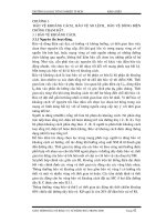
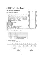
consists of the three level hierarchy depicted below:
0-7803-7287-5/01/$17.00 (C) 2001 IEEE
0-7803-7285-9/01/$17.00 (C) 2001 IEEE 344
Page 3 of 6
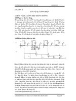
Fig. 1. System Architecture
A. Human Machine Interface
The
Human Machine Interface (HMI) Level
has four
components:
•
SICAM WinCC – Used by substation personnel to
Control and Monitor the system. It is responsible for
displaying SCADA data on one-line diagrams, for
trending data, for archiving data, and for issuing and
recording alarm messages. SICAM WinCC operates on
Windows NT and can be configured in a Client-Server
architecture so that multiple client PCs can access system
data.
•
SICAM PlusTools – Used by System Administrators to
configure the Substation Controller. It is responsible for
identifying which devices are part of the configuration,
configuring communications interfaces, specifying which
data are available from the devices, where the data has to
go, and any processing that has to be performed on the
data. SICAM PlusTools operates on Windows
95/98/NT.
•
SICAM RecPro – Used by Protection Personnel for post
fault forensics to analyze fault records after a system fault
has occurred. Fault records are automatically extracted,
appropriate alarm indications are generated. Protection
Personnel can use the intuitive GUI to navigate through a
summary of all system faults and drill-down into detailed
analysis of individual faults where desired.
•
DIGSI – Used by Protection Personnel for configuration,
maintenance and analysis of Siemens Relays and Bay
Controllers – either locally or remotely.
WinCC, PlusTools and RecPro interface with the SICAM
Substation Controller(s)
,
one level below the HMI level.
•
WinCC communicates with the Substation Controller(s)
on a continuous basis to get the latest metering,
measurement and status data. There can be up to two
WinCC Servers independently communicating to the
Substation Controller(s). Each WinCC Server can have
up to 32 Clients when operating in a Client-Server
configuration, or unlimited users when operating in a
Web hosting configuration.
•
PlusTools communicates with the Substation
Controller(s) on an ad hoc basis whenever configuration
changes are required. The architecture supports multiple
PCs running PlusTools.
•
RecPro communicates with the Substation Controller on
a periodic basis to check for fault records.
•
DIGSI communicates with the Relay(s) and Bay
Controller(s) on an ad hoc basis whenever configuration
changes or device analysis is required. The architecture
supports multiple PCs running DIGSI.
B. Substation Controller
The Substation Controller
Level
consists of the SICAM
Substation Controller. The Substation Controller combines
the best qualities of Programmable Logic Controllers
(modular design and powerful logic capabilities) and Remote
Terminal Units (ruggedized I/O and SCADA
communications). It is responsible for communicating with
the various Intelligent Electronic Devices (IEDs), processing
the data, passing pertinent data changes to the HMI and
managing any control requests from the HMI. It can also be
equipped with a variety of Input/Output (I/O) modules to
directly monitor and control plant data.
The primary tasks of the Substation Controller are:
•
Data concentration – it is responsible for communicating
with the substation relays and IEDs and performing
intelligent pre-processing and filtering of IED data
•
Safety and Security - performing interlocking of control
commands to ensure that controls are only executed
under safe conditions.
•
Miscellaneous I/O – controlling and monitoring any I/O
that are not available via the IEDs
•
Interfacing to the SCADA Control Center via DNP 3.0.
•
Interfacing to the existing downstream Distribution
Automation equipment via DNP 3.0
•
Advanced Automation Applications – Utilizing the PLC
logic and math capabilities, applications are developed
here to monitor, alarm, and control overall optimization
of the electric system and the system components
(transformers, breakers, switches, CTs, and VTs).
C. IEDs
The
IED Level
consists of Intelligent Electronic Devices.
The substation is divided into cells, or bays – with one feeder
per bay. Each bay is equipped with a Siemens Bay
Controller.
These Multi-Function IEDs are a combination protective
relay and RTU, which in addition to providing protection,
SCADA and metering data, also offer
•
A large graphical display that supports local control and
Level 2
Substation
Control Level
SICAM WinCC/PlusTools/Recpro/DIGSI
SICAM Substation Controller(s)
Protective Relays / Bay Controllers / Meters / Other IEDs
Level 3
HMI
Level 1
IEDs
0-7803-7287-5/01/$17.00 (C) 2001 IEEE
0-7803-7285-9/01/$17.00 (C) 2001 IEEE 345
Page 4 of 6
monitoring
•
Embedded IEC 1131 PLC logic that is used to implement
automation applications
•
Dual-redundant fiber LAN connectivity
D. Communications Architecture
To maximize performance and reliability, the City decided to
standardize on a
fiber Local Area Network
. The LAN is
configured as a dual-redundant ring to eliminate single point-
of-failure concerns. The LAN protocol employed is Profibus
FMS – a deterministic, Fieldbus protocol operating at
1.5Mbps.
The multi-master capabilities of the protocol allow
communications between the HMI, Substation Controller and
Bay Controllers to occur on the same fiber. In addition, it is
possible to perform other functions such as waveform
extraction, configuration changes, etc on the same LAN,
while the system is operational.
As the diagram illustrates, the Substation Controller and HMI
are connected to the City’s broadband WAN. The City will
utilize their WAN to run 10MBps Ethernet into each
substation. This facilitates intelligent alarming, email
notifications, remote forensics, remote reconfiguration, and
substation database management. In future, the peer-to-peer
communications capabilities of the Substation Controllers
over TCP/IP will allow the implementation of automation
schemes that require inter-substation communications.
Communications to the existing SCADA Control Center, and
third party IEDs (either locally or remotely located) is
accomplished via DNP 3.0.
VI.
K
EY
S
YSTEM
F
EATURES
A. Integrated System
Integration is very often taken to mean the ability to speak to
devices in their native protocol. The SICAM system offers a
higher level of integration, namely the
integration of the
configuration and operation of all three hierarchical
levels
.
The same configuration software is used to configure the
Substation Controller and Bay Controllers. After a Bay
Controller is added to the configuration, the Substation
Controller immediately knows about the device and the data it
possesses – this allows seamless
configuration inheritance
.
The same software also automatically populates the database
of the HMI. Configuration data is entered once, thereafter it
is automatically moved up the hierarchical layers, totally
eliminating the possibility of database mismatches due to
typographical errors – to say nothing of the time it saves.
In addition to making configuration/re-configuration/upgrades
easier, the integrated nature of the
system makes it possible
to
provide an array of value added applications not
feasible with conventional integration/automation
syste
ms.
B. Value Added Applications
The integrated nature of the SICAM System makes it possible
to offer the following categories of advanced, value-added
applications: Protection and Process Automation,
Maintenance Automation, Information Automation, and
Information Distribution.
Some examples of applications are:
•
Advanced Breaker Monitoring - monitor various breaker
timing sequences such as trip and close initiate to “a” and
“b”, I/t data and operations count, use of digital
oscillography to obtain an operational "fingerprint"
(normal operation), and use of oscillography for forensic
engineering after an alarm is asserted.
•
Advanced Transformer Monitoring and Control –
perform multi-variable analysis on measurements like
Top Oil temperature, ambient temperature, loading and
LTC position, and provide smart alarms and perform
controls based on dynamic interpretation of the data
•
Unified Sequence of Events for Rapid Fault Forensics –
all substation data events are time stamped and presented
to the operator in chronological sequence with the
associated time stamp (accurate to 1ms)
•
Unified Substation Volt/VAR Support - control voltage
and VAR support in substations (LTCs, regulators and
capacitor banks) using adaptive strategies.
•
Storm Mode Fuse-saving/blowing logic - Use input from
SCADA (storm, no storm) to change fuse-blowing logic
to improve SAIDI/SAIFI indices.
•
Load Shedding - Relay-centric or bus centric.
•
Automate Indices Reporting - compute and track all
performance indices for particular feeders.
•
Auto-documentation – automatically generate logic and
configuration documentation
C. Automatic Version Control
Any system that integrates IEDs, especially those that support
selective mapping of data, (i.e. where users have the ability to
select more or fewer data) are faced with the problem of
configuration mismatches. If you change the data profile of
an IED, all upstream devices are impacted, and must adjust
their databases accordingly. The SICAM system not only
performs this function automatically, it also checks the
version number of the configuration information prior to
going operational. If a new HMI is added to the system (for
example, to replace a failed unit), it checks to ensure that it
and the Substation Controller have the same version. If a
mismatch is detected, the system will notify the user that the
two systems need to be resynchronized. This
prevents
configuration mismatches
, eliminating the risk of mis-
operation.
In addition, the tedious (and time consuming) task of re-
configuring the system is performed automatically, and safely,
0-7803-7287-5/01/$17.00 (C) 2001 IEEE
0-7803-7285-9/01/$17.00 (C) 2001 IEEE 346
Page 5 of 6
making system enhancements quick and easy
.
D. Security
Security is a key feature of the system. In addition to
ensuring that database mismatches do not occur as described
above, the SICAM system allows the user to define
interlocking schemes to prevent mis-operation. If desired, all
control commands, whether issued by the remote SCADA
control center or the local HMI are passed through interlock
checks in the Substation Controller. Only if the control is
adjudicated as valid will it be issued to the relevant IED. In
addition to these system-wide interlock checks, bay-level
interlock checks can also be defined in the Bay Controllers.
System-wide interlock schemes that require inputs from
multiple IEDs are defeated in other systems as soon as
substation personnel issue controls from the IED face plate.
The SICAM system can be configured so that all control
commands entered via the Bay Controller face plate are first
routed to the Substation Controller for verification before
approval is issued. In this fashion, the SICAM system is able
to
eliminate mis-operation due to human error
.
E. Power and Performance
No paper penned by Engineers would be complete without
the obligatory references to gee-whiz technology, so here
goes:
•
The Substation Controller is Siemens’ latest generation
PLC employing Pentium CPU technology.
•
All modules are hot-swappable
•
All firmware is flashed and can be loaded in the field if
required
•
SICAM WinCC is object orientated, making screen
creation and display re-use quick and easy.
•
SICAM WinCC is an ActiveX container, allowing 3
rd
party controls to be used if desired.
•
SICAM WinCC supports smart objects, allowing custom
objects and their behavior to be defined.
•
The speed and deterministic nature of the Profibus
protocol provides system wide update times of one
second.
•
Both Substation Controller and Bay Controller support
an IEC 1131 compliant PLC programming interface
called Continuous Function Chart (CFC) which is a
powerful, graphically based environment.
F. System Openness
One of the City’s prerequisites was that the system be non-
proprietary and offer them the ability to add software and
equipment from any vendor. The system does this by
supporting open interfaces at multiple levels:
•
The SICAM WinCC supports ODBC
1
, DDE
2
and OPC
3
1
Open Database Connectivity (ODBC) is an industry standard
mechanism used to access historical data.
2
DDE - Dynamic Data Exchange (DDE) is a standard mechanism
provided by Windows that allows software applications to exchange
real-time data
that allow 3
rd
party software applications to access
Substation data, either locally or remotely via the WAN.
•
The SICAM WinCC can act as a Web Server. HTML
pages populated with Java applets can be created so that
substation data can be published on the intranet or
internet.
•
The SICAM WinCC supports a variety of protocols like
Modbus, Modbus plus, AB DH, etc that allows third
party controllers to interface to the HMI
•
The SICAM Substation Controller supports TCP/IP
connection(s) that can be used for peer-to-peer
communications, or to connect to other IT systems
wishing to access substation data.
•
The SICAM Substation Controller can act as a Web
Server – making status data available in HTML format
•
The SICAM Substation Controller supports DNP 3.0 or
IEC 60870-5-101 communications back to a remote
SCADA master should the city ever wish to upgrade the
SCADA link or provide a SCADA interface to another
entity.
•
The SICAM Substation Controller can integrate 3rd party
IEDs using DNP 3.0 or IEC 60870-5-103. Legacy IEDs
can be integrated into the system via a communications
gateway device.
VII.
D
ESIGN BENEFITS
The City expects the integrated nature of the SICAM system
to offer the following benefits:
1)
Reduction in the number of devices required with a
commensurate reduction in cost, physical size, wiring,
installation, engineering and maintenance.
2)
Shorter system recovery time after a disturbance
3)
Better utilization of installed capacity
4)
Simpler to design, faster to implement, easier to replicate
5)
Guaranteed repeatability of the automation system from
one substation to the next
6)
The elimination of integration problems and inter-vendor
finger pointing
7)
The ability to perform advanced applications that would
previously have required multiple devices with a single
device
8)
Reduction in the number of software tools from a
collection of disparate vendor unique tools to an
integrated software suite that performs all requisite
functionality.
9)
“Forward compatability”, providing protection against
technical obsolescence.
10)
The ability to distribute data collection, processing and
automated actions to the Bay Controllers resulting in
faster response times
11)
Less revenue loss caused by wrong settings and IED
malfunction
12)
Higher system reliability due to automation, integration
and adaptive settings
3
OPC (OLE for Process Control) is an industry standard that defines
how individual software components can interact and share data.
0-7803-7287-5/01/$17.00 (C) 2001 IEEE
0-7803-7285-9/01/$17.00 (C) 2001 IEEE 347