Tài liệu PLC Programming Methods and Applications P2 pptx
Bạn đang xem bản rút gọn của tài liệu. Xem và tải ngay bản đầy đủ của tài liệu tại đây (1023.96 KB, 20 trang )
Chapter 1 - Ladder Diagram Fundamentals
1-28
CR1 CR3
LS1A
CYCLE
RUN LATCH
CR2
CYCLE
LS1B
CR1
CR3
CR3
CYCLE LOCK
S1
LEFT
START
CR1
RUN
S2
RIGHT
START
TDR1
S1
S2
TDR1, 0.5s
ANTI-TIE DOWN
CR1
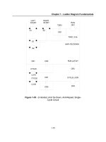
Figure 1-35 - 2-Handed, Anti-Tie Down, Anti-Repeat, Single-
Cycle Circuit
Chapter 1 - Ladder Diagram Fundamentals
1-29
1-5. Machine Control Terminology
There are some words that are used in machine control systems that have special
meanings. For safety purposes, the use of these words is explicit and can have no other
meaning. They are generally used when naming control circuits, labeling switch positions
on control panels, and describing modes of operation of the machine. A list of some of the
more important of these terms appears below.
ON This is a machine state in which power is applied to the machine and
to the machine control circuits. The machine is ready to RUN. This
is also sometimes call the STANDBY state.
OFF Electrically, the opposite of ON. Power is removed from the machine
and the machine control circuits. In this condition, pressing any
switches on the control panel should have no effect.
RUN A state in which the machine is cycling or performing the task for
which it is designed. This state can only be started by pressing RUN
switches. Don’t confuse this state with the ON state. It is possible for
a machine to be ON but not RUNNING.
STOP The state in which the machine is ON but not RUNNING. If the machine is
RUNNING, pressing the STOP switch will cause RUNNING to cease.
JOG A condition in which the machine can be “nudged” a small amount to
allow for the accurate positioning of raw material while the operator is
holding the material. The machine controls must be designed so that
the machine cannot automatically go from the JOG condition to the
RUN condition while the operator is holding the raw material.
INCH Same as JOG.
CYCLE A mode of operation in which the machine RUNs for one complete
operation and then automatically STOPs. Holding down the CYCLE
button will not
cause the machine to RUN more than one cycle. In
order to have the machine execute another CYCLE, the CYCLE
button must be released and pressed again. This mode is sometimes
called SINGLE CYCLE.
Chapter 1 - Ladder Diagram Fundamentals
1-30
2 HAND OPERATION
A control design method in which a machine will not RUN or CYCLE
unless two separate buttons are simultaneously pressed. This is used
on machines where it is dangerous to hand-feed the machine while it
is cycling. The two buttons are positioned apart so that they both
cannot be pressed by one arm (e.g., a hand and elbow). Both buttons
must be released and pressed again to have the machine start
another cycle.
1-6. Summary
Although this chapter gives the reader a basic understanding of conventional
machine controls, it is not intended to be a comprehensive coverage of the subject.
Expertise in the area of machine controls can best be achieved by actually practicing the
trade under the guidance of experienced machine controls designers. However, an
understanding of basic machine controls is the foundation needed to learn the
programming language of Programmable Logic Controllers. As we will see in subsequent
chapters, the programming language for PLCs is a graphic language that looks very much
like machine control electrical diagrams.
Chapter 1 - Ladder Diagram Fundamentals
1-31
Chapter 1 Review Questions
1. What is the purpose of the control transformer in machine control systems?
2. Whys are fuses necessary in controls circuits even though the power mains
may already have circuit breakers?
3. What is the purpose of the shrouded pushbutton actuator?
4. Draw the electrical symbol for a two-position selector switch with one contact.
The switch is named “ICE” and the selector positions are “CUBES” on the left
and “CRUSHED” on the right. The contact is to be closed when the switch
is in the “CUBES” position.
5. Draw an electrical diagram rung showing a N/O contact CR5 in series with
a N/C contact CR11, operating a lamp L3.
6. A delay-on (TON) relay has a preset of 5.0 seconds. If the coil terminals are
energized for 8 seconds, how long will its contacts be actuated.
7. If a delay-on (TON) relay with a preset of 5.0 seconds is energized for 3
seconds, explain how it reacts.
8. If a delay-off (TOF) relay with a preset of 5.0 seconds is energized for
1 second, explain how the relay reacts.
9. Draw a ladder diagram rung similar to Figure 1-30 that will cause a lamp L5
to illuminate when relay contacts CR1 is ON, CR2 is OFF, and CR3 is OFF.
10. Draw a ladder diagram rung similar to Figure 1-30 that will cause a lamp L7
to be OFF
when relay CR2 is ON or when CR3 is OFF. L7 should be ON at
all other times. (Hint: Make a table showing all the possible states of CR2
and CR3 and mark the combinations that cause L7 to be OFF. All those not
marked must be the ones when L7 is ON.)
11. Draw a ladder diagram rung similar to Figure 1-30 that will cause relay CR10
to energize when either CR4 and CR5 are ON, or when CR4 is OFF and CR6
is ON. Then add a second rung that will cause lamp L3 to illuminate 4
seconds after CR10 energizes.
Chapter 2 - The Programmable Logic Controller
2-1
Chapter 2 - The Programmable Logic Controller
2-1. Objectives
Upon completion of this chapter you will know
”
the history of the programmable logic controller.
”
why the first PLCs were developed and why they were better than the existing
control methods.
”
the difference between the open frame, shoebox, and modular PLC
configurations, and the advantages and disadvantages of each.
”
the components that make up a typical PLC.
”
how programs are stored in a PLC.
”
the equipment used to program a PLC.
”
the way that a PLC inputs data, outputs data, and executes its program.
”
the purpose of the PLC update.
”
the order in which a PLC executes a ladder program.
”
how to calculate the scan rate of a PLC.
2-2. Introduction
This chapter will introduce the programmable logic controller (PLC) with a brief
discussion of it's history and development, and a study of how the PLC executes a
program. A physical description of the various configurations of programmable logic
controllers, the functions associated with the different components, will follow. The chapter
will end with a discussion of the unique way that a programmable logic controller obtains
input data, process it, and produces output data, including a short introduction to ladder
logic.
It should be noted that in usage, a programmable logic controller is generally
referred to as a “PLC” or “programmable controller”. Although the term “programmable
controller” is generally accepted, it is not abbreviated “PC” because the abbreviation “PC”
is usually used in reference to a personal computer. As we will see in this chapter, a PLC
is by no means a personal computer.
Chapter 2 - The Programmable Logic Controller
2-2
2-3. A Brief History
Early machines were controlled by mechanical means using cams, gears, levers and
other basic mechanical devices. As the complexity grew, so did the need for a more
sophisticated control system. This system contained wired relay and switch control
elements. These elements were wired as required to provide the control logic necessary
for the particular type of machine operation. This was acceptable for a machine that never
needed to be changed or modified, but as manufacturing techniques improved and plant
changeover to new products became more desirable and necessary, a more versatile
means of controlling this equipment had to be developed. Hardwired relay and switch logic
was cumbersome and time consuming to modify. Wiring had to be removed and replaced
to provide for the new control scheme required. This modification was difficult and time
consuming to design and install and any small "bug" in the design could be a major
problem to correct since that also required rewiring of the system. A new means to modify
control circuitry was needed. The development and testing ground for this new means was
the U.S. auto industry. The time period was the late 1960's and early 1970's and the result
was the programmable logic controller, or PLC. Automotive plants were confronted with
a change in manufacturing techniques every time a model changed and, in some cases,
for changes on the same model if improvements had to be made during the model year.
The PLC provided an easy way to reprogram the wiring rather than actually rewiring the
control system.
The PLC that was developed during this time was not very easy to program. The
language was cumbersome to write and required highly trained programmers. These early
devices were merely relay replacements and could do very little else. The PLC has at first
gradually, and in recent years rapidly developed into a sophisticated and highly versatile
control system component. Units today are capable of performing complex math functions
including numerical integration and differentiation and operate at the fast microprocessor
speeds now available. Older PLCs were capable of only handling discrete inputs and
outputs (that is, on-off type signals), while today's systems can accept and generate analog
voltages and currents as well as a wide range of voltage levels and pulsed signals. PLCs
are also designed to be rugged. Unlike their personal computer cousin, they can typically
withstand vibration, shock, elevated temperatures, and electrical noise to which
manufacturing equipment is exposed.
As more manufacturers become involved in PLC production and development, and
PLC capabilities expand, the programming language is also expanding. This is necessary
to allow the programming of these advanced capabilities. Also, manufacturers tend to
develop their own versions of ladder logic language (the language used to program PLCs).
This complicates learning to program PLC's in general since one language cannot be
learned that is applicable to all types. However, as with other computer languages, once
the basics of PLC operation and programming in ladder logic are learned, adapting to the
various manufacturers’ devices is not a complicated process. Most system designers
Chapter 2 - The Programmable Logic Controller
2-3
eventually settle on one particular manufacturer that produces a PLC that is personally
comfortable to program and has the capabilities suited to his or her area of applications.
2-4. PLC Configurations
Programmable controllers (the shortened name used for programmable logic
controllers) are much like personal computers in that the user can be overwhelmed by the
vast array of options and configurations available. Also, like personal computers, the best
teacher of which one to select is experience. As one gains experience with the various
options and configurations available, it becomes less confusing to be able to select the unit
that will best perform in a particular application.
Basic PLCs are available on a single printed circuit board as shown in Figure 2-1.
They are sometimes called single board PLCs or open frame PLCs. These are totally
self contained (with the exception of a power supply) and, when installed in a system, they
are simply mounted inside a controls cabinet on threaded standoffs. Screw terminals on
the printed circuit board allow for the connection of the input, output, and power supply
wires. These units are generally not expandable, meaning that extra inputs, outputs, and
memory cannot be added to the basic unit. However, some of the more sophisticated
models can be linked by cable to expansion boards that can provide extra I/O. Therefore,
with few exceptions, when using this type of PLC, the system designer must take care to
specify a unit that has enough inputs, outputs, and programming capability to handle both
the present need of the system and any future modifications that may be required. Single
board PLCs are very inexpensive (some less than $100), easy to program, small, and
consume little power, but, generally speaking, they do not have a large number of inputs
and outputs, and have a somewhat limited instruction set. They are best suited to small,
relatively simple control applications.
Chapter 2 - The Programmable Logic Controller
2-4
Figure 2-1 - Open Frame PLC
(Triangle Research Inc., Pte. Ltd.)
PLCs are also available housed in a single case (sometimes referred to as a shoe
box) with all input and output, power and control connection points located on the single
unit, as shown in Figure 2-2. These are generally chosen according to available program
memory and required number and voltage of inputs and outputs to suit the application.
These systems generally have an expansion port (an interconnection socket) which will
allow the addition of specialized units such as high speed counters and analog input and
output units or additional discrete inputs or outputs. These expansion units are either
plugged directly into the main case or connected to it with ribbon cable or other suitable
cable.