Tài liệu ANSYS Mechanical- A Powerful Nonlinear Simulation Tool pdf
Bạn đang xem bản rút gọn của tài liệu. Xem và tải ngay bản đầy đủ của tài liệu tại đây (4.77 MB, 39 trang )
ANSYS Mechanical—A Powerful Nonlinear
Simulation Tool
Grama R. Bhashyam
1
Corporate Fellow, Development Manager
Mechanics & Simulation Support Group
ANSYS, Inc.
275 Technology Drive
Canonsburg, PA 15317
September 2002
1
With grateful acknowledgment to Dr. Guoyu Lin, Dr. Jin Wang and Dr. Yongyi Zhu for their input.
2
Executive Summary
Numerical simulation plays an indispensable role in the manufacturing process,
speeding product design time while improving quality and performance. Recently,
analysts and designers have begun to use numerical simulation alone as an acceptable
means of validation. In many disciplines, virtual prototyping—employing numerical
simulation tools based on finite element methods—has replaced traditional build-and-
break prototyping. Successful designs leading to better prosthetic implants, passenger
safety in automotive crashes, packaging of modern electronic chips, and other advances
are partly a result of accurate and detailed analysis.
Can one reliably simulate the collapse of a shell, interaction of multiple parts,
behavior of a rubber seal, post-yield strength of metals, manufacturing process and so on
using linear approximation? The answer is not really. With the trend toward ever-
improving simulation accuracy, approximations of linear behavior have become less
acceptable; even so, costs associated with a nonlinear analysis prohibited its wider use in
the past. Today, rapid increases in computing power and concurrent advances in analysis
methods have made it possible to perform nonlinear analysis and design more often while
minimizing approximations. Analysts and designers now expect nonlinear analysis
capabilities in general-purpose programs such as ANSYS Mechanical.
ANSYS, Inc. is a pioneer in the discipline of nonlinear analysis. The ANSYS
Mechanical program’s nonlinear capabilities have evolved according to emerging
analysis needs, maturity of analysis methods and increased computing power. The
program’s nonlinear analysis technology has developed at such a rapid pace that some
may be largely unaware of recent enhancements.
All of the following components are necessary for a reliable nonlinear analysis
tool: (a) element technologies for consistent large-deformation treatment, (b) constitutive
models for a variety of metals and nonmetals, (c) contact interaction and assembly
analysis, (d) solution of large-scale problems (where multiple nonlinearities interact in a
complex manner), and (e) infrastructure.
This paper presents a summary of the ANSYS Mechanical program’s nonlinear
technology. It is impossible given the scope of the paper to address every available
analysis feature; rather, the paper highlights key features of interest to most analysts and
designers and unique to the ANSYS Mechanical program. ANSYS, Inc. invites current
and potential ANSYS Mechanical users to explore the program’s capabilities further.
3
ANSYS Elements: Building Blocks of Simulation
The element library of Release 5.3 (circa 1994) was diverse and comprehensive in
its capabilities. A clear need existed, however, for a new generation of elements to
address the growing needs of multiplicity in material models and application
complexities, and to bring about a higher level of consistency. ANSYS, Inc.’s Mechanics
Group set out to develop a small set of elements (the 180 series) having these
characteristics:
• Rich functionality
• Consistency with theoretical foundations employing the most advanced
algorithms
• Architectural flexibility.
The application of conventional isoparametric fully integrated elements is limited.
In linear or nonlinear analyses, serious locking may occur. As a general analysis tool,
ANSYS Mechanical uses elements in wide range of applications. The following factors
influence the selection of elements:
• Structural behavior (bulk or bending deformation)
• Material behavior (nearly incompressible to fully incompressible).
The indicated factors are not necessarily limited to nonlinear analysis; however,
nonlinear analysis adds to the complexity. For example, an elasto-plastic material shows
distinctly different patterns of behavior in its post-yield state. While it is feasible given
today’s state of the art to provide a most general element technology that performs
accurately in virtually every circumstance, it will likely be the most expensive solution as
well. Analysts and designers make such engineering decisions routinely according to
their domain expertise, and their decisions often result in noticeable savings in
computational costs.
With that in mind, ANSYS, Inc. views its element library as a toolkit of
appropriate technologies. ANSYS, Inc. continues to develop and refine its element
technologies to make ANSYS Mechanical an increasingly powerful tool for finite
deformation analysis. Descriptions of existing element technologies follow.
Selective Reduced Integration Method
Also known as the Mean Dilation Method, B-Bar Method and Constant Volume
Method, the Selective Reduced Integration Method was developed for some lower order
solid elements to prevent volumetric locking in nearly incompressible cases. This
formulation replaces volumetric strain at the Gauss integration points with an average
volumetric strain of the elements.
4
Enhanced Strain Methods
A closer inspection of the ANSYS Mechanical program’s element library (even at
Release 5.2, circa 1993) provides evidence of ANSYS, Inc.’s early analysis leadership.
For example, incompatible mode formulation was adapted in all first-order solid elements
by default to avoid spurious stiffening in bending-dominated problems. The elements are
said to have “extra shapes” formulation in ANSYS documentation.
A more general form of enhanced strain formulation was introduced at Release
6.0. The formulation modifies deformation gradient tensor and strains in lower order
elements to prevent shear and volumetric locking (in nearly incompressible applications).
The formulation is robust and is perhaps the best option when the deformation pattern
may not be judged a priori as bulk or bending dominated.
Uniform Reduced Integration Method
The uniform reduced integration method prevents volumetric locking in nearly
incompressible cases and is usually more efficient. In lower-order elements, this method
can also overcome shear locking in bending-dominated problems. Hourglass control is
incorporated, as necessary, to prevent the propagation of spurious modes. Such
hourglassing is a non-issue in higher-order elements, provided that the mesh contains
more than one element in each direction. This formulation also serves well as a
compatible offering with our explicit offering, ANSYS LS-DYNA.
Displacement and Mixed u-P formulations
The ANSYS Mechanical program has both pure displacement and mixed u-P
formulations. Pure displacement formulation has only displacements as primary
unknowns and is more widely used because of its efficiency. In mixed u-P formulation,
both displacements and hydrostatic pressure are taken as primary unknowns.
In the newly developed 180-series elements, the different element technologies
can be used in combination (for example, B-bar with mixed u-P, enhanced strain with
mixed u-P, etc.). Table 1 provides a summary of the available technologies.
ANSYS Mechanical has both penalty-based and Lagrangian multiplier-based
mixed u-P formulations. Penalty-based formulation is meant only for nearly
incompressible hyperelastic materials. On the other hand, the Lagrange multiplier-based
formulation is available in the 180-series solid elements, and is meant for nearly
incompressible elasto-plastic, nearly incompressible hyperelastic and fully
incompressible hyperelastic materials.
5
The ANSYS Mechanical mixed u-P formulation (180-series) is user-friendly. It
switches automatically among different volumetric constraints according to different
material types. When used with enhanced strain methods, it excludes the enhanced terms
for preventing volumetric locking to get higher efficiency because the terms are
redundant in such a case. Provided that the material is fully incompressible hyperelastic,
ANSYS Mechanical activates the mixed u-P formulation of 180-series solid elements
even if the user does not specify it. The future promises even more automated,
application-specific selection of appropriate element technology.
Structural Elements
The ANSYS Mechanical program supports a large library of beam and shell
elements with wide applicability: composites, buckling and collapse analysis, dynamics
analysis and nonlinear applications.
Most commercial FEA packages have a discrete-Kirchhoff Theory-based shell
element employing an in-plane, constant-stress assumption. ANSYS Mechanical is
unique, however, offering this capability with Allman rotational DOF, and enhancement
of membrane behavior when used as a quadrilateral. The result is significantly higher
stress-prediction accuracy. The element supports small-strain, large-rotation analysis with
linear material behavior.
Some recent enhancements in the 180-series elements for structural applications
advance the state of the art. One can now expect both robust performance and ease of use.
The beam elements (BEAM188 and BEAM189) represent a significant move
towards true “reduction in dimensionality” of the problem (as opposed to simple beams).
Whether one employs a simple circular cross section or a complex arbitrary cross section,
a finite element cross-section analyzer calculates inertias, shear centers, shear flow,
warping rigidity, torsion constant, and shear correction factors. ANSYS Mechanical 2-D
modeling can sketch the arbitrary profiles. The section solver relies on the industrial
Plane Stress
Plane Strain
Axisymmetric
Generalized
Plane Strain
3D
Selective
Resuced
Inte
gration/B-Bar
Uniform Reduced
Integration
Enhanced Strain
Displacement
Mixed u/P
(nearly)
Mixed u/P (fully)
PLANE182 4 2D Quad. Low/Linear Bilinear • • • • • • • • • •
PLANE183 8 2D Quad. High/Quad Seren. • • • • • • • •
SOLID185 8 3D Brick Low/Linear Trilinear • • • • • • •
SOLID186 20 3D Brick High/Quad Seren. • • • • •
SOLID187 10 3D Tet. High/Quad Tet • • • • •
Table 1. Solid Element Technology Summar
y
18x Solid Elements
Numbers of Nodes
Interpolation
Element TechnologiesStress States Formulation Options
Dimensions
Element Shapes
Element Order
6
strength sparse solver, and hence the ability for solving large user-specified cross
sections.
It is possible to specify the mesh quality for the section solution. The cross
sections can also be comprised of a number of orthotropic materials, allowing for analysis
of sandwich and built-up cross sections. ANSYS, Inc. is aware of an extreme application
where a user modeled an entire rotor cross section using thousands of cells with tens of
materials. The beam elements complement the finite deformation shell elements very
well. The formulation employed allows for conventional unrestrained warping, and
restrained warping analysis as well. The generality of formulation is such that the user is
spared from details (such as selecting element types based on open or closed cross
sections) and limitations found elsewhere (for example, multiple cells, a circular tube
with fins). The robust solution kernel is complemented by the easy-to-use Beam Section
Tool and full 3-D results visualization. All elastoplastic, hypo-viscoelastic material
models may be used. It is an ideal tool for aerospace, MEMS, ship building, civil
applications, as illustrated:
Flexibility in cross section modeling
Composite rotor cross
section
A typical MEMS cross
section
An I-Section made of three
materials
Reinforced beam and a
sandwich cross section
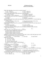
It is important to understand that no significant performance compromise exists
for linear analysis despite the overwhelming generality. This is valid for all 180-series
elements. Figure 1 shows the typical accuracy that one can achieve while enjoying the
benefits of a reduced dimensionality model.
7
BEAM189 (NDOF=96) BEAM189
(NDOF=192)
SOLID186
(NDOF=18900)
Max. displacement Value % diff. Value % diff. Reference value
Ux 19.664 0.2 19.666 0.2 19.625
Uy 24.819 1.9 24.822 1.9 25.310
Uz 54.486 0.5 54.490 0.5 54.769
CPU Time 82.610 115.460 4587.850
x
y
4
R
W2
W1
W3
t1
t2
t3
Figure 1. Nonlinear analysis of a curved beam with multiple
materials in cross section: a comparison of solid elements
Mat
Mat
In an upcoming release, beam section capability will allow a geometrically exact
representation of tapered beams (rather than an approximate variation of gross section
properties).
Similarly, the 180-series shell element SHELL181 offers state-of-the-art element
technology, be it linear or nonlinear analysis with strong emphasis on ease of use. The
four-node shell element is based on Bathe-Dvorkin assumed transverse shear treatment,
coupled with uniform reduced integration or full integration with enhancement of
membrane behavior using incompatible modes. Several elasto-plastic, hyperelastic,
viscoelastic material models can be employed. The element supports laminated
composite structural analysis, with recovery of interlaminar shear stresses. With this and
other shell elements, ANSYS also empowers users with a detailed submodel analysis
using solid elements for delamination and failure studies.
Figure 2 shows a model of a circular plate having thickness which varies with a
known formula; one can create such a model interactively via the ANSYS Mechanical
Function Builder. The shell element definition is therefore completely independent of
meshing and enhances accuracy by directly sampling thicknesses at element Gauss
points.
8
SHELL181 applicability encompasses frequency studies, finite strain/finite
rotation, nonlinear collapse, and springback analysis following an explicit forming
operation. The ANSYS Mechanical contact elements work with SHELL181 to allow
straightforward inclusion of current shell thickness in a contact analysis.
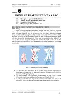
Figure 3 shows a beverage can in nonlinear collapse study, and Figure 4 shows a
stamped part which was analyzed for springback effects using the shell element.
Figure 3. Nonlinear collapse study of a
beverage can
Figure 4. Stamping (ANSYS LS-DYNA)
and springback analysis (ANSYS
Mechanical)
Common Features
ANSYS Mechanical data input can be parametric, allowing for parametric study
and optimization of structures. In the near future, the ANSYS Mechanical element library
will incorporate the power of CADOE variational analysis. The resulting combination
Figure 2. Circular tapered plate using Function Builder
9
offers promising opportunities including “what-if” studies, design sensitivity analysis,
and discrete and continuous optimization.
ANSYS Mechanical was foremost in offering submodeling, layered solid
elements advancing the state of art in composites analysis. In addition, rigid spars, rigid
beam, shell-to-solid interfaces, slider constraints will be available in the near future.
Interface elements simulate gasket joints or interfaces in structural assembly. Surface
elements apply various loading. Superelement and infinite elements are also available in
the ANSYS Mechanical element library.
Consistent and complete derivation of tangent stiffnesses is crucial for acceptable
convergence rates. For example, the effect of pressure loads to the stiffness matrix is
included by default in the 180-series elements.
The stress states supported in solid elements include: 3-D, plane stress, plane
strain, generalized plane strain, axisymmetric and axisymmetric with asymmetric loading.
The 180-series elements are applicable to all material models.
The ANSYS Mechanical program automatically selects appropriate shape
functions and integration rules when elements are degenerated. If necessary, it may
update the element technology specification. For example, when a quadrilateral element
degenerates into a triangle or a hexahedron element into a prism, pyramid or tetrahedral
forms, ANSYS Mechanical employs appropriate shape functions for displacement
interpolation and hydrostatic pressures instead of the generic shape functions for the
native element. The capability of the program to compensate for element degeneration
makes element formation less sensitive to mesh distortion and more robust in geometric
nonlinear analysis. The mid-side nodes at higher element can be omitted so that they can
be used as the transition elements. Degenerated shapes make modeling an irregular area
or volume easier
2
.
The 180-series family of elements offers superior performance and functionality.
They have provided an architecture for future advancements in material modeling,
including shape memory alloys, bio-medical, microelectronics assemblies, and
electronics packaging industrial needs. ANSYS, Inc. intends to support
remeshing/rezoning, fracture mechanics, variational analysis, and coupled fields in future
ANSYS Mechanical releases. ANSYS, Inc. development is also committed to making
further infrastructural improvements in the 180-series elements to accommodate
distributed processing needs. ANSYS, Inc. believes that such developments can simplify
and even automate element selection in future releases.
2
Degenerated element support for the 180-series of elements is a prerelease feature in Release 7.0.
10
Material Nonlinearity in ANSYS Mechanical
For engineering design and application, it is essential to understand and accurately
characterize material behavior. It is a challenging, complex science. Lemaitre and
Chaboche
3
express the complexity in a dramatic manner, as follows:
“A given piece of steel at room temperature can be considered to be:
Linear elastic for structural analysis,
Viscoelastic for problems of vibration damping,
Rigid,
Perfectly plastic for calculation of the limit loads,
Hardening elastoplastic for an accurate calculation of the permanent
deformation,
Elastoviscoplastic for problems of stress relaxation,
Damageable by ductility for calculation of the forming limits,
Damageable by fatigue for calculation of the life-time.”
Validity of the different models can be judged only on phenomenon of interest for
a given application. (See Table 2 for plasticity models.)
The scope and intent of this paper make it necessary to omit the details of material
models. ANSYS, Inc. encourages the reader to research standard references
4,5
and the
ANSYS Theory Guide.
3
Lemaitre and Chaboche, Mechanics of solid materials, Cambridge University Press, 1990
4
Simo, J.C. and Hughes, T.J.R., Computational inelasticity, Springer-Verlag, 1997
5
Ogden, R.W., Non-linear elastic deformations, Dover Publications, Inc., 1984.
Table 2. Validity of Plasticity Models*
Models
Monotonic
Hardening
Bauschinger
Effect
Cyclic
Hardening
or Softening
Ratchetting
Effect
Memory
Effect
Prandtl-Reuss
• •
Linear Kinematic
• •
Mroz
• • •
Nonlinear Kinematic
• • •
Kinematic+Isotropic
• • • •
Kinematic+Isotropic+memory
• • • • •
*Lemaitre and Chaboche, 1990
11
ANSYS provides constitutive models for metals, rubber, foam and concrete. The
response may be nonlinear, elastic, elastic-plastic, elasto-viscoplastic and viscoelastic.
Plasticity and Creep
The suite of plasticity models is comprehensive and covers anisotropic behavior.
All elastic-plastic models are in rate form and employ fully implicit integration algorithm
for unconditional stability with respect to strain increments. ANSYS, Inc. has also made
every effort to obtain consistent material Jacobian contributions in order to obtain
efficient, acceptable convergence rates in a nonlinear analysis. Table 3 provides a
pictorial view of ANSYS elastic-plastic models (both rate-dependent and rate-
independent forms), and non-metallic inelastic models.
Table 3. Plasticity Models in ANSYS
Table 3, a direct screen capture of ANSYS Mechanical Material Model Definition
user interface, provides an idea of the breadth of material models supported. It conveys
ANSYS, Inc.’s emphasis towards a logical, consistent tree structure that guides users
along (specifically with valid combinations of material options). ANSYS, Inc.’s
12
development efforts for materials have closely followed customer needs. One can specify
nearly every material parameter as temperature-dependent. To meet ever expanding
demands for material modeling, the ANSYS Mechanical program also supports a flexible
user interface to its constitutive library.
ANSYS offers several unique options;a multilinear kinematic hardening model
that is a sublayer model allowing for input of experimental data directly, and the
Chachoche model that offers ability of superimposing several nonlinear kinematic
hardening options to accommodate the complex of cyclic behavior of materials (such as
ratcheting, shakedown, cyclic hardening and hardening).
Cast Iron Plasticity
The Cast Iron (CAST, UNIAXIAL) option assumes a modified Mises yield
surface, consisting of the Mises cylinder in compression and a Rankine cube in tension. It
has different yield strengths, flows, and hardenings in tension and compression. Elastic
behavior is isotropic, and the same in tension and compression. Applying cast iron
plasticity to model gray cast iron behavior assumes the following:
• Elastic behavior (MP) is isotropic and is therefore the same in tension and
compression.
• The flow potential and evolution of the yield surfaces are different for
tension and compression.
Currently, the isotropic hardening rule applies to the cast iron model.
Viscoelasticity
Viscoelasticity is a nonlinear material behavior having both an elastic
(recoverable) part of the deformation as well as a viscous (non-recoverable) part.
Viscoelasticity model implemented in ANSYS is a generalized integration form of
Maxwell model, in which the relaxation function is represented by a Prony series. The
model is more comprehensive and contains, the Maxwell, Kevin, and standard linear
solid as special cases. ANSYS supports both hypo-viscoelastic and large-strain hyper-
viscoelasticity.
The large-strain viscoelasticity implemented is based on the formulation proposed
by Simo. The viscoelastic behavior is specified separately by the underlying
hyperelasticity and relaxation behavior. All ANSYS hyperelasticity material models can
be used with the viscoelastic option (PRONY).
Viscoplasticity and creep
ANSYS program has several options for modeling rate-dependent behavior of
materials, including creep. Creep options include a variety of creep laws that are suitable
for convention creep analyses. Rate-dependent plasticity option is an over stress model
13
and is recommended for analyzing impact loading problems. Anand’s
6
model, which was
originally developed for high-temperature metal forming processes such as rolling and
deep drawing is also made available. Anand’s model uses an internal scalar variable
called the deformation resistance to represent the isotropic resistance to the inelastic flow
of the material, and is thus able to model both hardening and softening behavior of
materials. This constitutive model has been widely used for other applications, such as
analyses of solder joints in electronics packaging
7,8
.
Hyperelasticity
Elastomers have a variety of applications. A common application is the use of an
O-ring as a seal to prevent fluid transfer (liquid or gas) between solid regions. Modeling
involves the hyperelastic O-ring and the contact surfaces. The rubber material relies on a
compressive force which seals the region between surfaces. The application requires a
robust nonlinear analysis because of these factors:
• A large (several hundred percent) strain level
• The stress-strain response of the material is highly nonlinear
• Nearly or fully incompressible behavior
• Temperature dependency
• Complex interaction of elastomeric material with adjoining regions of
metal.
Nonlinear FEA allows approximate numerical solutions to a boundary value
problem by solving simultaneous sets of equations with displacements, pressures, and
rotations as unknowns. The experimental characterization of the material assumes a
critical role. One must judiciously select a particular constitutive model among available
options. Table 4 provides a list of options available in the ANSYS Mechanical program.
Solver support, element technologies and global solution heuristics have been fine-tuned
for efficient and effective hyperelastic applications.
6
Anand, L., “Constitutive Equations for Hot-Working of Metals”, International Journal of Plasticity, Vol. 1, pp.
213-231 (1985).
7
Darveaux, R., “Solder Joint Fatigue Life Model,” Proceedings of TMS Annual Meeting, pp. 213-218 (1997).
8
Darveaux, R., “Effect of Simulation Methodology on Solder Joint Crack Growth Correlations,” Proceedings
of 50th Electronic Components & Technology Conference, pp. 1048-1058 (2000).
14
Table 4. Hyperelastic Models in ANSYS
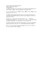
Validity and suitability of the hyperelastic models depend upon application
specifics and the availability of experimental data. Figure 5 provides a glimpse at
comparison of Mooney-Rivilin, Arruda-Boyce and Ogden models with experimental data
for a particular test. Based on such studies, suggestions for selecting a hyperelastic model
appear in Table 5.
15
Figure 5 Comparison of hyperelastic models
Experimental data are from Treloar, L.R.G., Stress strain data for vulcanized rubber under various
types of deformation, Transactions of the Faraday Society, vol. 40, pp.59-70 (1944)
Table 5. Applicability of Hyperelastic Models
Material Model Applicable Strain Range
Neo-Hookean
<30%
Mooney Rivlin
30-200%
Polynomial
Function of order N; feasible to model up to 300%
Arruda Boyce
< 300%
Ogden
< 700%
At Release 7.0, the ANSYS Mechanical program allows one to input
experimental data and obtain hyperelastic coefficients via linear and nonlinear regression
analysis. The new capability is valid for all supported hyperelastic models, and future
releases may extend support to viscoelasticity and creep analysis. When the experimental
data is available in a text file, one can attempt the curve fit for several hyperelastic
models. ANSYS Mechanical provides an error norm and compares experimental data to
calculated coefficients graphically. Figure 6 illustrates the new feature.
λ
λλ
λ
0 2 4 6 8
N
o
m
in
al
st
re
s
0
2
4
6
Mooney-
Arruda-
Ogd
Experim
Uniaxial
N
o
mi
na
l
st
re
ss
[M
Mooney-
Arruda-
Ogd
Experim
λ
λλ
λ
0 2 4 6 8
0
2
4
6
8
1
Biaxial