Hướng Dẫn Xây Dựng Một Căn Nhà Từ Móng Đến Mái FULL A đến Z
Bạn đang xem bản rút gọn của tài liệu. Xem và tải ngay bản đầy đủ của tài liệu tại đây (32.01 MB, 530 trang )
The
Complete
Visual Guide to
Building
a House
John Carroll and Chuck Lockhart
The
Complete
Visual Guide to
Building
a House
The
Complete
Visual Guide to
Building
a House
John Carroll and Chuck Lockhart
C
Text © 2013 by The Taunton Press, Inc.
Illustrations © 2013 by The Taunton Press, Inc.
All rights reserved.
Pp
The Taunton Press, Inc., 63 South Main Street, PO Box 5506, Newtown, CT 06470-5506
e-mail:
Editors: Peter Chapman, Scott Gibson
Copy editor: D iane sinits ky
Indexer: j im c u rtis
Jacket/Cover design: jean-marc Trodaec
Interior design : carol singer | notice design
Layout: Cathy Cassidy, chuck lockhart
Illustrator: chuck lockhart
The following names/manufacturers appearing in The Complete Visual Guide to Building a House
are trademarks: Backer-On™; C. H. Hanson® Pivot Square™; CavClear® ; Cor-A-Vent® ; Dap® Presto Patch® ; DeckArmor™; Delta® -MS; DensShield® ; DrainWrap™; DuPont StraightFlash™; DuPont™ FlexWrap™; Durock® ; Festool® ;
FoamSealR™; HardieBacker® ; Home Slicker® ; Ice & Water Shield® ; Jambsill Guard® ; Level-Best® ; McFeely’s® ;
MortarNet® ; Osmose® ; Porter-Cable® ; RainDrop® ; RockRipper® ; Roofer’s Select™; Schluter® -DITRA; Sheetrock® ;
Shingle Mate® ; Simpson Strong-Tie® ; Stanley® Quick Square® ; StormGuard® ; Super ThoroSeal® ; Sure-Tite™;
SureCorner™; SureSill™ HeadFlash™ and HeadFlash-Flex™; Swanson® Big 12® Speed® Square; T-JAK® ; Tapcon® ;
Telpro® Panellift® ; Timberline® ; Titanium® 30; Typar® ; Tyvek® StuccoWrap® ; Warm-N-Dri® ; Warner® Tool;
WaterWay™; Weathermate™ Sill Pan; WeatherTrek® ; WinterGuard™; Wolman™; WonderBoard®
Library of Congress Cataloging-in-Publication Data
Carroll, John (John Michael), 1949The complete visual guide to building a house / John Carroll and Chuck Lockhart.
pages cm
Includes index.
E-Book ISBN 978-1-62710-608-5
1. House construction--Handbooks, manuals, etc. 2. House construction--Pictorial works. I. Lockhart, Chuck. II. Title.
TH4813.C37 2014
690’.837--dc23
2013048589
Printed in the United States of America
10 9 8 7 6 5 4 3 2 1
A bo u t Yo u r S afet y: C o ns t r u c t i o n i s i n h e re nt l y d a n g e ro u s . Us i n g h a n d o r p owe r t o o l s i m p ro p e r l y o r
i g n o r i n g s afet y p r a c t i c e s c a n l e a d t o p e r m a n e nt i nj u r y o r e ve n d e at h . D o n’ t t r y t o p e r fo r m o p e r at i o ns
yo u l e a r n a b o u t h e re ( o r e l s ew h e re ) u n l e s s yo u ’re c e r t a i n t h ey a re s afe fo r yo u . I f s o m et h i n g a b o u t a n
o p e r at i o n d o e s n’ t fe e l r i g ht , d o n’ t d o i t . L o o k fo r a n ot h e r way. We wa nt yo u t o e nj oy wo r k i n g o n yo u r
h o m e , s o p l e a s e ke e p s afet y fo re m o s t i n yo u r m i n d .
For my mother, Emily J. Carroll (1923–2012)
ACKNOWLEDGMENTS
The idea for this book came from Steve Culpepper, who, at the
time, served as executive book editor for The Taunton Press. In looking at the
available general guides to residential building, Steve found that most were
several decades old and contained outdated information. He felt there was a
need for a reference that reflected today’s building industry, and, to my good
fortune, he thought I should be the one to write it.
Shortly after I started writing this book, however, Steve left Taunton and
Peter Chapman took over as book editor. In addition to all his other duties,
Peter served as the primary editor of this book. Peter’s help proved to be
invaluable. I am especially grateful for his forbearance with me as a writer
whose “cup runneth over” on a regular basis. In chapter after chapter, I submitted too many words and too much information, so Peter would patiently
work with me to pare the text down to a manageable size. With Peter’s help, I
was able to identify the essential information and present it in a much more
concise manner. His insights and suggestions made this book shorter, clearer,
and better organized.
My in-depth discussion of common building procedures would be confusing without accompanying drawings. To graphically represent what I’ve
described, The Taunton Press brought in one of the finest illustrators in the
business, Chuck Lockhart. Having worked as art director for Fine Homebuilding
magazine for 18 years, Chuck brought a wealth of experience to this project.
His drawings are more extensive and provide more detail than would have
been possible with photographs, which require access to building projects at
key moments in the job. Anything I could describe Chuck could draw. Chuck
was able to highlight key details through the use of color and shading; in
many drawings, Chuck skillfully employed such devices as cutaway views and
cross-sectional drawings to show how the details of the job fit into the whole.
After all the parts of this book were produced, the unenviable task of
putting them together fell to Scott Gibson. A skilled carpenter and an accomplished writer and editor, Scott went through every word of text and every
drawing. In addition to looking for and finding mistakes, inconsistencies, and
omissions, Scott extracted information from the running text and applied it,
in the form of labels, to the drawings. His painstaking attention to detail,
his focus on accuracy, and his knowledge of current building practices—
especially the latest in building science—were extremely helpful and greatly
improved the quality of this book.
—John Carroll
table of contents
introduction
pa rt o n e
Building the Structure
Chapter 1
4
Building Foundations6
Chapter 2
Framing Floors, Walls, and Ceilings
50
Chapter 3
Framing Roofs 1: Raftered Roofs
98
Chapter 4
Framing Roofs 2: Trusses, Eaves, Rakes,
and Sheathing142
p a r t tw o
Closing the House to the Weather
182
Chapter 5
Roofing the House184
Chapter 6
Installing Windows, Exterior Doors,
Siding, and Trim
231
Chapter 7
Controlling Moisture in the Ground
and in the Air278
p a r t t h r ee
Finishing the House
Chapter 8
Installing Wall and Floor Coverings
308
310
Chapter 9
Hanging Doors354
Chapter 10
Installing Trim and Cabinets
396
Chapter 11
Building Stairs442
appendices
Conversions
500
Base-1 Proportions of Standard Roof Pitches
501
Backing Angles for Regular Hips and Valleys
502
Base-1 Proportions of Regular Hips and Valley Pitches
503
Converting X-in-12 Roof Pitch to Degrees of an Angle
504
Converting X-in-16.97 Roof Pitch to Degrees
505
Miter and Bevel Settings for Crown Molding
506
Index
514
introduction
In America, houses are built in areas where several feet of
snow accumulate, where hurricanes can be expected, or where temperatures exceed 100°F. In some areas, all these conditions might occur within
the same year. Within these very different climatic regions, furthermore,
individual building sites pose a wide variety of challenges. The surface of
the land might slope steeply; the soil might contain expansive clay or bedrock; or there might be too much moisture in the ground.
To meet these and other challenges, builders have to adjust the design
of their houses to the climatic and topographical conditions of the area
they live in. In Florida, for example, roof structures must be tied down
with steel straps to keep them from being lifted off the walls during hurricanes. In Maine, on the other hand, roof frames must be beefed up to keep
them from collapsing under the weight of several feet of snow. These measures, which are required by building codes, go a long way toward creating
durable houses.
Beyond simply building houses that last, however, builders need
to create houses that perform. Once viewed as basic shelters from the
extremes of the weather, houses are now seen as climate-controlled
enclaves. Most people expect the environment inside their house to be
comfortable year-round, no matter how brutal the weather is outside.
Accomplishing this goal in the face of ever-increasing energy costs is one of
the biggest challenges confronting builders today. Again, the plan of attack
has to be tailored to the location of the house. A house that keeps a family
warm during the winter on the Northern Plains has to be built much differently than a house that provides relief from the heat and humidity in the
Deep South.
The diverse local requirements of home building coupled with an
ever-expanding choice of building materials, tools, and systems present a
fundamental problem for a book like this one. Because there are so many
approaches and options, it’s difficult to decide what to discuss and how
detailed that discussion should be. As on any major building project, there
have been many hard decisions to make and there have been many interesting and worthwhile topics that I could not include in this book.
2
The first thing I decided to drop was a comparative analysis of different
building systems. There are at least a half-dozen alternatives to the light
wood-framed house in America. However, builders and homeowners continue to vote with their wallets for the wood-framed house, which accounts
for 90% of the houses in the United States and Canada. Rather than devote
a good portion of this book to a discussion of the strengths and weaknesses
of the other systems, I chose to focus on the one system that dominates the
housing market: the wood-framed house.
Along the same lines, I’ve focused on mainstream materials when
describing the rest of the house. In the chapter on foundations, for example,
I concentrated on concrete and masonry, and in the chapter on roofing,
I focused on asphalt shingles because most houses in America are built
with those materials. If you happen to use materials that are outside of the
mainstream, there’s a good chance that the installation techniques presented here will work, with minor adjustments, with the materials you use.
I’ve also focused on common building projects and designs. Throughout
the book, I posed hypothetical building projects and then suggested ways
to build them. In these projects, the rectangle predominated—just as it
does on most residential building sites. In general, I have steered clear of
complex designs, such as octangular buildings and curved staircases—both
because they couldn’t be covered adequately in the space allotted and
because they are rare in American houses.
Sticking with common design elements and mainstream materials has
allowed me to go into considerable detail when describing building techniques. These details are often vital to the quality of the job, and builders
who overlook them or try to force them in as an afterthought usually end
up with substandard work. Throughout this book, therefore, I’ve hammered
home the idea that quality work requires two things: forethought and the
proper sequence of installation. It’s essential to think through the details at
the beginning of the job and then install them at just the right moment.
No book, including this one, can provide every important detail for every
job. What I’ve tried to do here is show how to look at the job, anticipate
problems, and then work in the optimal sequence to fit the parts together
smoothly and correctly. Learn these lessons well and you’ll find it easy to
progress to more complex jobs.
i n t r o d u ct i o n
3
4
PA rt o n e
Buildingthestructure
CHAPTER 1
6
BuildingFoundations
CHAPTER 2
50
FramingFloors,Walls,andCeilings
CHAPTER 3
98
FramingRoofs1:RafteredRoofs
CHAPTER 4
142
FramingRoofs2:Trusses,Eaves,
Rakes,andSheathing
5
CHAPTER
1
Building
foundations
thefoundAtionofAhouse servestwobasic
functions.First,itprotectstherestofthehousefromthe
harmfuleffectsofthesoil.Byholdingtheframeofthe
houseupofftheground,thefoundationkeepsitasafe
distancefromthemoisture,frost,termites,mildew,
rot-producingfungi,andotherorganismsthatlivein
theground.
Second,thefoundationservesasatransitionfrom
theirregularsurfaceofthelandtothelevel,plumb,and
squaresurfacesofthehouse.Beforethefoundation,
thereisnothingbutdirt;afterthefoundation,there
shouldbeasquareandplumbstructurewithaleveltop.
Itisuponthisflatandevensurfacethatthecarpenters
begintheframeofthehouse.
Thischapterdealswiththechallengeofbuildinga
foundationthatisstrongenoughtocarrytheweightof
theentirehouse;toughenoughtoenduredecadesof
directcontactwiththeground;andpreciseenoughto
useasafirstreferenceforbuildingtherestofthehouse.
6
2
1
AssessingandPreparingthesoil
Theloadsthathousesplaceonsoilsare,byengineeringstandards,
relativelylight.Mostbuildingcodes,furthermore,areconservativein
design.Theyrequirewidefootingsthatspreadtheloadofthehouse,
allowingthefootingstoworkinsoilthatisnotideal.Ifyoucarefully
followtheprovisionsofthebuildingcode,thesoilyouencounteron
siteisusuallycapableofsupportingthehouseoradditionthatyou
arebuilding.
However,problemsoilsdoexistandtheyrequiremeasuresthat
gobeyondthegeneralprovisionsinthebuildingcode.Foundations
thatsettleunevenlycreateout-of-levelfloorsanddoorsthatdon’t
In some extreme cases, houses have
been ruined beyond repair by failed
foundations.
openandcloseproperly.
whattolookforinthesoil
Thereareafewthingsyoucandotodetermineifyouneedtobring
inasoilsengineer.Thefirstistolookcarefullyatthesoil.Keepan
eyeonhowthesoilbehavesunderload,especiallyafteritrains.
toPtiP
Thesearecommonsenseobservations.Ifthesoilbecomessoftand
mushyunderfootandtrucksandequipmentfrequentlygetmiredin
it,youmighthaveaproblem.
Excavating for the foundationThemostimportantpersonto
Preparing the Soil
If you encounter problem soil
looktoforadviceisyourbuildinginspector.Buildingofficialsare
usuallyfamiliarwiththeproblemsoilsintheirareasandoftenknow
wheretheyaremostlikelytooccur.Theycansometimesrecognize
and are required to bring in
an engineer, make sure you
understand what the engi-
problemsoilssimplybylookingatthem.
neer recommends and follow
those recommendations to the
letter. If you and the building
inspector find the soil acceptable, you need to follow the
requirements of the building
code in your area.
Most problem soils are classified as
clay or silt or a combination thereof.
The inorganic particles in these soils
are very fine—less than 0.003 in. in
diameter. When combined with water,
clays often become sticky or mushy.
When silts dry, they become fluffy;
they are sometimes called rock flour.
Coarse sand and rocky soils have
excellent load-bearing abilities. If you
encounter these soils, however, you
need to make sure that they are consistent over the length of the footing.
Good, stable soils next to unstable
soils can translate into differential
movement.
f r A M i n g f l o o r s , wA l l s , A n d c e i l i n g s
7
excavation:Anoverview
Ifyou’rebuildingabasement,theexcavationconsistsofanopeninginthegroundwitharoughlylevelbottom.Thisopeninghasto
beafewfeetwiderandlongerthanthehouse.Thecorrectelevation
ofthebottomoftheopeningshouldbedeterminedinadvanceas
outlinedinthesectiononfoundationlayoutonp.11.Astheexcavatorgetsdownclosetothiselevation,youshouldstartchecking
theelevationofthebottomoftheopening.Atthesametime,check
thebottomforlevelness.Thetechniquesformeasuringtheelevationandthelevelnessofthebottomoftheopeningarediscussedin
detailinthesectiononp.11onfoundationlayout.
STEP 1 excavatingforthefoundation
Proposed foundation
Monolithic slab: Simply scrape any
organic matter off the surface. The
bottom should be roughly level.
Crawlspace: Scrape any organic
matter off the surface but leave
the grade roughly the same as you
found it.
Basement excavations: It’s important
not to go too deep when you dig
these foundations.
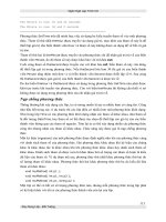
STEP 2 diggingthefootings
1 Building codes require that the bottom of the footing
be below the frost line. Wet soil that freezes expands as
much as 8%. As it expands, it rises and lifts whatever is on
it, including the footings of houses. To avoid frost heave,
as it’s called, you are required to place the footing below
the frost line (the depth to which the ground freezes).
This means that in Maine it’s often necessary to dig down
48 in. or more, while in Florida a trench 8 in. deep is often
sufficient for the footing.
8
B u i l d i n g t h e s t r u c t u r e
The frost line in Maine is 48 in.
The frost line in Florida is 8 in.
1
2 It’s important to make sure that no sizeable amounts of organic matter
remain in the soil after the excavation. Make sure that the footing rests on
well-compacted soil. The simplest and surest way to do this is to place the concrete on undisturbed soil. Digging into undisturbed soil loosens it and fluffs it
up by as much as 50%. If this disturbed soil is left loose under the footing, the
weight of the house eventually compresses it back to its original size. When it
does, the footing often cracks.
Undisturbed soil
Disturbed soil
Remove any
organic matter that
extends below the
proposed excavation.
wAy s o f wo r k i n g
Testing the Soil
One unscientific way to test the load-bearing capacity of
the soil is to push a steel stake into the ground. Building
inspectors often have a T-shaped tool made out of
½-in.-dia. steel rod. To test the soil prior to a footing
Steel stake
pour, the inspector leans on the cross of the T and sees
how far the upright sinks into the ground. If the steel
rod slides into the soil with little resistance, the inspector
Penetrometer
will require remedial work.
A more objective way to test the soil under the footing is with a penetrometer. A penetrometer is a handheld
device that works like a fisherman’s scale in reverse. You
push the penetrometer in the soil and check the pressure
on a calibrated scale. Look for consistent readings along
the length of the footing and a bearing value that meets
the design load in your area (usually 1,500 lb. to 2,500 lb.
per square foot). For soil found to be below that bearing
capacity, most jurisdictions require a plan drawn up by
an engineer.
B u i l d i n g f o u n dAt i o n s
9
3 To avoid the problems caused by disturbed soil in the
4 Use a jumping jack compactor to reconsolidate the soil,
footing, clean loose material out of the footing trench
especially in those spots where tree stumps or large rocks
with hand tools (square shovels, mattocks, and hoes,
have been removed.
for example).
For clay or silt, add
sand or gravel to the
original soil as you
reconsolidate the area.
Dampen the mixture
and place it in 8-in.deep or less layers as
you compact it.
5 Footings spread the load they carry over a broad area. If
the weight of the building is concentrated on the edge of
the footing, however, it can cause the footing to rotate—just
as stepping on the edge of a snowshoe set on top of freshly
fallen snow would cause it to tip over.
Wall centered over footing
10
B u i l d i n g t h e s t r u c t u r e
Off-center wall
An off-center footing
placed on soils with
relatively low bearing
capacity (clay, silt) can
fail.
1
layingoutfoundations
Thegeneralpatternforfoundationlayoutisfromthetopdown.
Theprocessbeginsontheground,wheretherearenostraightlines,
nolevelsurfaces,andnosquarecorners.It’suptoyoutocreatethese
referencesfromscratch.Thefirststepinthisprocessistosetupa
levelinginstrumenttoprojectalevelplaneabovetheground.From
thislevelplane,youestablishtheelevationofthetopofthefoundation.Allsubsequentelevationsarethenmeasureddownfromthis
top-of-foundationelevation.
Leveling instrument
Top of foundation
Atthetop-of-foundationelevation,youcaninstallseveralbatter
boardsthatholdstringswithinalevelplaneatthatheight.Youcan
thenusethestringstopreciselylayoutthepositionsofthefootings
andfoundationwallsinplanview.Onsomefoundations,however,
it’seasiertoexcavatetheopeningforthehouse,thendropdownto
toPtiP
It’s Essential Not to
Overexcavate
thetop-of-footingelevation.Atthatelevation,youcanuseacombi-
Digging too deep, then put-
nationofbatterboardsandformstolayouttheprecisepositionsof
ting dirt back in the opening
thefootingsandwalls.
compromises the integrity of
Whether you lay out the footingandwallsatthetop-of-
the soil under the footings. To
avoid overexcavating, check
foundationelevationoratthetop-of-footinglevel,thelayoutis
the bottom of the opening
suspendedabovetheground.Ithastobethiswayfortworeasons.
with increasing frequency as
First,thesuspendedlayoutestablishestheexactelevationsofthe
you get closer to the desired
keycomponentsofthefoundation.Second,theflat,levelplane
ensuresthatthekeypartsofthefoundationaretherightsizeandin
elevation.
therightplace.Youcan’texecuteapreciselayoutontheground;the
slopedandunevensurfacewilldistortthedimensionsandrender
theminexact.
Thefollowingsectionusestwoexamplestoshowhowtolayout
twodifferentkindsoffoundations.Thedesignspresentedhereare
common;however,someofthedetailsmightnotbeacceptedwhere
youlive.Checkwithyourlocalbuildingofficialstofindoutwhat’s
neededinyourarea.Althoughspecificexamplesareusedhere,the
basicprocedurescanbeadaptedtojustaboutanyfoundation.
f r A M i n g f l o o r s , wA l l s , A n d c e i l i n g s
11
layingoutaBasementfoundation
Inthisexample,thefoundationisa38-ft.by30-ft.basementthatprojectsabout30in.
abovethehighestpointofthesurroundinggrade.Thecornersofthehousehavebeen
roughlymarkedwithstakesandtheelevationestablishedas30in.aboveoneofthe
stakes.Thefirstthingyouhavetodoisguidetheexcavatorthroughtheexcavation
oftheopeningforthefoundation.Inthisphaseofthelayout,makesuretheexcavator
digsintherightplace,getstheopeningthecorrectsize,andmakesthebottomlevel
andatthecorrectheight.Itisupontheroughlylevelsurfaceatthebottomofthe
excavationthatyou’lllayoutthefootingandthefoundationwalls.
Corner stake
Approximately 30 ft.
Approximately 38 ft.
wAy s o f wo r k i n g
Getting the Grade Right
For the final grade around a house, most building codes
require that at least 8 in. of the foundation extend out
of the ground and that the soil slope away from the
Top of
foundation
10 ft.
foundation a minimum of 6 in. within the first 10 ft. To
achieve this minimum standard on the uphill side of the
foundation, measure the elevation 10 ft. uphill from the
planned foundation wall and set the elevation of the top
of the foundation at least 14 in. higher than the elevation at that point. Later, when you backfill around the
foundation, you’ll have enough elevation to form the
required grade on the uphill side. Leaving the founda-
8 in. (min.)
6-in. (min.) slope
14 in. (min.)
tion higher than this minimum standard allows you to
increase the grade and hold the house up even higher
out of the ground.
12
B u i l d i n g t h e s t r u c t u r e
1
STEP 1 recordthepreliminarylayout
1 When the excavator digs the oversized opening for the basement, the stakes
marking the corners of the house will be obliterated. To preserve the layout,
set up a line that extends over the corners of the house, then drive offset
stakes into the ground along that line. Place the offset stakes a set distance
away from the original corner stakes. A 10-ft. offset is common because it’s a
safe distance away from the excavation and it’s an easy distance to remember.
The offset stakes should be in line with the long walls (the 38-ft. walls, in
this example).
Place the offset stakes 10 ft. from
the original corner stakes. Drive
offset stakes deep into the ground
so that very little extends above
the surface.
Flag the location of the
offset stakes with nearby
stakes that extend 16 in.
aboveground; attach
brightly colored ribbons.
Approximately 30 ft.
Original corner stakes
Approximately 38 ft.
2 Record the elevation of the foundation. In this case, the desired elevation
for the top of the foundation is 30 in. above the highest corner stake. Using a
leveling instrument, measure the difference in elevation between the top of
the corner stake and the top of the nearest offset stake. (See “Using a Leveling
Instrument” on p. 14.)
In this example, the bench mark stake
is 6 in. higher than the corner stake.
The top of the foundation is
30 in. above the corner stake.
The top of the foundation, therefore, should be
24 in. above the top of the bench mark stake.
Bench mark
Corner stake
f r A M i n g f l o o r s , wA l l s , A n d c e i l i n g s
13
Using a Leveling Instrument
There are two basic kinds of leveling instruments commonly used by builders:
optical levels (also called sight or telescopic levels) and laser levels. Both of
these kinds of levels come in many forms and are capable of doing numerous
measuring tasks. They share one feature in common, however; they all project
a level line and a level plane. For most residential builders, this basic feature is
the most important role of these tools.
• ESTABLISHING
A LEVEL PLANE
Different leveling instruments project a level plane in
different ways.
An optical tool provides a level line of
sight. Swiveling the tool horizontally
establishes a level plane.
A laser level that projects a single
level line works the same way as
an optical level; swiveling it
establishes a level plane.
Lasers can also project a
level plane that radiates
in all directions from the
instrument.
Many self-adjusting lasers
have flat bottoms and can
be set on any reasonably
flat surface.
Most leveling instruments
can be mounted on a tripod.
• MEASURING
TO THE LEVEL PLANE
You can measure the grade of the land, establish the
elevation of key foundation components, set forms precisely level, and do many other layout tasks by measuring
to the level plane projected by a leveling instrument.
A sighting rod, a large measuring stick
that’s marked off in feet and inches, is
used to determine the measurement.
A tape measure, carpenter’s rule, large
measuring stick, or simply a strip of wood
can serve the same purpose.
House stake
To find the high corner of the grade after a house
has been staked out, measure the distance from the
ground up to the plane at all the corners. The shortest
distance indicates the highest point of the grade.
14
B u i l d i n g t h e s t r u c t u r e
1
• FINDING AND USING THE “DIFFERENCE IN
ELEVATION”
Key elevations are often established in relation to a single reference called a bench mark. Once you know this dimension, you can
quickly compute the other critical elevations.
The distance from the bench mark to the top
of the foundation is the difference of elevation
between the two points.
Bench mark
Proposed top of foundation
• RESETTING
THE LEVEL
The difference in elevation between the bench mark and any
critical elevation of the foundation is constant. The elevation
of the plane projected by the instrument, however, changes
when the instrument is repositioned.
DAY 1: Difference
between site line and top
of proposed foundation
DAY 1: Difference between top of
proposed foundation and bench mark
DAY 2: Difference between
site line and top of proposed
foundation changes.
DAY 2: Difference between top of proposed
foundation and bench mark remains the same.
frAMingfloors
B ,uwA
i l dli l
nsg, f
Ao
nu
dn
cdAt
e i li o
nn
gs
15
STEP 2 Markanddigtheopening
1 Stretch strings between the corner
Flag
stakes and mark the ground about
Offset stake
4 ft. outside of the strings. You
can use a 4-ft. level as a gauge to
measure the distance from the
Use a 4-ft. level to
gauge distance.
Corner stake
string. To mark the line, use lime or
dry masonry mortar poured from a
paper cup or use brightly colored
spray paint.
A dry mortar line or
spray paint marks the
area to dig.
2 Before you begin digging, establish the exact distance that you need to dig
below the bench mark. This requires that you know the design of the foundation, including the exact heights of the materials that you’re going to use.
Make all measurements from the same reference: the targeted top-offoundation elevation. In this example, the top of foundation elevation has
been established at 24 in. above the bench mark.
The top of the walls will be
96 in. above the top of the
footing.
You know that the
bench mark is 24 in.
below the planned
top of the foundation;
therefore, the bottom
of the excavation
should be 76 in.
(100 – 24 = 76) below
the bench mark.
100 in. (96 in. + 4 in. above
the bottom of the excavation)
The bench mark is 24 in.
below the planned top of the
foundation.
76 in. (100 – 24 = 76)
below the bench mark
96 in.
72 in.
4 in.
16
B u i l d i n g t h e s t r u c t u r e
2
1
3 Set up a leveling instrument outside of the opening. After leveling
the instrument, measure the height that it reads above the bench mark
(here, 14 in.). Add this amount to 76 in. The total, 90 in., is the distance from
the level line projected by the instrument to the bottom of the excavation.
Use a surveyor’s rod
to check the depth of
the opening.
14 in.
76 in.
86 in.
Grade stake
90 in.
Place a grade stake as a reference for the top of the footings. Drive this
down until the top is exactly 86 in. below the level line projected by the
leveling instrument. As the drawing on the facing page shows, this is 72 in.
below the bench mark and 96 in. below the desired top-of-foundation.
STEP 3 layoutthefirstwall
EXAMPLE 1 assumes that you removed the instrument at the end of the
excavation and have returned the next day to lay out the footings.
1
Pull a string from one offset
stake to the other along either
of the long walls.
2
Near each side of the excavation, drive in a pair of stakes,
with the string above roughly centered between them. Leave
about 8 in. of the stakes above the bottom of the excavation.
Bench mark
Measuring stick
Offset stake
4
3
Set up the instrument in the bottom of the
opening and shoot the difference in elevation
between the line projected by the instrument
and the top of the grade stake.
Use the instrument and
a measuring stick or rod to
mark the four stakes at the
same distance below the
projected line.
f r A M i n g f l o o r s , wA l l s , A n d c e i l i n g s
17
EXAMPLE 2 assumes that you did not set a grade stake
just after the excavation.
1
Set up the instrument
outside the opening and
shoot a level line anywhere
above the bench mark.
2
The difference in elevation between the bench mark
and the line projected by the instrument is 11 in.
83 in.
Measuring stick
Bench
mark
Offset
stake
3
The top of the footing has to be 72 in.
below the bench mark. Mark the stakes at
83 in. (72 + 11 = 83 ) below the line projected
by the instrument.
4
Once you have the four stakes marked,
attach a horizontal batter board between
each pair of stakes, with the tops of the
boards even with the marks.
The batter board should be level,
exactly 72 in. below the bench
mark, and cross directly below the
string that represents the wall.
5
Transfer the exact location of the
string down to the batter boards.
String
attached to
bench mark
Set a self-leveling
laser with a
plumb beam on
the batter board
and slide it until
the beam strikes
the string.
Use screws rather than
nails to avoid jostling the
stakes out of position.
You also could use a 6-ft.
spirit level or a plumb bob to
transfer this location.
18
B u i l d i n g t h e s t r u c t u r e
6
After marking both batter
boards, set a string from one
mark to the other. The string is
set at the desired elevation for
the top of the footing.
In plan view,
the string is
even with the
outside of the
foundation wall.
Location of
foundation wall