Tài liệu Các mạng UTMS và công nghệ truy cập vô tuyến P8 pdf
Bạn đang xem bản rút gọn của tài liệu. Xem và tải ngay bản đầy đủ của tài liệu tại đây (388.83 KB, 15 trang )
The UMTS Network and Radio Access Technology: Air Interface Techniques for Future Mobile Systems
Jonathan P. Castro
Copyright © 2001 John Wiley & Sons Ltd
Print ISBN 0-471-81375-3 Online ISBN 0-470-84172-9
R
ESOURCE AND
N
ETWORK
M
ANAGEMENT
8.1 I
NTRODUCTION
Operating a 3G network involves managing resources and Network Elements (NE).
This chapter covers these two aspects to complete the deployment issues started in
Chapter 7. Resources here refer primarily to the radio resources and NE refers to the 3G
building blocks, i.e. elements in the CS, PS and radio access networks.
8.2 R
ADIO
R
ESOURCE
M
ANAGEMENT AND
S
IGNALLING
Power control constitutes one of the major tasks of Radio Resource Management
(RRM). Other tasks such as admission control, load control and packet scheduling also
correspond to RRM; however, we will not emphasize them in this section. Power con-
trol aims to minimize interference levels in order to maintain an expected transmission
quality in the air-interface. The UTRA FDD mode depends on soft blocking to effi-
ciently manage multi-rate services. This takes place according to appropriate RRM al-
gorithms covered in Chapter 4.
8.2.1 Managing Power
Power control becomes more critical in the FDD than in the TDD mode. Thus, this sec-
tion concentrates primarily on managing power in WCDMA. The impacts on handover
are also presented.
In WCDMA all users share the same RF band separated by spreading codes. As a result,
each user appears as a random noise to other users. Non-controlled individual power
can therefore interfere unnecessarily with those sharing the same frequency band. To
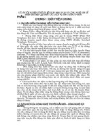
illustrate the need for power control Figure 8.1 shows two MSs in the UL. MS
1
gets
closer to the BS than MS
1
, now if there was no power control both MSs would transmit
at their fixed power P
T
. But since MS
1
is closer, it would have higher power than that of
MS
2
if we assume that the distance of the latter is three times greater than that of MS
1
.
Thus, if the required SNR (S/N
required
) is (1/3), then S/N
1
= 3 and S/N
2
= 1. Thus, MS
2
will suffer the classical near-far effect and may not satisfy the quality of service re-
quired in the link. Furthermore, any 3rd MS coming into the cell will not get the its re-
quired S/N either, and may even cause MS
2
to drop its S/N even lower. Power control
will thus aim to overcome near-far effects and thereby increase capacity with acceptable
link quality.
302 The UMTS Network and Radio Access Technology
06
06
3
G
3
G
3
7
3
7
%6
Figure 8.1 Power control to prevent near-far effect.
8.2.1.1 Fast Power Control (FPC)
The FDD mode uses fast power control with 1.5 kHz frequency (i.e. 1500 times/s) in
both UL and DL. It operates at a faster rate than any path loss change. The FPC uses the
closed-loop option as noted in Chapter 4. We see higher gains of FPC in low mobile
speeds than for high mobile speeds, and in received powers than in transmitted powers.
At speeds above 50 km/h, e.g. FPC does not contribute much due to the higher multi-
path gains. We can find more information about fast power control in [1].
Other gains of FPC depend on diversity, e.g. multi-path diversity, receive, transmit antenna
diversity, and macro-diversity. Less diversity implies more variations in the transmitted
power. Thus, we get smaller power rise
1
in the presence of more multi-path diversity.
In DL macrocell coverage with WCDMA, power rise gets critical because it directly
intervenes in the required transmission power, which determines the transmitted inter-
ference. Hence, to maximize the DL capacity, we should select the quantity of diversity,
such that it minimizes the transmission power required by a link, since the received
power level does not affect the capacity in the DL.
In the UL, the level of transmission power from the different MSs does have direct impact
on the interference to the adjacent cells, and the received power determines the level of
interference to other users in the same cell. Diversity in this case does not have much im-
pact, which means that UL capacity of a cell would be maximized by minimizing the re-
quired received powers, and the amount of diversity would not affect the UL capacity.
When MSs move at high velocities, the FPC does not follow fast fading; we would re-
quire higher received power level to obtain the expected quality. Thus, in this scenario
diversity does help to maintain the received power level constant, thereby allowing a
lower average received power level to provide the required quality of service.
8.2.1.2 Power Control in Handover (HO)
Before we discuss power control in HO, we briefly review the HO types. The two types
of HO in our FDD mode include Softer and Soft HO.
_______
1
If we define power rise as the relative average transmission power in a fading channel compared to the non-
fading, while the received power level is the same both in fading and in non-fading channels with ideal
power control.
Resource and Network Management 303
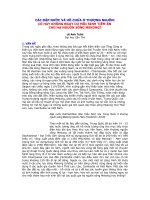
8.2.1.2.1 Softer Handover
As illustrated in Figure 8.2 softer HO occurs when a MS passes through the overlapping
coverage of two adjacent sectors of a BS. Communications between the BS and MS
take place concurrently through two channels (i.e. one to each sector or cell). The con-
current links use 2 separate DL codes so the signals are perceived by the rake receiver
and processed as in multi-path reception, but with the rake fingers generating the corre-
sponding code for each sector.
SI8
HT
UurÃHTÃtrÃhr
vthyÃsÃiuÃrp
TrpÃ6
7T
TrpÃ7
Figure 8.2 Softer handover event.
A similar process occurs in the UL, each BS sector receives the MS code, which gets
routed to the same rake receiver for maximal ratio combining. In softer HO we have
only one power control loop active per connection.
Softer HO events do not exceed 16% of established links, and in the UL we do not use
additional resources except for the extra rake fingers. Neither does the BS need to pro-
vide additional DL transmission power to complete the softer HO process.
8.2.1.2.2 Soft Handover
In soft handover, a MS passes through the overlapping cell coverage area of two sec-
tors, which correspond to different BSs, e.g. BS-a and BS-b as illustrated in Figure 8.3.
Communications between the MS and BS occurs concurrently through two different
channels, i.e. one from each BS. The MS receives both signals by maximal ratio com-
bining Rake processing.
While in the DL softer and soft HO behave basically in the same way
2
and the MS does
not see any difference between them; in the UL soft HO behaves differently. For exam-
ple, the MS receives the code channel from both BSs. This information then gets routed
to the RNC for macro-diversity combining thereby to obtain the same frame reliability
indicator provided for outer loop PC, i.e. to select the best frame after each interleaving
period within 10–80 ms.
_______
2
Thus, soft and softer HO can also take place in combination with each other.
304 The UMTS Network and Radio Access Technology
51&
06
UurÃHTÃtrÃurÃhr
vthyÃsÃiuÃ7TÃi
vuÃqvssrrÃQ8Ãpq
%6D
%6E
Figure 8.3 Soft handover event.
In general, soft HO will not exceed 40% of the links. However, it will not go below
20% either. Thus, we cannot neglect soft HO overhead when dimensioning. For exam-
ple, we must allocate: extra transmission power in the BS, extra BS rake receiver chan-
nels and extra rake fingers in the MS, and extra transmission links between the BSs and
the RNCs.
An appropriate provision and/or an efficient FPC management in WCDMA will maintain
most of its total capacity
3
during HO. In FPC we need to deal effectively with the BS
power drifting and the accurate detection of UL power control commands from the MS.
Inaccurate reception of power control commands in the BS due to propagation impacts,
such as delay or shadowing will trigger undesired power events from the BSs, e.g. in-
creasing power when expecting power decrease. This power drifting will degrade soft
HO. On the other hand, the RNC can control such drifting by limiting the power control
dynamics or by obtaining DL reference transmission power levels from the BSs. Then
send this reference value for the DL transmission powers to the BSs.
In the UL all BSs send independent power control commands to the MS to control its
transmission power. The MS can then decrease its power if one BS demands so, and
apply maximal ratio combining to the data bits in soft HO since the same data is sent
from all soft HO BSs.
8.2.1.3 Outer Loop Power Control
We use outer loop power control to keep the quality of the FPC communication at the
required level. An excessive high FPC quality will waste capacity. Outer loop power
control applies to both UL and DL, since FPC also applies to both
4
. While FPC has a
frequency of 1.5 kHz, the outer loop power control has a frequency range of 10–100 Hz.
_______
3
Otherwise up to 40% of the total capacity can decrease.
4
In IS-95 outer loop power control applies only to the UL because there is no fast power control in DL.
Resource and Network Management 305
8.2.1.4 Conclusions
In the preceding sections, we have highlighted power control and handover aspects pri-
marily to indicate their importance when planning for capacity and coverage. Other
source such as [2–6,15,16] cover more in depth power control issues.
Other related areas of radio resources for the FDD mode, e.g. admission control are
found in [7–10]. Sources that apply to the resource management of the TDD mode, are
found in [11–14].
8.3 N
ETWORK
M
ANAGEMENT
8.3.1 Introduction
Forthcoming 3G systems such as UMTS will serve as multi-technology platforms
5
for
new and innovative services. These services will appear within a highly competitive
market demanding uniqueness at the best price. To meet the demands, it will be impera-
tive to maintain efficient operational costs through an appropriate NE management sys-
tem. We will obtain the ideal NMS only through the right combination of NE element
control techniques. On the other hand, because of the wide spread 2G networks evolv-
ing into 3G, managing UMTS NE will not be the only challenge. We also need inte-
grated 2G/3G systems.
8.3.2 Network Management Characteristics
Considering the items on the preceding section, a NMS will have at least the following
characteristics:
Capabilities to integrate and manage 2G NE besides 3G building blocks.
Support advanced functions and techniques to cope with the multifarious UMTS
technology, and maintain diverse service functionality, as well as quality of service
provision.
Have an inherent easy to use man–machine interface to minimize personnel train-
ing requirements.
Support a multiple set of protocols and open interfaces to interact with multi-
vendor equipment.
In the context of GSM as a 2G system, a basic set of capabilities will include network
management applications in combination with technology specific features to appropri-
ately deploy and operate all components of a complex GSM/GPRS/UMTS network.
8.3.3 A Generic Functional View of a 3G NMS System
Figure 8.4 illustrates a reference architecture of an integrated NMS system capable of
managing a combined 2G/3G network. A layered approach allows us to address the
complex hybrid system to monitor, i.e. GSM and UMTS NEs and performance.
_______
5
For example, IP, ATM; WCDMA, etc.
306 The UMTS Network and Radio Access Technology
At the network management level the essential functions would include:
Fault control – control and monitor the function and performance of allocated net-
work resources
Ticketing and reporting – trouble reporting and service assignment to the opera-
tions team
Set up and configuration – assist in complex system parameter configuration
Resource management – data and inventory tracking to provide visibility of avail-
able physical resources in the network.
I@UXPSFÃ@G@H@IUÃG6`@S
DrshprÃQyhr
DrthvÃQyhr
I@UXPSFÃH6I6B@H@IUÃG6`@S)
AhyÃpy
UvpxrvtÃhqÃrvt
rÃhqÃpsvthv
rprÃhhtrr
DrthvÃGvx
BHTBQST
VHUT)
ÃShqvÃ6ppr
±ÃQhpxrÃTvpu
±Ã8vpvÃTvpu
UhÃTr)
Ã7hpxirÃT9CÃt
ÃHXÃyvxÃt
±Ã6UHDQÃyhrÃt
HyvWrqÃ@
ÃG6IDQÃI@)
ÃW6TÃryrr
±ÃAhyÃrÃI@
±ÃHvvtÃI@
T@SWD8@ÃH6I6B@H@IUÃG6`@S
TV7I@UXPSFÃH6I6B@H@IUÃG6`@S
Drthrq
8yÃ8rr
Figure 8.4 A layered NMS architecture reference.
At the sub-network management layer, the integrated architecture will aim to gather
different sub-domains into one domain. This blending of different control technologies
will provide a unified management process. The result will afford a consolidated view
of alarm surveillance; performance and configuration access to all related nodes of the
integrated domain. The sub-domains include but are not limited to:
GMS/GPRS and UMTS Sub-domains – incorporating radio access, packet and cir-
cuit switching network elements.
The Transport system – has to do primarily with the core transport network incor-
porating, e.g. a SDH backbone, a set of microwave links, and overlay ATM/IP
network running on the SDH ring.
The multi-vendor environment set up stands to support NE from different vendors,
which will continue as part of a common element to 2G/3G or evolve through up-
grade from 2G to 3G. The setup may incorporate LAN or IP, VAS, and fault report
or monitoring NEs.