Thiết kế và lập trình hệ thống - Chương12
Bạn đang xem bản rút gọn của tài liệu. Xem và tải ngay bản đầy đủ của tài liệu tại đây (309.53 KB, 16 trang )
Systems Design and Programming Basic I/O IV CMPE 310
1 (April 17, 2002)
UMBC
U M B C
U
N
I
V
E
R
S
I
T
Y
O
F
M
A
R
Y
L
A
N
D
B
A
L
T
I
M
O
R
E
C
O
U
N
T
Y
1
9
6
6
Programmable Communications Interface: 16550
A universal asynchronous receiver/transmitter (UART).
Operation speed: 0-1.5M Baud (Baud is # of bits transmitted/sec, including
start, stop, data and parity).
Includes:
• A programmable Baud rate generator.
• Separate FIFO buffers for input and and output data (16 bytes each).
Asychronous serial data:
Transmitted and received without a clock or timing signal.
Two 10-bit frames of asynchronous data.
7- or 8- bit ASCII, e.g. w or w/o parity, is possible.
D
0
S
T
* *
D
1
D
2
D
3
D
4
D
5
D
6
P
*
D
0
S
T
D
1
D
2
D
3
D
4
D
5
D
6
P
* *
start bit
7 data bits
parity stop bit
Systems Design and Programming Basic I/O IV CMPE 310
2 (April 17, 2002)
UMBC
U M B C
U
N
I
V
E
R
S
I
T
Y
O
F
M
A
R
Y
L
A
N
D
B
A
L
T
I
M
O
R
E
C
O
U
N
T
Y
1
9
6
6
Programmable Communications Interface: 16550
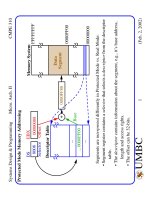
The 16550 can control a modem through
DSR, DTR, CTS, RTS, RI and DCD.
In this context, the modem is called the data set while the 16550 is called the
data terminal.
16550
A
0
BAUDOUT
SIN
SOUT
D
0
D
1
D
7
D
6
D
5
D
4
ADS
D
3
D
2
WR
MR
A
1
A
2
CS
0
CS
1
CS
2
RD
RD
WR
XIN
XOUT
TXRDY
RXRDY
DDIS
INTR
RCLK
RTS
CTS
DTR
DSR
DCD
RI
OUT
1
OUT
2
Two separate sections are
responsible for data communications:
Receiver
Transmitter
Can function in:
simplex: transmit only
half-duplex: transmit and
full-duplex: transmit and
receive but not simultaneously
receive simultaneously
Systems Design and Programming Basic I/O IV CMPE 310
3 (April 17, 2002)
UMBC
U M B C
U
N
I
V
E
R
S
I
T
Y
O
F
M
A
R
Y
L
A
N
D
B
A
L
T
I
M
O
R
E
C
O
U
N
T
Y
1
9
6
6
Pinout of the 16550
A
0
, A
1
and A
2
: Select an internal register for programming and data trans-
fer.
ADS: Address strobe used to latch address and chip select. Not needed on
Intel systems -- connected to ground.
BAUDOUT: Clock signal from Baud rate generator in transmitter.
CS
0
, CS
1
, CS
2
: Chip selects
CTS: Clear to send -- indicates that the modem or data set is ready to
exchange information. (Used in half-duplex to turn the line around).
A
2
A
1
A
0
Register
0 0 0 Receiver buffer (read) and transmitter holding (write)
0 0 1 Interrupt enable
0 1 0 Interrupt identification (read) and FIFO control (write)
0 1 1 Line control
1 0 0 Modem control
1 0 1 Line status
1 1 0 Modem status
1 1 1 Scratch
Systems Design and Programming Basic I/O IV CMPE 310
4 (April 17, 2002)
UMBC
U M B C
U
N
I
V
E
R
S
I
T
Y
O
F
M
A
R
Y
L
A
N
D
B
A
L
T
I
M
O
R
E
C
O
U
N
T
Y
1
9
6
6
Pinout of the 16550
D
7
-D
0
: The data bus pins are connected to the microprocessor data bus.
DCD: The data carrier detect -- used by the modem to signal the 16550 that
a carrier is present.
DDIS: Disable driver output -- set to 0 to indicate that the microprocessor is
reading data from the UART. Used to change direction of data flow
through a buffer.
DSR: Data set ready is an input to 16550 -- indicates that the modem (data
set) is ready to operate.
DTR: Data terminal ready is an output -- indicates that the data terminal
(16550) is ready to function.
INTR: Interrupt request is an output to the micro -- used to request an inter-
rupt.
Receiver error
Data received
Transmit buffer empty
Systems Design and Programming Basic I/O IV CMPE 310
5 (April 17, 2002)
UMBC
U M B C
U
N
I
V
E
R
S
I
T
Y
O
F
M
A
R
Y
L
A
N
D
B
A
L
T
I
M
O
R
E
C
O
U
N
T
Y
1
9
6
6
Pinout of the 16550
MR: Master reset -- connect to system RESET
OUT1, OUT2: User defined output pins for modem or other device.
RCLK: Receiver clock -- clock input to the receiver section of the UART.
Always 16X the desired receiver Baud rate.
RD, RD: Read inputs (either can be used) -- cause data to be read from the
register given by the address inputs.
RI: Ring indicator input -- set to 0 by modem to indicate telephone is ring-
ing.
RTS: Request-to-send -- signal to modem, indicating UART wishes to send
data.
SIN, SOUT: Serial data pins, in and out.
RXRDY: Receiver ready -- used to transfer received data via DMA tech-
niques.
TXRDY: Transmitter ready -- used to transfer transmitter data via DMA.
WR, WR: Write (either can be used) -- connects to micro write signal to
transfer commands and data to 16550.
XIN, XOUT: Main clock connections -- a crystal oscillator can be used.
Systems Design and Programming Basic I/O IV CMPE 310
6 (April 17, 2002)
UMBC
U M B C
U
N
I
V
E
R
S
I
T
Y
O
F
M
A
R
Y
L
A
N
D
B
A
L
T
I
M
O
R
E
C
O
U
N
T
Y
1
9
6
6
Programming the 16550
Two phases: Initialization, operation.
Initialization:
After RESET, the line control register and baud rate generator need to be
programmed.
Line control register sets the # of data bits, # of stop bits and the parity.
Addressed at location 011.
Stop bits: S = 1, 1.5 stop bits used for 5 data bits, 2 used for 6, 7 or 8.
DL SB ST P PE S L1 L0
Data length:
00 = 5 bits, ... 11 = 8 bits.
Stop bits: 0 = 1, 1 = 1.5/2
Parity enable
Parity type, 0 odd.
Stick bit, 0 = stick parity off
Send break, 0 = off
Enable divisor latch