Thiết kế và lập trình hệ thống - Chương14
Bạn đang xem bản rút gọn của tài liệu. Xem và tải ngay bản đầy đủ của tài liệu tại đây (422.25 KB, 25 trang )
Systems Design & Programming Interrupts I CMPE 310
1 (April 24, 2002)
UMBC
U M B C
U
N
I
V
E
R
S
I
T
Y
O
F
M
A
R
Y
L
A
N
D
B
A
L
T
I
M
O
R
E
C
O
U
N
T
Y
1
9
6
6
Interrupts
Interrupt processing is an alternative to polling.
The Intel microprocessors support hardware interrupts through:
• Two pins that allow interrupt requests, INTR and NMI
• One pin that acknowledges,
INTA, the interrupt requested on INTR.
And software interrupts through instructions:
• INT, INTO, INT 3, BOUND
Control is provided through
• IF and TF flag bits
• IRET and IRETD
Time
Executing task on the Microprocessor
Main program
Keyboard ISR
Printer ISR
Systems Design & Programming Interrupts I CMPE 310
2 (April 24, 2002)
UMBC
U M B C
U
N
I
V
E
R
S
I
T
Y
O
F
M
A
R
Y
L
A
N
D
B
A
L
T
I
M
O
R
E
C
O
U
N
T
Y
1
9
6
6
Interrupt Vector Table
INT and INT3 behave in a similar way.
INT n:
Calls ISR located at vector n (n*4).
The INT instruction requires two bytes of memory, opcode plus n.
BOUND and INTO are both conditional.
BOUND:
AX is compared with DATA and DATA+1, if less than an interrupt
occurs.
AX is compared with DATA+2 and DATA+3, if greater than an inter-
rupt occurs.
INTO:
Checks the overflow flag (OF). If OF=1, the ISR is called.
IRET removes 6 bytes from the stack, 2 for IP, 2 for CS and 2 for FLAGS.
BOUND AX, DATA ;Compares AX with DATA
Systems Design & Programming Interrupts I CMPE 310
3 (April 24, 2002)
UMBC
U M B C
U
N
I
V
E
R
S
I
T
Y
O
F
M
A
R
Y
L
A
N
D
B
A
L
T
I
M
O
R
E
C
O
U
N
T
Y
1
9
6
6
Interrupt Vector Table
Divide error
Single-step
NMI pin
1-byte breakpoint
Overflow (INTO)
Bound
Undefined Opcode
Coprocessor not avail
Double fault
Coproc seg overrun
Invalid task state seg
Segment not present
Stack seg overrun
General protection
Page fault
Unassigned
Coprocessor error
000H
004H
008H
00CH
010H
014H
018H
01CH
020H
024H
028H
02CH
030H
034H
038H
03CH
040H
14-31 Reserved
32-255 User defined
080H
Seg high Seg low
Offset high
Offset low
Byte 3 Byte 2 Byte 1 Byte 0
The interrupt vector table is located in
the first 1024 bytes of memory at
addresses 000000H through 0003FFH.
There are 256 4-byte entries (segment
and offset in real mode).
0
1
2
3
4
5
6
7
8
9
10
11
12
13
14
15
16
Systems Design & Programming Interrupts I CMPE 310
4 (April 24, 2002)
UMBC
U M B C
U
N
I
V
E
R
S
I
T
Y
O
F
M
A
R
Y
L
A
N
D
B
A
L
T
I
M
O
R
E
C
O
U
N
T
Y
1
9
6
6
Real Mode Interrupts
After the execution of each instruction, the microprocessor determines
whether an interrupt is active by checking, in order:
Other instruction executions
Single-step
NMI
Coprocessor segment overrun
INTR
INT
If one or more of these conditions are present, then:
FLAGS is pushed onto the stack
Both the interrupt (IF) and trap (TF) flags ar e cleared, which disables the
INTR pin and the trap or single-step feature.
The CS and IP are pushed onto the stack.
The interrupt vector contents are fetched and loaded into CS and IP and
execution resumes in the ISR.
On IRET, CS, IP and FLAGS are popped.
IF and TF are set to the state prior to the interrupt.
Systems Design & Programming Interrupts I CMPE 310
5 (April 24, 2002)
UMBC
U M B C
U
N
I
V
E
R
S
I
T
Y
O
F
M
A
R
Y
L
A
N
D
B
A
L
T
I
M
O
R
E
C
O
U
N
T
Y
1
9
6
6
Real and Protected Mode Interrupts
The return address (CS/IP) is pushed onto the stack during the interrupt.
The return address can point to:
The next instruction.
The offending (current) instruction.
The latter case occurs for interrupts 0, 5, 6, 7, 8, 10, 11, 12 and 13.
This makes it possible to try the instruction again.
Protected Mode:
The same interrupt assignments are made and the same sequence of opera-
tions occurs in protected mode but the interrupt table is different.
Instead, 256 interrupt descriptors are used in the interrupt descriptor table
(IDT).
Offset (A31-A16)
P
DPL
01110
00H
01234567
Segment Selector
Offset (A15-A0)
Present
Systems Design & Programming Interrupts I CMPE 310
6 (April 24, 2002)
UMBC
U M B C
U
N
I
V
E
R
S
I
T
Y
O
F
M
A
R
Y
L
A
N
D
B
A
L
T
I
M
O
R
E
C
O
U
N
T
Y
1
9
6
6
Hardware Interrupts
The INTR pin must be externally decoded to select a vector.
Any vector is possible, but the interrupt vectors between 20H and FFH
are usually used (Intel reserves vectors between 00H and 1FH).
INTA is an output of the microprocessor to signal the external decoder to
place the interrupt number on data bus connections D7-D0.
The INTR pin is set by an external device (8259A) and cleared in the ISR.
The input is automatically disabled by the microprocessor once it is rec-
ognized and re-enabled by IRET or IRETD instruction.
Timing diagram of the handshake.
INTR
LOCK
INTA
D7-D0
Vector number
Systems Design & Programming Interrupts I CMPE 310
7 (April 24, 2002)
UMBC
U M B C
U
N
I
V
E
R
S
I
T
Y
O
F
M
A
R
Y
L
A
N
D
B
A
L
T
I
M
O
R
E
C
O
U
N
T
Y
1
9
6
6
Hardware Interrupts
Simpliest method of generating an interrupt vector:
D
0
D
1
D
6
D
5
D
4
D
3
D
2
D
7
VCC
INTA
no connection
Low data
bus
27K
Always generates interrupt
vector FFH in response
to INTR.
Systems Design & Programming Interrupts I CMPE 310
8 (April 24, 2002)
UMBC
U M B C
U
N
I
V
E
R
S
I
T
Y
O
F
M
A
R
Y
L
A
N
D
B
A
L
T
I
M
O
R
E
C
O
U
N
T
Y
1
9
6
6
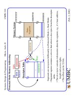
Tri-state Buffer for Generating the Interrupt Vector
D
0
D
1
D
6
D
5
D
4
D
3
D
2
D
7
INTA
Low data
bus
V
CC
74ALS244
Y
1
...
A
1
...
GG
Applies interrupt
vector 80H in
response to
INTA.
Systems Design & Programming Interrupts I CMPE 310
9 (April 24, 2002)
UMBC
U M B C
U
N
I
V
E
R
S
I
T
Y
O
F
M
A
R
Y
L
A
N
D
B
A
L
T
I
M
O
R
E
C
O
U
N
T
Y
1
9
6
6
An Example 82C55 Interrupt Configuration
STB
D
0
D
7
Keyboard
DAV
ASCII
82C55
D
0
D
7
A
0
A
7
B
7
B
0
C
7
C
0
CS
D
7
-- D
0
8
IORC
Wait2
RD
WR
A
0
A
1
Reset
A
0
A
1
Reset
16L8
A
3
A
4
A
5
A
7
A
8
A
6
A
9
A
10
I
1
I
10
O
1
O
8
A
0
IOWC
A
11
A
13
A
14
A
12
A
15
Y
1
...
A
1
...
GG
INTR
INTA
Systems Design & Programming Interrupts I CMPE 310
10 (April 24, 2002)
UMBC
U M B C
U
N
I
V
E
R
S
I
T
Y
O
F
M
A
R
Y
L
A
N
D
B
A
L
T
I
M
O
R
E
C
O
U
N
T
Y
1
9
6
6
Handling more than 1 IRQ
If any of IRQ
x
goes low, the NAND goes low requesting an interrupt.
Note that if more than one IRQ goes low, a unique interrupt vector is gener-
ated and an interrupt priority needs to be defined.
The Interrupt Vector table must be expanded to accommodate this.
D
0
D
1
D
6
D
5
D
4
D
3
D
2
D
7
INTA
V
CC
74ALS244
Y
1
...
A
1
...
GG
INTR
IRQ
0
IRQ
6
6 5 4 3 2 1 0 Vect
IRQs
1 1 1 1 1 1 0 FEH
1 1 1 1 1 0 1 FDH
1 1 1 1 0 1 1 FBH
1 1 1 0 1 1 1 F7H
1 1 0 1 1 1 1 EFH
1 0 1 1 1 1 1 DFH
0 1 1 1 1 1 1 BFH