Tài liệu Pharmaceutical Coating Technology (Part 6) pdf
Bạn đang xem bản rút gọn của tài liệu. Xem và tải ngay bản đầy đủ của tài liệu tại đây (1.09 MB, 21 trang )
Page 152
6
The development of film-coating processes
Graham C.Cole
SUMMARY
To develop a film-coating process requires a laboratory test rig that can be scaled-up to meet production
requirements. All the process parameters need to be optimized. A scheme is discussed here that provides
an integrated computer-controlled system designed for aqueous film coating in a side-vented pan. A
comparison is made of energy requirements of a column-coating system and a coating pan.
All the major operational coating parameters can be measured and recorded under the overall control of
a microcomputer. The monitored values are displayed on a computer screen at selected short intervals,
e.g. 5 s, and, at selected longer intervals, e.g. 1 min, they can be printed as hard copy.
This chapter describes the selection of instruments to measure the appropriate parameters; how the
coating process may be optimized using a laboratory side-vented pan; the loop closed to provide
automatic control, and the process scaled-up to control successfully the coating of production size
batches.
6.1 INTRODUCTION
To set up a suitable experimental rig required for the general development of all coating processes,
instruments are required to measure and record data from the process parameters. First it is necessary to
determine which parameters have a critical effect on the performance of the coating system to produce a
tablet that is pharmaceutically acceptable.
The following process parameters are possibilities:
Page 153
After conducting a number of preliminary experiments, a number of these parameters can be rejected
as they do not critically affect the appearance and quality of the film-coated tablet. This list is then
reduced to ten which, by installing the appropriate instruments, are used to record the raw data. These
instruments are linked through an analogue-to-digital converter to a computer and printer and the values
for each parameter recorded on a specifically numbered channel.
These are designated the critical parameters. Each can easily be scanned, measured and recorded. The
next stage in the set-up of the test rig is the selection of a coating pan, coating accessories, instruments,
computer and printer. An example is a model 10 Accelacota (Manesty Machines Ltd). However, any
suitable manufacturer’s
• Inlet air flow rate.
• Inlet air temperature.
• Inlet air humidity.
• Outlet air flow rate.
• Outlet air temperature.
• Outlet air humidity.
• Leakage air rate to the atmosphere through the casing.
• Spray concentration.
• Spray temperature.
• Spray flow rate.
• Quantity of attrition from cores (by filtration of the exhaust air).
• Quantity of spray not applied to tablets (by filtration of the exhaust air).
• Tablet-bed temperature.
• Power/torque to keep the drum turning.
• Rotational speed of the drum.
• Electrical power consumption of fans.
• Heat input to inlet air.
• Pressure drop, inlet-outlet airstream.
• Atomizing air pressure. (The atomizing air flow can be neglected as a calculation will show that
it is less than 2% of the total air throughput.)
Channel
0 Coating spray rate.
1 Inlet air flow rate.
2 Inlet air temperature.
3 Outlet air flow rate.
4 Outlet air temperature.
5 Outlet air dew-point.
6 Fan rotational speed.
7 Coating drum drive torque.
8 Coating suspension temperature.
9 Tablet surface temperature.
10 Atomising air pressure.
15 10-volt reference source.
Page 154
coating pan could be used, depending on the objectives of the coating development programme.
6.2 DEVELOPMENT OF THE EXPERIMENTAL RIG
The coating pan
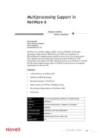
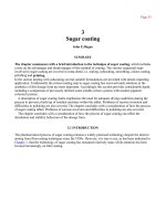
As an example, a model 10 Accelacota could be used. A unit is shown diagrammatically in Fig. 6.1.
The unit has a horizontal rotating cylindrical drum, the curved surface of which is uniformly
perforated. The ends of the cylinder are conically dished, so that tablets in the drum are turned over and
also mixed laterally. There are baffles to assist this stirring action. Hot drying air enters the drum
through the perforations on the side remote from the tumbling tablet bed, and is drawn through the bed
by a fan in the exhaust plenum. This plenum has a mouth that fits closely to the outside of the perforated
curved surface of the drum.
The angles of the front and rear sides of the pan are 56° and 61° respectively, which was originally
intended to ensure complete mixing of the tablets from the top of the bed to the bottom and from front to
rear. However, it was found that this was insufficient to ensure homogeneous mixing and baffles were
fitted. Generally, they are of the same shape but of different size for each model and can be easily
removed or replaced with baffles of different design, depending on the physical
Fig. 6.1 Schematic diagram of Model 10 Accelacota.
Page 155
characteristics of the tablet to be coated, e.g. friability, and the properties that the coat is designed to
impart to the tablet, e.g. enteric coating. In this case the degree of mixing becomes a critical parameter.
A means is required of applying the coating suspension or solution and storing it during application to
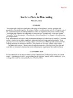
ensure that it remains homogeneous. Most manufacturers supply suitable units. A typical unit designed
for the application of aqueous filmcoating solutions and suspensions is shown in Fig. 6.2
. The controls
are mounted on the top face of the unit and comprise gauges for pump speed, fluid pressure, atomizing
air pressure and on/off switches. Below each gauge is the regulator which controls the circuit to which
the pressure gauge applies. The adjustment is effected by rotating the main control knob of each
regulator while the adjustment is secured by the inner lockscrew. On the panel there are also two valves
controlling the flow and return of coating solution.
The operation of the unit is briefly as follows: Compressed air is supplied to the air inlet manifold and
from there to three different internal supplies. One supply passes through an air-pressure regulator to the
liquid pump and the pressure of this air is shown on the pump air-pressure gauge. This pressure governs
the pressure of the liquid. A second air supply passes through a regulator which controls the atomizing
air-pressure gauge and the air is then supplied direct to the atomizing air connection on the spray bar in
the coating pan. Also connected into this circuit is a
Fig. 6.2 Spray unit control unit.
Page 156
pressure stop valve which controls the signal air to the spray bar. The signal air is used to provide an
option for stopping and starting the spray. In some cases continuous spraying results in overwetting.
The third air supply taken from the air inlet manifold passes through an air-pres-sure regulator which
feeds air to two air-controlled diaphragm type fluid-pressure regulators. Two regulators are necessary to
supply the relatively large volumes of fluid used on the larger models of coating pans. This method of
control has been employed so that there is no differential pressure between the outputs from the two
regulators.
Coating fluid is picked up from the storage container by a peristaltic pump, and pumped at pressure to
the fluid-pressure regulators where the supply pressure is controlled and maintained. This pressure is
shown on the fluid-pressure gauge. The coating solution is then fed through a valve to the coating pan
spray bar, spray nozzle and the excess is returned by means of a second pipe, through a second valve, to
the solution container. In the case of low-viscosity liquids, the return control valve can be used to create
a back pressure in the system to keep the flow rate constant.
The flow is controlled by:
This arrangement is versatile and easy to clean. No metal surfaces of the pumping system are in
contact with the coating suspension during the spray operation, which reduces the risk of cross-
contamination. It is possible to control the speed of the pump by linking it to a signal such as the
temperature of the exhaust air, inlet air or tablet-bed temperature. One way of controlling the process is
to use the exhaust temperature as a controlling parameter as this is an indirect measure of the tablet-bed
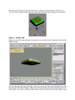
temperature and is sensitive to process changes. By using a minimum exhaust temperature of 35°C and
linking the spray rate directly to this temperature, the pump would automatically stop if the temperature
fell below this level. For each degree rise in temperature above this level the speed of the pump
increased, up to a maximum of 50 rev/min thus increasing the spray rate. This relationship is illustrated
in Fig. 6.3
. The relationship between these three variables is inserted as an instruction in the computer
programme. By altering this instruction different spray rates can be obtained, depending on the size of
the coating pan used and the spray rate required. It can also be demonstrated that a balance can be
achieved between the inlet temperature, exhaust temperature and spray rate during the coating operation.
To do this a simplified programme must be written to provide automatic control of the coating
process. For example:
1. the speed of the pump;
2. the internal diameter of the flexible silicone tube which provides a range of flow rates from
0.002 to over 8 g/s;
3. the nozzle setting.
Channel
0 Inlet drying air temperature °C
1 Outlet drying temperature °C
Page 157
Fig. 6.3 Relationship between pump speed, temperature and spray rate.
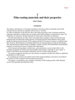
The advantage of a computer-based system means that these parameters can be scanned and measured
rapidly, say every 5 s, and displayed on the VDU. The results can then be recorded every minute, and
every 5 min the spray flow rate can be calculated and recorded. An example of part of the type of a
printout is shown in Fig. 6.4
.
At the completion of the coating process and when a predetermined quantity of coating suspension
has been applied, a ‘batch completed’ sign is flashed onto the VDU, the pump is automatically switched
off and a summary of the processing parameters recorded on the printout.
This process and control programme is schematically represented in Fig. 6.5
.
The spray bar fitted to larger coating pans consists of three chambers, one of which contains the
coating fluid, one the atomizing air, and one the signal air. The spray guns are mounted directly on the
chamber which contains the coating solution and separate pipe connections are made between the gun
and the two air chambers.
2 Pump speed rev/min
3 Coating suspension used
kg×10
−3
4 Atomizing air pressure
lb/in
2
or bar
Page 158
INLET
TEMP
OUTLET
TEMP
PUMP
SPEED
SUSP’N
USED
ATM.
PRESS.
FLOW
RATE
ELAPSED
TIME
60 40 10 1399 30 34 40 MIN.
60 39 10 1442 30
60 39 10 1484 30
60 39 10 1526 30
60 39 10 1526 30
INLET
TEMP
OUTLET
TEMP
PUMP
SPEED
SUSP’N
USED
ATM.
PRESS.
FLOW
RATE
ELAPSED
TIME
60 39 10 1569 30 34 45 MIN.
60 39 10 1611 30
60 38 10 1654 30
59 39 10 1696 30
59 38 10 1738 30
INLET
TEMP
OUTLET
TEMP
PUMP
SPEED
SUSP’N
USED
ATM.
PRESS.
FLOW
RATE
ELAPSED
TIME
60 38 10 1738 30 34 50 MIN.
59 38 10 1781 30
59 38 10 1823 30
61 38 10 1866 30
61 38 10 1908 30
INLET
TEMP
OUTLET
TEMP
PUMP
SPEED
SUSP’N
USED
ATM.
PRESS.
FLOW
RATE
ELAPSED
TIME
61 38 10 1950 30 42 55 MIN.
60 38 10 1993 30
60 38 10 1993 30
60 38 10 2035 30
60 38 10 2078 30
INLET
TEMP
OUTLET
TEMP
PUMP
SPEED
SUSP’N
USED
ATM.
PRESS.
FLOW
RATE
ELAPSED
TIME
60 38 10 2120 30 34 60 MIN.
60 38 10 2120 30
60 38 10 2162 30
60 38 10 2205 30
60 38 10 2247 30
INLET
TEMP
OUTLET
TEMP
PUMP
SPEED
SUSP’N
USED
ATM.
PRESS.
FLOW
RATE
ELAPSED
TIME
60 38 10 2290 30 34 65 MIN.
59 39 10 2290 30
60 38 10 2374 30
60 39 10 2374 30
Fig. 6.4 Recorded data
60 38 10 2417 30
INLET
TEMP
OUTLET
TEMP
PUMP
SPEED
SUSP’N
USED
ATM.
PRESS.
FLOW
RATE
ELAPSED
TIME
60 38 10 2459 30 34 70 MIN.
WEIGHT OF SUSPENSION USED=2502 GRAMMES ELAPSED TIME=71 MINS
Susp’n used – Suspension used
ATM. Press – Atomizing pressure
Temp – Temperature