Tài liệu High Performance Computing on Vector Systems-P4 pdf
Bạn đang xem bản rút gọn của tài liệu. Xem và tải ngay bản đầy đủ của tài liệu tại đây (469.27 KB, 30 trang )
Numerical Simulation of Transition and Turbulence 83
the classical eddy-viscosity models, the HPF eddy-viscosity models are able to
predict backscatter. It has been shown that in channel flow locations with in-
tense backscatter are closely related to low-speed turbulent streaks in both LES
and filtered DNS data. In Schlatter et al. (2005b), on the basis of spectral a dis-
cretisation a close relationship between the HPF modelling approach and the
relaxation term of ADM and ADM-RT could be established. By an accordingly
modified high-pass filter, these two approaches become analytically equivalent
for homogeneous Fourier directions and constant model coefficients.
The new high-pass filtered (HPF) eddy-viscosity models have also been ap-
plied successfully to incompressible forced homogeneous isotropic turbulence
with microscale Reynolds numbers Re
λ
up to 5500 and to fully turbulent channel
flow at moderate Reynolds numbers up to Re
τ
≈ 590 (Schlatter et al., 2005b).
Most of the above references show that, e.g. for the model problem of tempo-
ral transition in channel flow, spatially averaged integral flow quantities like the
skin-friction Reynolds number Re
τ
or the shape factor H
12
of the mean veloc-
ity profile can be predicted reasonably well by LES even on comparably coarse
meshes, see e.g. Germano et al. (1991); Schlatter et al. (2004a). However, for a re-
liable LES it is equally important to faithfully represent the physically dominant
transitional flow mechanisms and the corresponding three-dimensional vortical
structures such as the formation of Λ-vortices and hairpin vortices. A successful
SGS model needs to predict those structures well even at low numerical resolu-
tion, as demonstrated by Schlatter et al. (2005d, 2006); Schlatter (2005).
The different SGS models have been tested in both the temporal and the
spatial transition simulation approach (see Schlatter et al. (2006)). For the spa-
tial simulations, the fringe method has been used to obtain non-periodic flow
solutions in the spatially evolving streamwise direction while employing periodic
spectral discretisation (Nordstr¨om et al., 1999; Schlatter et al., 2005a). The com-
bined effect of the fringe forcing and the SGS model has also been examined.
Conclusions derived from temporal results transfer readily to the spatial simula-
tion method, which is more physically realistic but much more computationally
expensive.
The computer codes used for the above mentioned simulations have all been
parallelised explicitly based on the shared-memory (OpenMP) approach. The
codes have been optimised for modern vector and (super-)scalar computer ar-
chitectures, running very efficiently on different machines from desktop Linux
PCs to the NEC SX-5 supercomputer.
4 Conclusions
The results obtained for the canonical case of incompressible channel-flow tran-
sition using the various SGS models show that it is possible to accurately simu-
late transition using LES on relatively coarse grids. In particular, the ADM-
RT model, the dynamic Smagorinsky model, the filtered structure-function
model and the different HPF models are able to predict the laminar-turbulent
Please purchase PDF Split-Merge on www.verypdf.com to remove this watermark.
84 P. Schlatter, S. Stolz, L. Kleiser
changeover. However, the performance of the various models examined concern-
ing an accurate prediction of e.g. the transition location and the characteristic
transitional flow structures is considerably different.
By examining instantaneous flow fields from LES of channel flow transition,
additional distinct differences between the SGS models can be established. The
dynamic Smagorinsky model fails to correctly predict the first stages of break-
down involving the formation of typical hairpin vortices on the coarse LES grid.
The no-model calculation, as expected, is generally too noisy during the turbu-
lent breakdown, preventing the identification of transitional structures. In the
case of spatial transition, the underresolution of the no-model calculation affects
the whole computational domain by producing noisy velocity fluctuations even
in laminar flow regions. On the other hand, the ADM-RT model, whose model
contributions are confined to the smallest spatial scales, allows for an accurate
and physically realistic prediction of the transitional structures even up to later
stages of transition. Clear predictions of the one- to the four-spike stages of tran-
sition could be obtained. Moreover, the visualisation of the vortical structures
shows the appearance of hairpin vortices connected with those stages.
The HPF eddy-viscosity models provide an easy way to implement an alter-
native to classical fixed-coefficient eddy-viscosity models. The HPF models have
shown to perform significantly better than their classical counterparts in the
context of wall-bounded shear flows, mainly due to a more accurate description
of the near-wall region. The results have shown that a fixed model coefficient is
sufficient for the flow cases considered. No dynamic procedure for the determina-
tion of the model coefficient was found necessary, and no empirical wall-damping
functions were needed.
To conclude, LES using advanced SGS models are able to faithfully simulate
flows which contain intermittent laminar, turbulent and transitional regions.
References
J. Bardina, J. H. Ferziger, and W. C. Reynolds. Improved subgrid models for large-eddy
simulation. AIAA Paper, 1980-1357, 1980.
L. Brandt, P. Schlatter, and D. S. Henningson. Transition in boundary layers subject
to free-stream turbulence. J. Fluid Mech., 517:167–198, 2004.
V. M. Calo. Residual-based multiscale turbulence modeling: Finite volume simulations
of bypass transition. PhD thesis, Stanford University, USA, 2004.
C. Canuto, M. Y. Hussaini, A. Quarteroni, and T. A. Zang. Spectral Methods in Fluid
Dynamics. Springer, Berlin, Germany, 1988.
J. A. Domaradzki and N. A. Adams. Direct modelling of subgrid scales of turbulence
in large eddy simulations. J. Turbulence, 3, 2002.
F. Ducros, P. Comte, and M. Lesieur. Large-eddy simulation of transition to turbulence
in a boundary layer developing spatially over a flat plate. J. Fluid Mech., 326:1–36,
1996.
N. M. El-Hady and T. A. Zang. Large-eddy simulation of nonlinear evolution and
breakdown to turbulence in high-speed boundary layers. Theoret. Comput. Fluid
Dynamics, 7:217–240, 1995.
Please purchase PDF Split-Merge on www.verypdf.com to remove this watermark.
Numerical Simulation of Transition and Turbulence 85
M. Germano, U. Piomelli, P. Moin, and W. H. Cabot. A dynamic subgrid-scale eddy
viscosity model. Phys. Fluids A, 3(7):1760–1765, 1991.
B. J. Geurts. Elements of Direct and Large-Eddy Simulation. Edwards, Philadelphia,
USA, 2004.
N. Gilbert and L. Kleiser. Near-wall phenomena in transition to turbulence. In S. J.
Kline and N. H. Afgan, editors, Near-Wall Turbulence – 1988 Zoran Zari´c Memorial
Conference, pages 7–27. Hemisphere, New York, USA, 1990.
X. Huai, R. D. Joslin, and U. Piomelli. Large-eddy simulation of transition to turbu-
lence in boundary layers. Theoret. Comput. Fluid Dynamics, 9:149–163, 1997.
T. J. R. Hughes, L. Mazzei, and K. E. Jansen. Large eddy simulation and the variational
multiscale method. Comput. Visual. Sci., 3:47–59, 2000.
R. G. Jacobs and P. A. Durbin. Simulations of bypass transition. J. Fluid Mech., 428:
185–212, 2001.
J. Jeong and F. Hussain. On the identification of a vortex. J. Fluid Mech., 285:69–94,
1995.
Y. S. Kachanov. Physical mechanisms of laminar-boundary-layer transition. Annu.
Rev. Fluid Mech., 26:411–482, 1994.
G.-S. Karamanos and G. E. Karniadakis. A spectral vanishing viscosity method for
large-eddy simulations. J. Comput. Phys., 163:22–50, 2000.
L. Kleiser and T. A. Zang. Numerical simulation of transition in wall-bounded shear
flows. Annu. Rev. Fluid Mech., 23:495–537, 1991.
M. Lesieur and O. M´etais. New trends in large-eddy simulations of turbulence. Annu.
Rev. Fluid Mech., 28:45–82, 1996.
D. K. Lilly. A proposed modification of the Germano subgrid-scale closure method.
Phys. Fluids A, 4(3):633–635, 1992.
C. Meneveau and J. Katz. Scale-invariance and turbulence models for large-eddy
simulation. Annu. Rev. Fluid Mech., 32:1–32, 2000.
C. Meneveau, T. S. Lund, and W. H. Cabot. A Lagrangian dynamic subgrid-scale
model of turbulence. J. Fluid Mech., 319:353–385, 1996.
P. Moin and K. Mahesh. Direct numerical simulation: A tool in turbulence research.
Annu. Rev. Fluid Mech., 30:539–578, 1998.
J. Nordstr¨om, N. Nordin, and D. S. Henningson. The fringe region technique and the
Fourier method used in the direct numerical simulation of spatially evolving viscous
flows. SIAM J. Sci. Comput., 20(4):1365–1393, 1999.
U. Piomelli. Large-eddy and direct simulation of turbulent flows. In CFD2001 – 9e
conf´erence annuelle de la soci´et´e Canadienne de CFD. Kitchener, Ontario, Canada,
2001.
U. Piomelli, W. H. Cabot, P. Moin, and S. Lee. Subgrid-scale backscatter in turbulent
and transitional flows. Phys. Fluids A, 3(7):1799–1771, 1991.
U. Piomelli, T. A. Zang, C. G. Speziale, and M. Y. Hussaini. On the large-eddy
simulation of transitional wall-bounded flows. Phys. Fluids A, 2(2):257–265, 1990.
D. Rempfer. Low-dimensional modeling and numerical simulation of transition in
simple shear flows. Annu. Rev. Fluid Mech., 35:229–265, 2003.
P. Sagaut. Large Eddy Simulation for Incompressible Flows. Springer, Berlin, Germany,
3
rd
edition, 2005.
P. Schlatter. Large-eddy simulation of transition and turbulence in wall-bounded shear
flow.PhDthesis,ETHZ¨urich, Switzerland, Diss. ETH No. 16000, 2005. Available
online from .
P. Schlatter, N. A. Adams, and L. Kleiser. A windowing method for periodic in-
flow/outflow boundary treatment of non-periodic flows. J. Comput. Phys., 206(2):
505–535, 2005a.
Please purchase PDF Split-Merge on www.verypdf.com to remove this watermark.
86 P. Schlatter, S. Stolz, L. Kleiser
P. Schlatter, S. Stolz, and L. Kleiser. LES of transitional flows using the approximate
deconvolution model. Int. J. Heat Fluid Flow, 25(3):549–558, 2004a.
P. Schlatter, S. Stolz, and L. Kleiser. Relaxation-term models for LES of transi-
tional/turbulent flows and the effect of aliasing errors. In R. Friedrich, B. J. Geurts,
and O. M´etais, editors, Direct and Large-Eddy Simulation V, pages 65–72. Kluwer,
Dordrecht, The Netherlands, 2004b.
P. Schlatter, S. Stolz, and L. Kleiser. Evaluation of high-pass filtered eddy-viscosity
models for large-eddy simulation of turbulent flows. J. Turbulence, 6(5), 2005b.
P. Schlatter, S. Stolz, and L. Kleiser. LES of spatial transition in plane channel flow.
J. Turbulence, 2006. To appear.
P. Schlatter, S. Stolz, and L. Kleiser. Applicability of LES models for prediction of
transitional flow structures. In R. Govindarajan, editor, Laminar-Turbulent Transi-
tion. Sixth IUTAM Symposium 2004 (Bangalore, India), Springer, Berlin, Germany,
2005d.
P. J. Schmid and D. S. Henningson. Stability and Transition in Shear Flows. Springer,
Berlin, Germany, 2001.
J. Smagorinsky. General circulation experiments with the primitive equations. Mon.
Weath. Rev., 91(3):99–164, 1963.
S. Stolz and N. A. Adams. An approximate deconvolution procedure for large-eddy
simulation. Phys. Fluids, 11(7):1699–1701, 1999.
S. Stolz and N. A. Adams. Large-eddy simulation of high-Reynolds-number supersonic
boundary layers using the approximate deconvolution model and a rescaling and
recycling technique. Phys. Fluids, 15(8):2398–2412, 2003.
S. Stolz, N. A. Adams, and L. Kleiser. An approximate deconvolution model for large-
eddy simulation with application to incompressible wall-bounded flows. Phys. Flu-
ids, 13(4):997–1015, 2001a.
S. Stolz, N. A. Adams, and L. Kleiser. The approximate deconvolution model for
large-eddy simulations of compressible flows and its application to shock-turbulent-
boundary-layer interaction. Phys. Fluids, 13(10):2985–3001, 2001b.
S. Stolz, P. Schlatter, and L. Kleiser. High-pass filtered eddy-viscosity models for
large-eddy simulations of transitional and turbulent flow. Phys. Fluids, 17:065103,
2005.
S. Stolz, P. Schlatter, D. Meyer, and L. Kleiser. High-pass filtered eddy-viscosity
models for LES. In R. Friedrich, B. J. Geurts, and O. M´etais, editors, Direct and
Large-Eddy Simulation V, pages 81–88. Kluwer, Dordrecht, The Netherlands, 2004.
E. R. van Driest. On the turbulent flow near a wall. J. Aero. Sci., 23:1007–1011, 1956.
P. Voke and Z. Yang. Numerical study of bypass transition. Phys. Fluids, 7(9):2256–
2264, 1995.
A. W. Vreman. The filtering analog of the variational multiscale method in large-eddy
simulation. Phys. Fluids, 15(8):L61–L64, 2003.
Y. Zang, R. L. Street, and J. R. Koseff. A dynamic mixed subgrid-scale model and
its application to turbulent recirculating flows. Phys. Fluids A, 5(12):3186–3196,
1993.
Please purchase PDF Split-Merge on www.verypdf.com to remove this watermark.
Computational Efficiency of Parallel
Unstructured Finite Element Simulations
Malte Neumann
1
, Ulrich K¨uttler
2
, Sunil Reddy Tiyyagura
3
,
Wolfgang A. Wall
2
, and Ekkehard Ramm
1
1
Institute of Structural Mechanics, University of Stuttgart,
Pfaffenwaldring 7, D-70550 Stuttgart, Germany,
{neumann,ramm}@statik.uni-stuttgart.de,
WWW home page: />2
Chair of Computational Mechanics, Technical University of Munich,
Boltzmannstraße 15, D-85747 Garching, Germany,
{kuettler,wall}@lnm.mw.tum.de,
WWW home page: />3
High Performance Computing Center Stuttgart (HLRS),
Nobelstraße 19, D-70569 Stuttgart, Germany,
,
WWW home page: />Abstract In this paper we address various efficiency aspects of finite element (FE)
simulations on vector computers. Especially for the numerical simulation of large scale
Computational Fluid Dynamics (CFD) and Fluid-Structure Interaction (FSI) problems
efficiency and robustness of the algorithms are two key requirements.
In the first part of this paper a straightforward concept is described to increase the
performance of the integration of finite elements in arbitrary, unstructured meshes by
allowing for vectorization. In addition the effect of different programming languages
and different array management techniques on the performance will be investigated.
Besides the element calculation, the solution of the linear system of equations takes
a considerable part of computation time. Using the jagged diagonal format (JAD) for
the sparse matrix, the average vector length can be increased. Block oriented com-
putation schemes lead to considerably less indirect addressing and at the same time
packaging more instructions. Thus, the overall performance of the iterative solver can
be improved.
The last part discusses the input and output facility of parallel scientific software.
Next to efficiency the crucial requirements for the IO subsystem in a parallel setting
are scalability, flexibility and long term reliability.
1 Introduction
The ever increasing computation power of modern computers enable scientists
and engineers alike to approach problems that were unfeasible only years ago.
There are, however, many kinds of problems that demand computation power
Please purchase PDF Split-Merge on www.verypdf.com to remove this watermark.
90 M. Neumann et al.
only highly parallel clusters or advanced supercomputers are able to provide.
Various of these, like multi-physics and multi-field problems (e.g. the interac-
tion of fluids and structures), play an important role for both their engineering
relevance and scientific challenges. This amounts to the need for highly paral-
lel computation facilities, together with specialized software that utilizes these
parallel machines.
The work described in this paper was done on the basis of the research
finite element program CCARAT, that is jointly developed and maintained at
the Institute of Structural Mechanics of the University of Stuttgart and the
Chair of Computational Mechanics at the Technical University of Munich. The
research code CCARAT is a multipurpose finite element program covering a wide
range of applications in computational mechanics, like e.g. multi-field and multi-
scale problems, structural and fluid dynamics, shape and topology optimization,
material modeling and finite element technology. The code is parallelized using
MPI and runs on a variety of platforms, on single processor systems as well as
on clusters.
After a general introduction on computational efficiency and vector proces-
sors three performance aspects of finite elements simulations are addressed: In
the second chapter of this paper a straightforward concept is described to in-
crease the performance of the integration of finite elements in arbitrary, unstruc-
tured meshes by allowing for vectorization. The following chapter discusses the
effect of different matrix storage formats on the performance of an iterative solver
and last part covers the input and output facility of parallel scientific software.
Next to efficiency the crucial requirements for the IO subsystem in a parallel
setting are scalability, flexibility and long term reliability.
1.1 Computational Efficiency
For a lot of todays scientific applications, e.g. the numerical simulation of large
scale Computational Fluid Dynamics (CFD) and Fluid-Structure Interaction
(FSI) problems, computing time is still a limiting factor for the size and com-
plexity of the problem, so the available computational resources must be used
most efficiently. This especially concerns superscalar processors where the gap
between sustained and peak performance is growing for scientific applications.
Very often the sustained performance is below 5 percent of peak. The efficiency
on vector computers is usually much higher. For vectorizable programs it is pos-
sibletoachieveasustainedperformanceof30to60percent,oraboveofthe
peak performance [1, 2].
Starting with a low level of serial efficiency, e.g. on a superscalar computer,
it is a reasonable assumption that the overall level of efficiency of the code will
drop even further when run in parallel. Therefore looking at the serial efficiency
is one key ingredient for a highly efficient parallel code [1].
To achieve a high efficiency on a specific system it is in general advantageous
to write hardware specific code, i.e. the code has to make use of the system
specific features like vector registers or the cache hierarchy. As our main target
architectures are the NEC SX-6+ and SX-8 parallel vector computers, we will
Please purchase PDF Split-Merge on www.verypdf.com to remove this watermark.
Computational Efficiency of Parallel Unstructured FE Simulations 91
address some aspects of vector optimization in this paper. But as we will show
later this kind of performance optimization also has a positive effect on the
performance of the code on other architectures.
1.2 Vector Processors
Vector processors like the NEC SX-6+ or SX-8 processors use a very different ar-
chitectural approach than conventional scalar processors. Vectorization exploits
regularities in the computational structure to accelerate uniform operations on
independent data sets. Vector arithmetic instructions involve identical opera-
tions on the elements of vector operands located in the vector registers. A lot of
scientific codes like FE programs allow vectorization, since they are characterized
by predictable fine-grain data-parallelism [2].
For non-vectorizable instructions the SX machines also contain a cache-based
superscalar unit. Since the vector unit is significantly more powerful than this
scalar processor, it is critical to achieve high vector operations ratios, either via
compiler discovery or explicitly through code and data (re-)organization.
In recognition of the opportunities in the area of vector computing, the High
Performance Computing Center Stuttgart (HLRS) and NEC are jointly working
on a cooperation project “Teraflop Workbench”, which main goal is to achieve
sustained teraflop performance for a wide range of scientific and industrial ap-
plications. The hardware platforms available in this project are:
NEC SX-8: 72 nodes, 8 CPUs per node, 16 Gflops vector peak performance
per CPU (2 GHz clock frequency), Main memory bandwidth of 64 GB/s per
CPU, Internode bandwidth of 16 GB/s per node
NEC SX-6+: 6 nodes, 8 CPUs per node, 9 Gflops vector peak performance per
CPU (0.5625 GHz clock frequency), Main memory bandwidth of 36 GB/s
per CPU, Internode bandwidth of 8 GB/s per node
NEC TX7: 32 Itanium2 CPUs, 6 Gflops peak performance per CPU
NEC Linux Cluster: 200 nodes, 2 Intel Nocona CPUs per node, 6.4 Gflops
peak performance per CPU, Internode bandwidth of 1 GB/s
An additional goal is to establish a complete pre-processing – simulation –
post-processing – visualization workflow in an integrated and efficient way using
the above hardware resources.
1.3 Vector Optimization
To achieve high performance on a vector architecture there are three main vari-
ants of vectorization tuning:
– compiler flags
– compiler directives
– code modifications.
Please purchase PDF Split-Merge on www.verypdf.com to remove this watermark.
92 M. Neumann et al.
The usage of compiler flags or compiler directives is the easiest way to influ-
ence the vector performance, but both these techniques rely on the existence of
vectorizable code and on the ability of the compiler to recognize it. Usually the
resulting performance will not be as good as desired.
In most cases an optimal performance on a vector architecture can only be
achieved with code that was especially designed for this kind of processor. Here
the data management as well as the structure of the algorithms are important.
But often it is also very effective for an existing code to concentrate the vec-
torization efforts on performance critical parts and use more or less extensive
code modifications to achieve a better performance. The reordering or fusion
of loops to increase the vector length or the usage of temporary variables to
break data dependencies in loops can be simple measures to improve the vector
performance.
2 Vectorization of Finite Element Integration
For the numerical solution of large scale CFD and FSI problems usually highly
complex, stabilized elements on unstructured grids are used. The element evalu-
ation and assembly for these elements is often, besides the solution of the system
of linear equations, a main time consuming part of a finite element calculation.
Whereas a lot of research is done in the area of solvers and their efficient imple-
mentation, there is hardly any literature on efficient implementation of advanced
finite element formulations. Still a large amount of computing time can be saved
by an expert implementation of the element routines. We would like to pro-
pose a straightforward concept, that requires only little changes to an existing
FE code, to improve significantly the performance of the integration of element
matrices of an arbitrary unstructured finite element mesh on vector computers.
2.1 Sets of Elements
The main idea of this concept is to group computationally similar elements into
sets and then perform all calculations necessary to build the element matrices
simultaneously for all elements in one set. Computationally similar in this con-
text means, that all elements in one set require exactly the same operations to
integrate the element matrix, that is each set consists of elements with the same
topology and the same number of nodes and integration points.
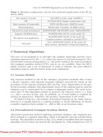
The changes necessary to implement this concept are visualized in the struc-
ture charts in Fig. 1. Instead of looping all elements and calculating the element
matrix individually, now all sets of elements are processed. For every set the
usual procedure to integrate the matrices is carried out, except on the lowest
level, i.e. as the innermost loop, a new loop over all elements in the current set
is introduced. This loop suits especially vector machines perfectly, as the cal-
culations inside are quite simple and, most important, consecutive steps do not
depend on each other. In addition the length of this loop, i.e. the size of the
element sets, can be chosen freely, to fill the processor’s vector pipes.
Please purchase PDF Split-Merge on www.verypdf.com to remove this watermark.
Computational Efficiency of Parallel Unstructured FE Simulations 93
loop elements in set
loop nodes of element
loop nodes of element
loop gauss points
shape functions, derivatives, etc.
group similar elements into sets
loop all elements
element calculation
loop all sets
assemble all element matrices
....
calculate stiffness
....
contributions
....
calculate stiffness
....
element calculation
assemble element matrix
loop nodes of element
shape functions, derivatives, etc.
loop nodes of element
loop gauss points
contributions
Fig. 1. Old (left) and new (right) structure of an algorithm to evaluate element ma-
trices
The only limitation for the size of the sets are additional memory require-
ments, as now intermediate results have to be stored for all elements in one
set. For a detailed description of the dependency of the size of the sets and the
processor type see Sect. 2.2.
2.2 Further Influences on the Efficiency
Programming Language & Array Management
It is well known that the programming language can have a large impact on
the performance of a scientific code. Despite considerable effort on other lan-
guages [3, 4] Fortran is still considered the best choice for highly efficient code
[5] whereas some features of modern programming languages, like pointers in C
or objects in C++, make vectorization more complicated or even impossible [2].
Especially the very general pointer concept in C makes it difficult for the
compiler to identify data-parallel loops, as different pointers might alias each
other. There are a few remedies for this problem like compiler flags or the restrict
keyword. The latter is quite new in the C standard and it seems that it is not
yet fully implemented in every compiler.
We have implemented the proposed concept for the calculation of the element
matrices in 5 different variants. The first four of them are implemented in C, the
last one in Fortran. Further differences are the array management and the use
of the restrict keyword. For a detailed description of the variants see Table 1.
Multi-dimensional arrays denote the use of 3- or 4-dimensional arrays to store
intermediate results, whereas one-dimensional arrays imply a manual indexing.
The results in Table 1 give the cpu time spent for the calculation of some
representative element matrix contributions standardized by the time used by
the original code. The positive effect of the grouping of elements can be clearly
seen for the vector processor. The calculation time is reduced to less than 3% for
all variants. On the other two processors the grouping of elements does not result
Please purchase PDF Split-Merge on www.verypdf.com to remove this watermark.
94 M. Neumann et al.
Table 1. Influences on the performance. Properties of the five different variants and
their relative time for calculation of stiffness contributions
orig var1 var2 var3 var4 var5
language C C C C C Fortran
array dimensions multi multi multi one one multi
restrict keyword restrict restrict
SX-6+
1
1.000 0.024 0.024 0.016 0.013 0.011
Itanium2
2
1.000 1.495 1.236 0.742 0.207 0.105
Pentium4
3
1.000 2.289 1.606 1.272 1.563 0.523
in a better performance for all cases. The Itanium architecture shows only an
improved performance for one dimensional array management and the variant
implemented in Fortran and the Pentium processor performs in general worse
for the new structure of the code. Only for the last variant the calculation time
is cut in half.
It can be clearly seen, that the effect of the restrict keyword varies for the dif-
ferent compilers/processors and also for one-dimensional and multi-dimensional
arrays. Using restrict on the SX-6+ results only in small improvements for one-
dimensional arrays, on the Itanium architecture the speed-up for this array man-
agement is even considerable. In contrast to this on the Pentium architecture the
restrict keyword has a positive effect on the performance of multi-dimensional
arrays and a negative effect for one-dimensional ones.
The most important result of this analysis is the superior performance of
Fortran. This is the reason we favor Fortran for performance critical scientific
code and use the last variant for our further examples.
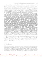
Size of the Element Sets
As already mentioned before the size of the element sets and with it the length of
the innermost loop needs to be different on different hardware architectures. To
find the optimal sizes on the three tested platforms we measured the time spent
in one subroutine, which calculates representative element matrix contributions,
for different sizes of the element sets (Fig. 2).
For the cache based Pentium4 processor the best performance is achieved
for very small sizes of the element sets. This is due to the limited size of cache
which usage is crucial for performance. The best performance for the measured
subroutine was achieved with 12 elements per set.
1
NEC SX-6+, 565 MHz; NEC C++/SX Compiler, Version 1.0 Rev. 063; NEC FOR-
TRAN/SX Compiler, Version 2.0 Rev. 305.
2
Hewlett Packard Itanium2, 1.3 GHz; HP aC++/ANSI C Compiler, Rev. C.05.50;
HP F90 Compiler, v2.7.
3
Intel Pentium4, 2.6 GHz; Intel C++ Compiler, Version 8.0; Intel Fortran Compiler,
Version 8.0.
Please purchase PDF Split-Merge on www.verypdf.com to remove this watermark.
Computational Efficiency of Parallel Unstructured FE Simulations 95
SX6 Itanium2
Pentium4
Size of one element set
Calculation time [sec]
512448384320256192128640
30
20
10
0
Fig. 2. Calculation time for one subroutine that calculates representative element
matrix contributions for different sizes of one element set
The Itanium2 architecture shows an almost constant performance for a large
range of sizes. The best performance is achieved for a set size of 23 elements.
For the vector processor SX-6+ the calculation time decrease for growing
sizes up to 256 elements per set, which corresponds to the size of the vector
registers. For larger sets the performance only varies slightly with optimal values
for multiples of 256.
2.3 Results
Concluding we would like to demonstrate the positive effect of the proposed
concept for the calculation of element matrices on a full CFD simulation. The
flow is the Beltrami-Flow (for details see [6]) and the unit-cube was discretized
by 32768 stabilized 8-noded hexahedral elements [7].
In Fig. 3 the total calculation time for 32 time steps of this example and
the fractions for the element calculation and the solver on the SX-6+ are given
for the original code and the full implementation of variant 5. The time spent
for the element calculation, formerly the major part of the total time, could be
reduced by a factor of 24.
This considerable improvement can also be seen in the sustained performance
given in Table 2 as percentage of peak performance. The original code not written
for any specific architecture has only a poor performance on the SX-6+ and
a moderate one on the other platforms. The new code, designed for a vector
processor, achieves for the complete element calculation an acceptable efficiency
of around 30% and for several subroutines, like the calculation of some stiffness
contributions, even a superior efficiency of above 70%. It has to be noted that
these high performance values come along with a vector length of almost 256
and a vector operations ratio of above 99.5%.
But also for the Itanium2 and Pentium4 processors, which were not the
main target architectures, the performance was improved significantly and for
Please purchase PDF Split-Merge on www.verypdf.com to remove this watermark.
96 M. Neumann et al.
20000
Calculation time [sec]
Variant 5
other
5000
10000
15000
0
ele. calc.
solver
Original
element calc. stiffness contr.
original var5 original var5
SX-6+ 0.95 29.55 0.83 71.07
Itanium2 8.68 35.01 6.59 59.71
Pentium4 12.52 20.16 10.31 23.98
Fig. 3. Split-up of total calculation
time for 32 time steps of the Beltrami
Flow on the SX-6+
Table 2. Efficiency of original and new
code in percent of peak performance
the Itanium2 the new code reaches around the same efficiency as on the vector
architecture.
3 Iterative Solvers
CCARAT uses external solvers such as Aztec to solve the linear system of equa-
tions. Most of the public domain iterative solvers are optimized for performance
only on cache based machines, hence they do not performance well on vector
systems. The main reason for this is the storage formats used in these packages,
which are mostly row or column oriented.
The present effort is directed at improving the efficiency of the iterative
solvers on vector machines. The most important kernel operation of any iterative
solver is the matrix vector multiplication. We shall look at the efficiency of this
operation, especially on vector architectures, where its performance is mainly
affected by the average vector length and the frequency of indirect addressing.
3.1 Sparse Storage Formats
Short vector length is a classical problem that affects the performance on vector
systems. The reason for short vector lengths in this case is the sparse storage
format used. Most of the sparse linear algebra libraries implement either a row
oriented or a column oriented storage format. In these formats, the non-zero
entries in each row or a column are stored successively. This number usually
turns out to be smaller than the effective size of the vector pipes on SX (which is
256 on SX-6+ and SX-8). Hence, both these formats lead to short vector lengths
at runtime. The only way to avoid this problem is to use a pseudo diagonal
format. This format ensures that, at least the length of the first few non-zero
pseudo diagonals is equivalent to the size of the matrix. Hence, it overcomes the
problem of short vector length. An example of such a format is the well known
jagged diagonal format (JAD). The performance data with row and diagonal
formats on SX-6+ and SX-8 is listed in Table 3.
Please purchase PDF Split-Merge on www.verypdf.com to remove this watermark.