Tài liệu High Performance Computing on Vector Systems-P6 pdf
Bạn đang xem bản rút gọn của tài liệu. Xem và tải ngay bản đầy đủ của tài liệu tại đây (1.47 MB, 30 trang )
A Hybrid LES/CAA Method for Aeroacoustic Applications 147
The zonal approach results in a pronounced improvement of the local ac-
curacy of the solution. The skin-friction coefficient distribution and the near
wall as well as the wake velocity profiles show a convincing agreement with the
experimental data.
The experience with the present global LES method evidences, that good re-
sults can be achieved if the resolution requirements are met [5]. For this reason,
the next step will be to concentrate on the improvement of the computational
setup. Since the outer part of the flow field over an airfoil is predominantly
two-dimensional and laminar, only a quasi-2d calculation will be performed in
this area in the next step. For this purpose, a 2D/3D coupling technique has
been developed for the structured solver. With this technique, it is possible to
increase the near wall resolution while keeping the overall computational cost
at a relatively low level. Next, hybrid RANS/LES coupling techniques are con-
templated for the improvement of the overall numerical method. Furthermore,
with respect to the simulation of the sound field the LES data from the zonal
approach will be postprocessed to determine the source terms of the acoustic
perturbation equations, which were already successfully used in [1].
6 CAA for Combustion Noise
This research project is part of the Research Unit FOR 486 “Combustion Noise”,
which is supported by the German Research Council (DFG). The objective of
the Institute of Aerodynamics of the RWTH Aachen University is to investigate
the origin of combustion noise and its mechanisms. The LES for the two-step
approach is performed by the Institute for Energy and Powerplant Technology
from Darmstadt University of Technology, followed by the CAA simulation to
compute the acoustical field. This hybrid LES/CAA approach is similar to that
in [1]. However, in this study the Acoustic Perturbation Equations are extended
to reacting flows. In flows, where chemical reactions have to be considered, the
application of such an approach is essential as the disparity of the characteristic
fluid mechanical and acoustical length scales is even more pronounced than in
the non-reacting case.
It is well known from the literature, e.g. [12, 13], that noise generated by com-
bustion in low Mach number flows is dominated by heat release effects, whereas
in jet or airframe noise problems the major noise contribution originates from the
Lamb vector (L
′
=(ω× u)
′
), which can be interpreted as a vortex force [14, 15].
In principle it is possible to treat this task by extending Lighthill’s Acoustic
Analogy to reacting flows as was done in the past [12, 13]. This, however, leads
to an inhomogeneous wave equation with an ordinary wave operator e.g. [13, 16],
which is valid for homogeneous mean flow only. Therefore, this approach is re-
stricted to the acoustic far field. The APE approach remedies this drawback. It is
valid in non-uniform mean flow and takes into account convection and refraction
effects, unlike the linearized Euler equations [14].
Please purchase PDF Split-Merge on www.verypdf.com to remove this watermark.
148 Q. Zhang et al.
7 Governing Equations
To derive the extended APE system the governing equations of mass, momen-
tum, and energy for reacting flows are rearranged such that the left-hand side
describes the APE-1 system [14], whereas the right-hand side (RHS) consists of
all non-linear flow effects including the sources related to chemical reactions.
∂ρ
′
∂t
+ ∇·(ρ
′
¯u +¯ρu
′
)=q
c
(1)
∂u
′
∂t
+ ∇ (¯u · u
′
)+∇
p
′
¯ρ
= q
m
(2)
∂p
′
∂t
− ¯c
2
∂ρ
′
∂t
= q
e
(3)
As was mentioned before, the heat release effect dominates the generation of
combustion noise. Therefore the investigations have been performed using q
e
only, i.e. assuming q
c
=0andq
m
=0.
7.1 Thermoacoustic Source Terms
In the proposed APE system the source term containing heat release effects
appears on the RHS of the pressure-density relation, i.e. q
e
. This term vanishes
when only isentropic flow is considered. However, due to the unsteady heat
release in a flame the isentropic pressure-density relation is no longer valid in
the combustion area. Nevertheless, it is this effect, which defines the major source
term in comparison to the sources (q
c
, q
m
) in the mass and momentum equations
within the APE system. Concerning the other source mechanisms, which lead
to an acoustic multipole behavior though it can be conjectured that they are of
minor importance in the far field. Using the energy equation for reacting flows
the pressure-density relation becomes:
∂p
′
∂t
− ¯c
2
∂ρ
′
∂t
= −¯c
2
·
∂ρ
e
∂t
=¯c
2
¯ρ
ρ
·
α
c
p
·
N
n=1
∂h
∂Y
n
ρ,p,Y
m
ρ
DY
n
Dt
+ ∇·q −
∂u
i
∂x
j
τ
ij
−∇ (uρ
e
) −
1
¯c
2
1 −
¯ρ¯c
2
ρc
2
·
Dp
Dt
−
p − ¯p
ρ
·
Dρ
Dt
+
−
γ − 1
γ
u ·∇¯ρ −
p
¯c
2
· u
∇¯p
¯p
−
∇¯ρ
¯ρ
(4)
where ρ
e
is defined as
ρ
e
=(ρ− ¯ρ) −
p − ¯p
¯c
2
(5)
Perturbation and time averaged quantities are denoted by a prime and a bar,
respectively. The volumetric expansion coefficient is given by α and c
p
is the
Please purchase PDF Split-Merge on www.verypdf.com to remove this watermark.
A Hybrid LES/CAA Method for Aeroacoustic Applications 149
specific heat capacity at constant pressure. For an ideal gas the equation α/c
p
=
(γ − 1)/c
2
holds. The quantity Y
n
is the mass fraction of the nth species, h the
enthalpy and q the heat flux.
7.2 Evaluation of the Thermoacoustic Source Terms
The investigations have been performed by considering q
e
only. Reformulating
the energy equation for a gas with N species [13] leads to
Dρ
Dt
=
1
c
2
Dp
Dt
+
α
c
p
·
N
n=1
∂h
∂Y
n
ρ,p,Y
m
ρ
DY
n
Dt
+ ∇·q −
∂u
i
∂x
j
τ
ij
(6)
Since the combustion takes place at ambient pressure and the pressure variations
due to hydrodynamic flow effects are of low order, the whole combustion process
can be assumed to be at constant pressure. From our analysis [15] and from
literature [13] it is known that combustion noise is dominated by heat release
effects and that all other source mechanisms are of minor importance. Assuming
combustion at constant pressure and neglecting all mean flow effects q
e
reduces to
sources, which are related to heat release effects, non-isomolar combustion, heat
flux and viscous effects. Adding up all these sources under the aforementioned
restrictions the RHS of the pressure-density relation can be substituted by the
total time derivative of the density multiplied by the square of the mean speed
of sound and the ratio of the mean density and the density
q
e
=¯c
2
¯ρ
ρ
·
α
c
p
·
N
n=1
∂h
∂Y
n
ρ,p,Y
m
ρ
DY
n
Dt
+ ∇·q −
∂u
i
∂x
j
τ
ij
(7)
=¯c
2
¯ρ
ρ
Dρ
Dt
. (8)
8NumericalMethod
8.1 LES of the Turbulent Non-Premixed Jet Flame
In the case of non-premixed combustion, the chemical reactions are limited by
the physical process of the mixing between fuel and oxidizer. Therefore, the
flame is described by the classical mixture fraction approach by means of the
conserved scalar f. The filtered transport equations for LES are solved on a stag-
gered cylindrical grid of approximately 10
6
cells by FLOWSI, an incompressible
finite-volume solver. A steady flamelet model in combination with a presumed β-
Pdf approach is used to model the turbulence chemistry interaction. The subgrid
stresses are closed by a Smagorinsky model with a dynamic procedure by Ger-
mano [17]. For the spatial discretization, a combination of second-order central
differencing and total-variation diminishing schemes is applied [18]. The time
integration is performed by an explicit third-order, low storage Runge-Kutta
Please purchase PDF Split-Merge on www.verypdf.com to remove this watermark.
150 Q. Zhang et al.
scheme. At the nozzle exit, time averaged turbulent pipe flow profiles are super-
imposed with artificially generated turbulent fluctuations [19], while the coflow
is laminar.
8.2 Source Term Evaluation
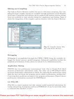
The total time derivative of the density, which defines the major source term of
the APE system, has been computed by the unsteady flow field in a flame region
where the main heat release occurs (Fig. 12).
Fig. 12. Contours of the total
time derivative of the density
(Dρ/Dt)att = 100 in the
streamwise center plane
8.3 Grid Interpolation
Since the source terms have been calculated on the LES grid they need to be
interpolated on the CAA grid. Outside the source area the APE system becomes
homogeneous. This means, the RHS is defined in the source region only. There-
fore, the CAA domain has been decomposed into a multiblock domain such that
one block contains the entire source area. This procedure possesses the advan-
tages that the interpolation from the LES grid to the CAA source block is much
faster than onto the whole CAA domain and that the resulting data size for the
CAA computation can be reduced dramatically. The data interpolation is done
with a trilinear algorithm.
8.4 CAA Computation
For the CAA computation this proposed APE-System has been implemented
into the PIANO (Perturbation Investigation of Aeroacoustic Noise) Code from
the DLR (Deutsches Zentrum f¨ur Luft- und Raumfahrt e.V.).
The source terms on the right-hand side of the APE system has to be interpolated
in time during the CAA computation. Using a quadratic interpolation method
at least 25 points per period are required to achieve a sufficiently accurate distri-
bution. Hence, the maximal resolvable frequency is f
max
=1/(25Δt) = 800Hz
since the LES solution comes with a time increment of Δt =5· 10
−5
s [20]. This
Please purchase PDF Split-Merge on www.verypdf.com to remove this watermark.
A Hybrid LES/CAA Method for Aeroacoustic Applications 151
frequency is much smaller than the Nyquist frequency. The CAA code is based on
the fourth-order DRP scheme of Tam and Webb [21] for the spatial discretization
and the alternating LDDRK-5/6 Runge-Kutta scheme for the temporal integra-
tion [22]. At the far field boundaries a sponge-layer technique is used to avoid
unphysical reflections into the computational domain.
Solving the APE system means to solve five equations (3D) for the pertur-
bation quantities ρ
′
,u
′
,v
′
,w
′
and p
′
per grid point and time level. No extra
equations for viscous terms and chemical reaction need to be considered since
these terms can be found on the RHS of the APE system and are provided by
the LES within the source region. On the other hand the time step within the
CAA computation can be chosen much higher than in the LES. This means,
using a rough estimation, that the ratio of the computation times between LES
and CAA is approximately t
LES
/t
CAA
≈ 4/1.
9Results
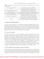
Figure 13 shows a snapshot of the acoustic pressure field in the streamwise center
plane at the dimensionless time t = 100. The source region is evidenced by the
dashed box. This computation was done on a 27-block domain using approx-
imately 4 × 10
6
grid points, where the arrangement of the blocks is arbitrary
provided that one block contains all acoustical sources.
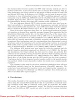
The acoustic directivity patterns (Fig. 14) are computed for different fre-
quencies on a circle in the z = 0 plane with a radius R/D = 17 whose center
point is at x =(10, 0, 0). The jet exit diameter is denoted by D. From 150
◦
to
210
◦
the directivity data is not available since this part of the circle is outside
of the computational domain. In general an acoustic monopole behaviour with
a small directivity can be observed since this circle is placed in the acoustic near
field.
Fig. 13. Pressure contours of the APE
solution at t = 100 in the streamwise
center plane
Please purchase PDF Split-Merge on www.verypdf.com to remove this watermark.
152 Q. Zhang et al.
p’
0
30
60
90
120
150
180
210
240
270
300
330
0 2E-06 4E-06
209Hz
p’
0
30
60
90
120
150
180
210
240
270
300
330
0 2E-06 4E-06
340Hz
p’
0
30
60
90
120
150
180
210
240
270
300
330
0 2E-06 4E-06
601Hz
p’
0
30
60
90
120
150
180
210
240
270
300
330
0 2E-06 4E-06
680Hz
p’
0
30
60
90
120
150
180
210
240
270
300
330
0 2E-06 4E-06
758Hz
Fig. 14. Directivity patterns for different frequencies
10 Conclusion
The APE system has been extended to compute noise generated by reacting flow
effects. The heat release per unit volume, which is expressed in the total time
derivative of the density, represents the major source term in the APE system
when combustion noise is analyzed. The main combustion noise characteristic,
i.e., the monopole nature caused by the unsteady heat release, could be verified.
In the present work we have demonstrated that the extended APE System in
conjunction with a hybrid LES/CAA approach and with the assumptions made,
is capable of simulating an acoustic field of a reacting flow, i.e., of a non-premixed
turbulent flame.
Acknowledgements
The authors would like to thank the Institute for Energy and Powerplant Tech-
nology from Darmstadt University of Technology for providing the LES data of
the non-premixed flame.
References
1. Ewert, R., Schr¨oder, W.: On the simulation of trailing edge noise with a hybrid
LES/APE method. J. Sound and Vibration 270 (2004) 509–524
2. Wagner, S., Bareiß, R., Guidati, G.: Wind Turbine Noise. Springer, Berlin (1996)
3. Howe, M.S.: Trailing edge noise at low mach numbers. J. Sound and Vibration
225 (2000) 211–238
Please purchase PDF Split-Merge on www.verypdf.com to remove this watermark.
A Hybrid LES/CAA Method for Aeroacoustic Applications 153
4. Davidson, L., Cokljat, D., Fr¨ohlich, J., Leschziner, M., Mellen, C., Rodi, W.: LES-
FOIL: Large Eddy Simulation of Flow Around a High Lift Airfoil. Springer, Berlin
(2003)
5. El-Askary, W.A.: Zonal Large Eddy Simulations of Compressible Wall-Bounded
Flows. PhD thesis, Aerodyn. Inst. RWTH Aachen (2004)
6. Poinsot, T.J., Lele, S.K.: Boundary conditions for direct simulations of compress-
ible viscous flows. J. Comp. Phys. 101 (1992) 104–129
7. Ewert, R., Meinke, M., Schr¨oder, W.: Computation of trailing edge noise via LES
and acoustic perturbation equations. Paper 2002-2467, AIAA (2002)
8. Schr¨oder, W., Meinke, M., El-Askary, W.A.: LES of turbulent boundary layers.
In: Second International Conference on Computational Fluid Dynamics ICCFD II,
Sydney. (2002)
9. El-Askary, W.A., Schr¨oder, W., Meinke, M.: LES of compressible wall bounded
flows. Paper 2003-3554, AIAA (2003)
10. Schr¨oder, W., Ewert, R.: Computational aeroacoustics using the hybrid approach
(2004) VKI Lecture Series 2004-05: Advances in Aeroacoustics and Applications.
11. W¨urz, W., Guidati, S., Herr, S.: Aerodynamische Messungen im Laminarwind-
kanal im Rahmen des DFG-Forschungsprojektes SWING+ Testfall 1 und Testfall
2 (2002) Inst. f¨ur Aerodynamik und Gasdynamik, Universit¨at Stuttgart.
12. Strahle, W.C.: Some results in combustion generated noise. J. Sound and Vibration
23 (1972) 113–125
13. Crighton, D., Dowling, A., Williams, J.F.: Modern Methods in analytical acoustics,
Lecture Notes. Springer, Berlin (1996)
14. Ewert, R., Schr¨oder, W.: Acoustic perturbation equations based on flow decom-
position via source filtering. J. Comp. Phys. 188 (2003) 365–398
15. Bui, T.P., Meinke, M., Schr¨oder, W.: A hybrid approach to analyze the acoustic
field based on aerothermodynamics effects. In: Proceedings of the joint congress
CFA/DAGA ’04, Strasbourg. (2004)
16. Kotake, S.: On combustion noise related to chemical reactions. J. Sound and
Vibration 42 (1975) 399–410
17. Germano, M., Piomelli, U., Moin, P., Cabot, W.H.: A dynamic subgrid-scale vis-
cosity model. Phys. of Fluids 7 (1991) 1760–1765
18. Waterson, N.P.: Development of a bounded higher-order convection scheme for
general industrial applications. In: Project Report 1994-33, von Karman Institute.
(1994)
19. Klein, M., Sadiki, A., Janicka, J.: A digital filter based generation of inflow data
for spatially developing direct numerical or large eddy simulations. J. Comp. Phys.
186 (2003) 652–665
20. D¨using, M., Kempf, A., Flemming, F., Sadiki, A., Janicka, J.: Combustion les for
premixed and diffusion flames. In: VDI-Berichte Nr. 1750, 21. Deutscher Flam-
mentag, Cottbus. (2003) 745–750
21. Tam, C.K.W., Webb, J.C.: Dispersion-relation-preserving finite difference schemes
for computational acoustics. J. Comp. Phys. 107 (1993) 262–281
22. Hu, F.Q., Hussaini, M.Y., Manthey, J.L.: Low-dissipation and low-dispersion
runge-kutta schemes for computational acoustics. J. Comp. Phys. 124 (1996)
177–191
Please purchase PDF Split-Merge on www.verypdf.com to remove this watermark.
Please purchase PDF Split-Merge on www.verypdf.com to remove this watermark.
Simulation of Vortex Instabilities
in Turbomachinery
Albert Ruprecht
Institute of Fluid Mechanics and Hydraulic Machinery, University of Stuttgart,
Pfaffenwaldring 10, D-70550 Stuttgart, Germany,
Abstract The simulation of vortex instabilities require a sophisticated modelling of
turbulence. In this paper a new turbulence model for Very Large Eddy Simulation is
presented. Its main characteristic is an adaptive filtering technique which can distin-
guish between numerically resolved and unresolved parts of the flow. This unresolved
part is then modelled with extended k – ε model of Chen and Kim. VLES is applied to
the simulation of vortex instabilities in water turbines. As a first example the unsteady
vortex flows in draft tube is shown and in a second application the unstable flow in
a pipe trifurcation is calculated. These cases cannot be predicted accurately with clas-
sical turbulence models. Using the new technique, these complex phenomena are well
predicted.
Nomenclature
f [− ] filter function
h
max
[ m ] local grid size
k [m
2
/s
2
] turbulent kinetic energy
L [ m ] Kolmogorov length scale
P
k
[− ] production term
u [m/s ] local velocity
U
i
[m/s] filtered velocity
¯
U
i
[m/s ] averaged velocity
¯
P [ Pa ] averaged pressure
τ
ij
[ Pa ] Reynolds stresses
α [− ] model constant
Δ [ m ] resolved length scale
Δt [s] time step
ε [m
2
/s
3
] dissipation rate
ν [m
2
/s] kinematic viscosity
ν
t
[m
2
/s ] turbulent viscosity
ΔV [m
2
or m
3
] size of the local element
Please purchase PDF Split-Merge on www.verypdf.com to remove this watermark.
156 A. Ruprecht
Subscripts and Superscripts
ˆ modeled
i covariant indices, i =1, 2, 3
1 Introduction
The flow in hydraulic turbo machinery is quite complicated, especially under
off-design conditions the flow tends too get unsteady and complicated vortex
structures occur, which can get unstable. The prediction of these vortex instabil-
ities is quite challenging, since an inaccurate prediction can completely suppress
the unsteady motion and result in a steady state flow situation.
It is well known that still one of the fundamental problems of Computa-
tional Fluid Dynamics (CFD) is prediction of turbulence. Reynolds-averaged
Navier-Stokes (RANS) equations are established as a standard tool for indus-
trial simulations and analysis of fluid flows, although it means that the complete
turbulence behaviour has to be enclosed within appropriate turbulence model
which takes into account all turbulence scales (from the largest eddies to the
Kolmogorov scale). Consequently defining a suitable model for prediction of
complex, especially unsteady, phenomena is very difficult.
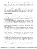
The highest accuracy for resolving all turbulence scales offers a Direct Nu-
merical Simulation (DNS). It requires a very fine grid and carrying out 3D simu-
lations for complex geometries and flow with high Reynolds number is nowadays
time consuming even for high performance computers, Fig. 1. Therefore, DNS is
unlikely to be applied to the flow of practical relevance in the near future.
Large Eddy Simulation (LES) starts to be a mature technique for analyz-
ing complex flow, although its major limitation is still expensive computational
cost. In the “real” LES all anisotropic turbulent structures are resolved in the
computation and only the smallest isotropic scales are modelled. It is schemat-
ically shown in Fig. 2. The models used for LES are simple compared to those
used for RANS because they only have to describe the influence of the isotropic
scales on the resolved anisotropic scales. With increasing Reynolds number the
small anisotropic scales strongly decrease becoming isotropic and therefore not
Fig. 1. Degree of turbulence modelling
and computational effort for the different
approaches
Please purchase PDF Split-Merge on www.verypdf.com to remove this watermark.
Simulation of Vortex Instabilities in Turbomachinery 157
resolvable. There are many “LES” of engineering relevant flows in the litera-
ture, although they can be characterised as unsteady RANS (URANS) due to
the fact that they only resolve unsteady mean flow not taking into account any
turbulence structure.
If there is a gap in the turbulence spectrum between the unsteady mean flow
and the turbulent flow, a “classical” RANS i.e. URANS models can be applied,
as they are developed for modelling the whole range of turbulent scales, Fig. 2.
It also means that they are not suitable for prediction and analysis of many
unsteady vortex phenomena.
Contrary, if there is no spectral gap and even one part of the turbulence can
be numerically resolved, we can use Very Large Eddy Simulation (VLES). It is
very similar to the LES, only that a smaller part of the turbulence spectrum is
resolved and the influence of a larger part of the spectrum has to be expressed
with the model, see Fig. 2. Nowadays it seems to be a promising compromise for
simulation of industrial flow problems with reasonable computational time and
costs.
In this paper the development of a VLES turbulence model is presented. It is
based on the extended k – ε model of Chen and Kim [1]. Applying an appropriate
filtering technique the new turbulence model distinguishes between resolved and
modelled part of the turbulence spectrum. Because of its adaptive characteristic
it can be applied for the whole range of turbulence modelling approaches from
RANS to DNS.
Here presented applications of the new adaptive turbulence model are simu-
lation of the flow in draft tube and pipe trifurcation. In both cases an unsteady
motions are observed and computationally well predicted.
Fig. 2. Modelling approaches for RANS and LES
Please purchase PDF Split-Merge on www.verypdf.com to remove this watermark.
158 A. Ruprecht
2 Simulation Method
2.1 Governing Equations
In this work an incompressible fluid with constant properties is considered. The
governing equations describing this incompressible, viscous and time dependent
flow are the Navier-Stokes equations. They express the conservation of mass and
momentum. In the RANS approach, the same equations are time or ensemble
averaged leading to the well known RANS equations:
∂
¯
U
i
∂t
+
¯
U
j
∂
¯
U
i
∂x
j
= −
∂
¯
P
∂x
i
+ ν∇
2
¯
U
i
−
∂τ
ij
∂x
j
(1)
∂
¯
U
i
∂x
i
=0 (2)
In RANS τ
ij
expresses the Reynolds stress tensor which is unknown and
has to be modelled. The task of turbulence modelling is in the formulation and
determination of suitable relations for Reynolds stresses. Details of the new
VLES approach are described in Sect. 3.
2.2 Numerical Method
The calculations are performed using the program FENFLOSS (Finite Element
based Numerical FLOw Simulation System) which is developed at the Institute
of Fluid Mechanics and Hydraulic Machinery, University of Stuttgart.
It is based on the Finite Element Method. For spatial domain discretisation
8-node hexahedral elements are used. Time discretisation involves a three-level
fully implicit finite difference approximation of 2nd order. For the velocity com-
ponents and the turbulence quantities a trilinear approximation is applied. The
pressure is assumed to be constant within element. For advection dominated
flow a Petrov-Galerkin formulation of 2nd order with skewed upwind orientated
weighting functions is used.
For the solution of the momentum and continuity equations a segregated
algorithm is used. It means that each momentum equation is handled indepen-
dently. They are linearised and the linear equation system is solved with the
conjugated gradient method BICGSTAB2 of van der Vorst [12] with an incom-
plete LU decomposition (ILU) for preconditioning. The pressure is treated with
the modified Uzawa pressure correction scheme [14]. The pressure correction is
performed in a local iteration loop without reassembling the system matrices
until the continuity error is reduced to a given order.
After solving the momentum and continuity equations, the turbulence quan-
tities are calculated and a new turbulence viscosity is gained. The k and ε-
equations are also linearised and solved with BICGSTAB2 algorithm with ILU
preconditioning. The whole procedure is carried out in a global iteration until
convergence is obtained. For unsteady simulation the global iteration has to be
performed for each time step. FENFLOSS flow chart is shown in Fig. 3.
Please purchase PDF Split-Merge on www.verypdf.com to remove this watermark.