Tài liệu System programming basics doc
Bạn đang xem bản rút gọn của tài liệu. Xem và tải ngay bản đầy đủ của tài liệu tại đây (7.03 MB, 1,258 trang )
System programming basics
System Programming
Basics
1
1
n the first part of this book we'll discuss the basics of system programming. We'll talk about the purpose of system
programming and the methods and tools used in system programming. We'll also explain the PC's basic structure and the
interaction between hardware, BIOS and DOS.
What Is System Programming?
S
ome users, regardless if they're beginners or experienced programmers, believe system programming is a programming
technique that converts a problem into a finished program. Others think system programming means developing programs
for one particular computer system.
Application programming versus system programming
Although both answers are incorrect, the second is more accurate than the first. The most accurate description of system
programming can be derived from the term application programming. This type of programming refers to information
management and presentation within a program. This involves arranging this information into lists, etc., and processing this
information. The algorithms used for this are system independent and can be defined for almost any computer.
The way this information is passed to a program, and the way the information is displayed or printed are system dependent.
System programming controls any hardware that sends information to, or receives information from, the computer. However,
since this information must be processed, developing programs for PCs requires both application programming and system
programming. Programming hardware requires the interaction of system programming, DOS, and the ROM-BIOS (more on
this later).
The Three-Layer Model
O
ne of the most important tasks of system programming involves accessing the PC hardware. However, the access doesn't
have to occur immediately, with the program turning directly to the hardware, which is similar to accessing the processor
on a video card. Instead, the program can use the ROM-BIOS and DOS to negotiate hardware access. The ROM-BIOS and
DOS are software interfaces, which were created specifically for hardware management.
Advantages of the DOS and BIOS interfaces
The greatest advantage of using DOS or BIOS is that a program doesn't have to communicate with the hardware on its own.
Instead, it calls a ROM-BIOS routine that performs the required task. After the task is completed, the ROM-BIOS returns
status information to the program as needed. This saves the programmer a lot of work, because calling one of these functions
is faster than directly accessing the hardware.
There's another advantage to using these interfaces. The ROM-BIOS and DOS function interfaces keep a program isolated
from the physical properties of the hardware. This is very important because monochrome graphic cards, such as the MDA
and Hercules cards, must be programmed differently from color graphic cards, such as the CGA, EGA, VGA, and Super VGA.
If you want a program to support all these cards, you must implement individual routines for each card, which is very
time-consuming. The ROM-BIOS functions used for video output are adapted to the resident video card, so the program can
call these functions without having to adapt to the video card type.
1. System Programming Basics
I
1. System Programming Basics
2
ROM-BIOS
The BIOS offers functions for accessing the following devices:
Ø Video cards Ø RAM (extended memory) Ø Diskettes Ø Hard drives
Ø Serial ports Ø Parallel ports Ø Keyboard Ø Battery-operated realtime clock
As this illustration shows, the ROM-BIOS can
be viewed as a layer overlapping the hardware.
Although you can bypass the ROM-BIOS and
directly access the hardware, generally you
should use the ROM-BIOS functions because
they are standardized and can be found in
every PC. The ROM-BIOS, as its name
indicates, is in a ROM component on the
computer's motherboard. The moment you
switch on your computer, the ROM-BIOS is
available (see Chapter 3 for more information).
DOS interface
Along with BIOS, DOS provides functions for
accessing the hardware. However, since DOS
views hardware as logical devices instead of
physical devices, DOS functions handle hardware differently. For example, the ROM-BIOS views disk drives as groups of
tracks and sectors, but DOS views these drives as groups of files and directories. If you want to view the first thousand
characters of a file, first you must tell the ROM-BIOS the location of the file on the drive. With DOS functions, you simply
instruct DOS to open a file on drive A:, C:, or whatever device, and display the first thousand characters of this file.
Access often occurs through BIOS functions used by DOS. However, sometimes DOS also accesses hardware directly, but
you don't have to worry about this when you call a DOS function.
Which functions should you use?
We'll show you later how to call DOS and BIOS functions. First, however, we must determine which hardware access to use.
We have the option of direct hardware programming, calling BIOS functions and calling DOS functions. First, you don't
always have a choice between direct hardware programming and BIOS and DOS functions. Many tasks aren't supported by
the BIOS or DOS functions. For example, if you want your video card to draw circles or lines, you won't find the appropriate
functions in DOS or the BIOS. You must use direct hardware programming or purchase a commercial software library that
contains this program code.
Choosing between BIOS and DOS
When either a BIOS function or a DOS function can be used, base your decision on the current situation. Use DOS functions
if you want to work with files. If you want to format a diskette, you must use the appropriate BIOS functions. This is similar
to displaying characters on the screen. If you want to redirect your program output to a file (e.g., DIR >LIST.TXT), you must
use DOS functions. Only DOS functions automatically perform this redirection. The BIOS functions provide better control
of the screen (e.g., cursor placement). So, the situation determines which function you should use.
Slowing access
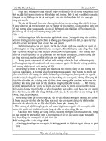
However, in some instances, both the BIOS functions and DOS functions are at a disadvantage because of slow execution
speed. As the number of software layers, which must be negotiated before hardware access occurs, increases, the programs
become longer. If the hardware must access a program that reads a file through BIOS and DOS, a hard drive's data transfer
rate can decrease a maximum of 80 percent.
Application program
DOS
BIOS
Hardware
The three layer
model
1. System Programming Basics
3
This problem is caused by the way the layers are handled. Before the call can be passed to the next level, parameters must
be converted, information must be loaded from internal tables, and buffer contents must be copied. The time needed for this
passage is called overhead. So, as overhead increases, so does the programmer's work.
As a result, when maximum execution speed is required and direct hardware programming is relatively simple, programmers
often use direct access instead of the BIOS and DOS. The best example of this is character output in text mode. Almost all
commercial applications choose the most direct path to the hardware because BIOS and DOS output functions are too slow
and inflexible. Direct video card access in text mode is quite easy (refer to Chapter 4 for more information), although graphic
mode output offers more challenges. Later in this chapter you'll learn how to call the DOS and BIOS functions and how to
directly access the hardware of the PC.
Basics Of PC Hardware
I
n this section we'll examine some of the basic concepts of PC architecture, which lead all the way to the system programming
level. Knowing something about the hardware will make it easier to understand some of the programming problems
discussed later in this book.
Birth of the PC
When the PC appeared on the market, much of what PC users take for granted today was inconceivable. The concept of having
a flexible computer on a desktop wasn't new; companies much smaller than IBM had already introduced similar computers.
IBM had just completed work on its System/23 DataMaster. However, the DataMaster was equipped with an 8085 8-bit
processor from Intel, which was outdated. In 1980, the 16-bit processor was introduced and IBM began planning a new,
revolutionary machine.
Choosing a processor
The 8086 processor and 8088 processors from Intel were the first representatives of the new 16-bit processors. Both had 16-
bit registers. This meant they could access 1 megabyte memory addresses instead of the old 64K memory addresses. A
megabyte was an unimaginable amount of memory in 1980, just as 1 Gigabyte of RAM is still unimaginable to many today.
Another reason developers were anxious to use the 8086 and 8088 processors was that many support chips already existed.
Obviously this saved a lot of development time. Also, both processors were supported by an operating system and an
implementation of the BASIC language, which was developed by Microsoft Corporation.
CPU
Expansion slots
Support chips
BUS
BUS
Memory
SIMM module
Block diagram
of your PC's
hardware
1. System Programming Basics
4
The developers chose the 8088 over the 8086 because, while the 8088 worked on a 16-bit basis internally, it only
communicated with the outside world using an 8-bit data bus. Since the 8-bit DataMaster data bus already existed, the 8088
was the obvious choice. This bus connects the motherboard of the PC, where the processor and its support chips are resident,
to the memory and the expansion boards, which are plugged into the expansion slots.
The Bus
Although the bus is vital to the operation of the computer system, the development of the PC bus represents one of the darkest
moments in the history of the PC. Although IBM tried to create an open system and publish all technical information, it
neglected to document the exact sequence of the bus signals, probably assuming that no one would need or want this
information. However, the openness of the PC and the option of easily adding expansion boards and more hardware added
to the PC's success on the market. Many users quickly took advantage of this, buying IBM expansion boards and third-party
compatible boards. The PC has its entire data and address bus on the outside; the bus connects to RAM, the various expansion
boards, and some support chips.
Operating the PC bus
The bus is basically a cable with 62 lines, from which data are loaded into memory by the processor, and through which data
can be transported to the processor. The bus consists of the data bus and the address bus. When memory is accessed, the
processor puts the address of the desired memory location on the address bus, with the individual lines indicating a binary
character. Each line can be only a 0 or a 1. Together, the lines form a number that specifies the address of the memory location.
The more lines that are available, the greater the maximum address and the greater the memory that can be addressed in this
way. Twenty lines were available on the original address bus because with 20 bits you can address 1 megabyte of memory,
which corresponds to the processor's performance.
The actual data are sent over the data bus. The first data bus was only 8 bits wide, so it could transfer only one byte at a time.
If the processor wanted to discard the contents of a 16-bit register or a 16-bit value in memory, it had to split the register or
value into two bytes and transfer one byte at a time.
Although theoretically this sounds simple, it's a complicated procedure. Along with the data and address buses, almost two
dozen other signal lines communicate between the processor and memory. All the boards communicate with the bus. When
a board takes responsibility for the specified address, it must send an appropriate signal to the processor. At this point, all
the other boards separate from the rest of the communication and wait for the beginning of the next data transfer cycle.
Using expansion boards always leads to problems. This usually occurs when two boards claim the same address range or there
are overlapping address ranges. The DIP switches on these boards let you specify the address range. One board must be
reconfigured to avoid conflict with the other board.
As a system programmer, you'll never encounter bus signals. Bus performance usually isn't important to system programming.
The bus signal timing is very important to expansion board manufacturers. Their products must follow this protocol to
function in the PC. However, this is the protocol that IBM never published. So, the manufacturers must measure the signal
sequences by using existing cards and then imitate those cards.
AT bus
In 1991, the IEEE (Institute of Electrical and Electronic Engineers) submitted an international standard for the AT bus. The
PC bus was limited by its 8-bit width. When the AT appeared on the market, it included a 16-bit bus that was compatible with
the older bus. That's why the old PC 8-bit boards can be used with the new 16-bit boards in one device. Obviously, the 16-bit
boards are much faster because they can transfer the same data in half the time it would take an 8-bit board.
The address bus was expanded to 24 bits, so the AT can address 16 megabytes of memory. Also, higher clock signal speed
increased bus transfer time. From 4.77 MHz on the PC, the AT speed increased to 8 MHz. However, that's as fast as the AT
address bus can handle information, although Intel processor speeds have reached the 100 MHz limit. As a result, the bus
is a bottleneck, through which the data will never be transferred quickly enough between memory and the processor. Modern
hard drives have a higher data transfer rate than the bus.
1. System Programming Basics
5
Wait state
The wait state signals found in some expansion boards give slow boards more time to deliver data to the processor. This is
also one reason why the AT bus resulted in more powerful successors like the Micro Channel bus and the EISA bus, which
haven't been very successful on the market for other reasons. At first there wasn't a generic name for the AT bus. However,
when competition appeared on the market, the bus was assigned the name Industry Standard Architecture bus, or ISA bus.
Problems with 16-bit boards on the AT bus
Since many 386es and 486es have an ISA bus, many problems in the PC can be traced to this bus. For example, the coexistence
of 8-bit and 16-bit expansion boards within a PC causes problems if the address range for which these boards are responsible
is located within any area of 128K. The problem starts at the beginning of a data transfer when a 16-bit board has to signal
from a control line that it can take a 16-bit word from the bus and, unlike an 8-bit board, doesn't depend on the transfer being
split into two bytes. However, the board must send this signal when it cannot even be aware the address on the data bus is
intended for it and requires an answer. Of the 24 address lines that carry the desired address, only lines A17 to A23 have been
correctly initialized to this point. This means the board only recognizes bits 17 to 23. These bits cover a complete 128K region,
regardless of what might follow in address bits 0 to 16. So for the moment, the board only knows whether the memory address
is located in the 0K-127K region, the 128K-255K region, etc.
If the 16-bit board sends the signal for a 16-bit transfer at this moment, it's speaking for all other boards within this region.
They experience this in the next moment, because after address bits 0 to 16 have arrived on the bus, the intended board will
be determined. If it really is the 16-bit board, no problems occur. However, if an 8-bit board was intended, the 16-bit board
will simply separate from the rest of the transfer, leaving the 8-bit board by itself. However, the 8-bit board won't be able to
manage the transfer because it's only set for 8-bit transfers. So, the expansion board cannot accept the data as sent.
PC BUS and VESA Local Bus
Considering the limitations of the AT bus and the inability of the EISA and MCA bus to gain market share, developers devised
other bus concepts. The VESA Local bus (VL bus) was first. It was designed and publicized by the independent VESA
Committee. The members of the VESA committee made it their business to define standards for graphic cards, so they didn't
really have anything at all to do with PC bus design. However, graphic cards suffer from the low speed of the AT bus. That's
why the VESA committee made the suggestion for a faster bus, the VESA local bus.
Unlike the EISA, MCA and PCI buses, the VL bus does not replace the ISA bus, instead, it complements it. A PC with a VL
bus has a normal ISA bus and the appropriate slots for expansion cards. However, there are also one or two additional slots
for cards designed for the VL bus, usually graphic cards. Only these slots are connected to the CPU through the VL bus so
the other slots are left undisturbed and ISA cards can perform their work.
The VL bus is a local bus. Unlike the ISA bus, it is directly coupled to the CPU. On the one hand, that gives the bus a much
higher clock speed (that of the CPU), but it also makes the bus dependent, both on the control lines of the CPU and on the
clock. Along with these drawbacks, the specifications of the VESA committee aren't very well considered. As a result, the
VL bus will not make the grade in the long run. Although some 486 systems often have this bus type, its popularity has fallen.
Clearly, the bus of the future remains Intel's PCI bus (Peripheral Component Interconnect). It represents a modern bus that
is superior to the ISA bus not only with regard to clock speed and a larger bus width. Finally, the PCI is a bus that automatically
synchronizes/tunes installed expansion cards regarding their port addresses, DMA channels and interrupts. The user no longer
has to deal with this issue.
The PCI bus is independent from the CPU because a PCI bus controller is always interconnected with the CPU and the PCI
bus. That makes it possible to use the PCI bus in systems that aren't based on an INTEL processor, such as an Alpha processor
from DEC. In the future, the Power Macintosh with the PowerPC processor is also supposed to be equipped with a PCI bus.
PCI upgrade cards work reliably in all systems equipped with a PCI bus and can be exchanged. Only the software drivers have
to be adapted to the host system, i.e., the CPU. Also, the PCI bus is not dependent on the clock of the CPU, because the PCI
bus controller separates it from the CPU. If you add a newer, faster CPU to your computer, you don't have to worry about
1. System Programming Basics
6
your installed upgrade cards not being able to handle the higher clock speeds. Because the CPU and PCI bus are separate,
the higher clock rates don't even affect them.
Pentium computers are almost exclusively equipped with PCI buses. The PCI bus is also becoming increasingly popular with
486 boards. Although you cannot operate an ISA card in a PCI slot, this doesn't mean you have to do without ISA cards on
most systems with a PCI bus. Often a board with a PCI bus will have a "PCI to ISA bridge". This is a chip that is interconnected
to the various ISA slots and the PCI bus controller. Its job is to convert signals from the PCI bus to the ISA bus. This allows
you to continue running your ISA cards under the protection of the PCI bus.
Although the future belongs to the PCI bus, the ISA bus and ISA expansion boards will still be popular. Not all expansion
boards require the high transfer rates made possible by the PCI bus. However, SCSI and network cards will be attached to
the PCI bus in ever greater numbers in the future (especially for graphics). The speed advantage of this bus system is
particularly noticeable with these cards so the hardware can keep up with the steadily increasing speed of the processor.
Controllers
Developers supplied the processor with additional chips to handle tasks the processor cannot handle on its own. These support
chips are called controllers because they control a part of the hardware for the processor and perform many tasks. This enables
the processor to concentrate on other tasks. The following pages describe these controllers and the chips initially selected by
IBM. Programmable controllers are indicated in the book.
DMA controller (8237)
DMA is an acronym for Direct Memory Access. This technique transfers data directly to memory by using a device (e.g., a
hard drive). This method seems to work much faster than the normal method, in which the processor prompts the hardware
for each word or byte and then sends the word or byte to memory. Actually, the DMA controller's advantages are evident only
with slow processors because the DMA is linked to the bus speed.
Today's processors, which work more than five times as fast as their bus, barely benefit from DMA transfer because the DMA
controller in the PC is obsolete. So, the DMA controller cannot even be used for one of the most interesting areas of
programming, which is moving large amounts of data from conventional RAM to video RAM (RAM on the video card). This
chip is still found in all PCs although it isn't used for its original purpose, which is data transfer between disk drives and
memory. ATs have two DMA controllers.
The PC is includes DRAM (dynamic RAM) instead of SRAM (static RAM). DRAMs lose their contents unless the system
continually refreshes the RAM. The DMA controllers in AT systems perform this RAM refresh instead of the processors.
Interrupt controller (8259)
The interrupt controller is important for controlling external devices, such as the keyboard, hard drive or serial port. Usually
the processor must repeatedly prompt a device, such as the keyboard, in short intervals to react immediately to user input and
pass this input to the program currently being executed. However, this continual prompting, also called polling, wastes
processor time because the user doesn't press a key as often as the processor polls the keyboard. However, the less often the
processor prompts the keyboard, the longer it takes until a program notices that a key has been pressed. This obviously defeats
the purpose, since the system is supposed to react promptly.
Hardware interrupt
The PC takes another route. Instead of the processor repeatedly prompting the devices, the devices report activity to the
processor. This is an example of a hardware interrupt, because at that exact moment the processor interrupts the execution
of the current program to execute an interrupt handler. This interrupt handler is a small routine, usually provided by the BIOS,
that deals with the event that triggered the interrupt. After the routine ends, the processor continues executing the interrupted
program as though nothing happened. This means the processor is called only when something actually happens.
However, the process of triggering an interrupt, halting program execution, and calling the interrupt handler takes a long time.
Expansion board and support chip interrupt requests are sent to the interrupt handler first, instead of to the processor. The PC
1. System Programming Basics
7
has several interrupt lines, each connected to a device. Each of these devices could trigger an interrupt over its line
simultaneously. Because the processor can only process one interrupt at a time, priorities must be defined so the incoming
interrupt requests are handled according to their priority. The interrupt controller is responsible for determining priority.
The interrupt controller in a PC/XT can process up to eight interrupt sources, which enables it to handle eight interrupt requests
simultaneously. Since this isn't sufficient for an AT, two interrupt controllers are coupled on the AT. Together they can process
up to 15 interrupt requests simultaneously. For more information about hardware interrupts, refer to the "Interrupts" section.
Program
Interrupt
IRET
Save register contents
.
.
.
Restore register contents
Interrupt
routine
Program execution
Return
Interrupting a
program through
an interrupt
Programmable peripheral interface (8255)
This chip connects the processor to peripheral devices, such as the keyboard and speaker. It acts only as a mediator, which
is used by the processor to pass given signals to the desired device. (Refer to Chapter 13 for more information on this chip
and how it's used to make musical sounds.)
The clock (8248)
If the microprocessor is the brain of the computer, then the clock could be considered the heart of the computer. This heart
beats several million times a second (about 14.3 MHz) and paces the microprocessor and the other chips in the system. Since
almost none of the chips operate at such high frequencies, each support chip modifies the clock frequency to its own
requirements.
The timer (8253)
The timer chip can be used as a counter and timekeeper. This chip transmits constant electrical pulses from one of its output
pins. The frequency of these pulses can be programmed as needed, and each output pin can have its own frequency. Each
output pin leads to another component. One line goes to the audio speaker and another to the interrupt controller. The line
to the interrupt controller triggers interrupt 8 at every pulse, which advances the timer count.
CRT controller (6845)
Unlike the chips we've discussed so far, the CRT (Cathode Ray Tube) controller is separate from the PC's motherboard (main
circuit board). This chip is located on the video card, which is mounted in one of the computer's expansion slots. Originally
the controller was a Motorola 6845 model controller, which was used on the CGA and MDA video cards first released by
IBM. The later EGA and VGA cards superseded these cards because of their more powerful processors. Even though these
new chips are no longer compatible with the original Motorola controllers, this doesn't affect the processor. Unlike the other
support chips, the processor doesn't come directly into contact with the CRT controller. The ROM-BIOS is specially adapted
to working with the CRT controller, which relieves the processor of the task (see Chapter 4 for more information about
programming video cards).
1. System Programming Basics
8
Disk controller (765)
This chip is also usually located on an expansion board. It's addressed by the operating system and controls disk drive
functions. It moves the read/write head of the disk drive, reads data from the diskette, and writes data to the diskette. Similar
to the CRT controller, the disk controller is addressed by the ROM-BIOS instead of by the processor. The first PCs used a
cassette drive interface instead of a disk drives. IBM assumed that this would be the preferred storage device. However, IBM
stopped using the cassette interface when disk drives soon became available. Data storage on a disk drive is much safer, faster
and more convenient than on a cassette. (See Chapter 14 for more information on diskettes, hard drives and their controllers.)
The math coprocessors (8087/80287/80387/80487)
Until the 80486 was released, Intel processors weren't able to work with floating point numbers. They could only process
whole numbers. Depending on the bit width, integers cover a value range of 0 to 255 (8 bit), 0 to 65535 (16 bit) or 0 to
429624976 (32 bit), while floating point numbers cover the range of real numbers. That's why floating point numbers are used
wherever it's necessary to calculate with real numbers, for example in a spreadsheet or CAD program. While floating point
numbers can be represented with the help of integers and it is possible to base floating point arithmetic on integers via software,
calculating floating point numbers is much faster when done directly in the hardware.
That is why Intel offered special math coprocessors that could be plugged into a free socket on the motherboard, next to the
CPU. They were adapted to the successors of the Intel 8088, from generation to generation. There is a math coprocessor for
each Intel processor up to the 486 SX. The 486 DX and the various versions of the Pentium chip have this coprocessor built
in, so they are able to execute floating point calculations without adding a special coprocessor. However, there is one
requirement. The software must really make use of the appropriate machine language commands for floating point arithmetic.
We won't discuss programming a coprocessor in this book because this involves normal assembly language processing instead
of system programming. (Refer to Chapter 16 for more information about coprocessors.)
Memory layout
The first PCs included 16K of memory which could be upgraded to 64K on the motherboard. IBM also sold memory expansion
boards containing 64K of memory which could be inserted in one of the five expansion slots. You could upgrade your PC
to 256K of memory by installing up to three of these boards. This was considered a lot of memory in 1981.
The PC developers defined a memory layout that allowed RAM expansion to 640K. Along with the RAM expansion, they
also planned for additional video RAM, additional ROM-BIOS, and some ROM expansions in the 1 megabyte address space
of the 8088 processor.
Whether RAM or ROM is in a given memory location doesn't matter to the processor, except that ROM locations cannot be
written. The processor can also address memory locations that don't exist physically. Although the processor can manage up
to 1 megabyte of memory, this doesn't guarantee that a RAM or ROM component exists behind every memory address.
As the following table shows, this memory layout is based on 64K segments because the 8088 and its successors manage
memory in blocks of this size (more on this in Chapter 12). Sixteen of these blocks comprise an address space of 1 megabyte.
1. System Programming Basics
9
Division of PC RAM
Block Address Contents
15 F000:0000 - F000:FFFF
ROM-BIOS
14 E000:0000 - E000:FFFF
Free for ROM cartridges
13 D000:0000 - D000:FFFF
Free for ROM cartridges
12 C000:0000 - C000:FFFF
additional ROM-BIOS
11 B000:0000 - B000:FFFF
Video RAM
10 A000:0000 - A000:FFFF
Additional video RAM (VGA/EGA)
9 9000:0000 - 9000:FFFF
RAM from 576K to 640K
8 8000:0000 - 8000:FFFF
RAM from 512K to 576K
7 7000:0000 - 7000:FFFF
RAM from 448K to 512K
6 6000:0000 - 6000:FFFF
RAM from 384K to 448K
4 5000:0000 - 5000:FFFF
RAM from 320K to 384K
5 4000:0000 - 4000:FFFF
RAM from 256K to 320K
3 3000:0000 - 3000:FFFF
RAM from 192K to 256K
2 2000:0000 - 2000:FFFF
RAM from 128K to 192K
1 1000:0000 - 1000:FFFF
RAM from 64K to 128K
0 0000:0000 - 0000:FFFF
RAM from 0K to 64K
The first 10 memory segments are reserved for conventional memory, limiting its size to 640K. Memory segment 0 is
important because it contains important data and operating system routines.
Memory segment A follows conventional memory. This segment indicates an EGA or VGA card and contains additional
video RAM for generating the various graphics modes supported by these cards.
Memory segment B is reserved for a Monochrome Display Adapter (MDA) or Color/Graphics Adapter (CGA). They share
the same segment of video RAM. The monochrome card uses the lower 32K and the color card uses the upper 32K. Each video
card only uses as much memory as it needs for the display. The MDA uses 4K while the CGA card uses 16K.
The next memory segment contains ROM beginning at segment C. Some computers store the BIOS routines that aren't part
of the original BIOS kernel at this location. For example, the XT uses these routines for hard drive support. Since this location
isn't completely utilized, this memory range may be used later to store BIOS routines supporting hardware extensions.
ROM cartridges
Segments D and E were originally reserved for ROM cartridges, but they were never properly used. Today this range is used
either for additional RAM or EMS memory (see Chapter 12 for more information).
Segment F contains the actual BIOS routines, the original system loader, and the ROM BASIC available on early PCs.
Following this memory layout
The PC hardware isn't limited to any particular memory layout, including IBM's. However, IBM set the standard with its first
PC, and suppliers still follow this standard. This usually affects software because the BIOS and DOS have adapted to the
locations of certain memory areas (e.g., video RAM). Every software product on the market also complies with IBM's memory
structure.
After the PC
Although the original IBM PC wasn't the last development in the PC world, it did establish a series of basic concepts, including
the BIOS functions, the memory layout, and the interaction between the processor and the support chips.
1. System Programming Basics
10
However, the XT and the AT brought a few small changes to these concepts. The XT, released in 1983, had the first hard drive
with a 10 megabyte capacity. This upgrade barely affected the total system, except the C segment was given an additional
hard drive ROM, which added some ROM-BIOS functions for hard drive access.
The AT
The AT (Advanced Technology) computer was released in 1984, only one year after the XT. The most significant
improvement involved the processor because developers used the Intel 80286 instead of the 8088. This processor finally gave
the PC a 16-bit data bus. So, memory accesses no longer had to be divided into two bytes, as long as the memory and expansion
board cooperated. Also, the address lines of the bus were increased from 20 to 24 bits because the 80286 could manage 24-
bit addresses, which allowed it to address a memory range of 16 megabytes.
Disk drives
The AT doubled the hard drive capacity to 20 megabytes and introduced the 5.25" HD (high density) disk drive with a capacity
of 1.2 megabytes. This disk drive is still used today. Also, the AT had a battery operated realtime clock, which finally made
it possible for the clock to continue running even after the computer was switched off. The AT also increased the number of
DMA controllers and interrupt controllers to two each.
A few new ROM-BIOS functions, such as functions for accessing the battery operated realtime clock, supported the new
hardware.
Although the AT provided many improvements, it signaled the beginning of a trend that favors the current version instead
of creating solutions for future upgrades. For example, "downward compatibility" in protected mode (an operating mode that
separated the 80286 from its predecessors) wasn't widely used until the 80386 and Windows 3.0 were introduced.
When the 80286 appeared, preparations hadn't been made for protected mode. DOS, BIOS, and software avoided supporting
this mode. Users continued working in real mode, in which the 80286 acts like a glorified 8088, performing at a fraction of
its total capacity. Unfortunately, this is still happening today; real mode will probably be used until the switch to Windows
NT and OS/2.
PS/2
After the AT, IBM attempted to set another standard with its PS/2 systems. These systems were successful mainly because
of an improved bus system called the Micro-Channel Architecture (MCA). However, IBM kept the architecture of the new
bus secret. It provided the information needed for building expansion cards only to hardware manufacturers that paid the
licensing fees. This resulted in a limited supply of expansion boards for a system that wouldn't accept any AT boards. ISA
boards cannot be used in systems with an MCA bus because the MCA bus has an entirely different line capacity.
No standards after the AT
Many companies began offering less expensive (and sometimes better) alternatives to the AT and PS/2. Companies like
Compaq, which released laptop computers and an AT that had an 80386 processor, kept PC technology moving forward.
However, no company could fill the gap that was left by IBM when it dropped in the market. Once the PC market became
fragmented, none of the companies had the power to define new hardware/software standards and push them onto the market.
After a few years, committees met to set hardware standards (e.g., the Super VGA standard) that improved system and
software compatibility.
After the AT, a new PC based on the ISA bus wasn't defined. So, systems with 80386 or 80486 processors are still generically
referred to as ATs because they're based on the technology introduced by IBM when the AT was released.
1. System Programming Basics
11
The Processor
Y
ou don't have to become a professional assembly language programmer to understand system programming. You can
also use high level languages, such as BASIC, Pascal, or C, for system programming. However, you must understand
some concepts of the processor that are important in system programming. These concepts, which overlap into high level
language programs, include the processor register, memory addressing, interrupts, and hardware access.
Although these principles haven't changed much since the 8088 was introduced, this chip is in its fifth generation and has
capabilities that were unheard of ten years ago. However, these changes relate to the processor's speed instead of its
fundamental concept.
The PC's brain
Let's discuss the family of Intel PC processors. The microprocessor is the brain of the PC. It understands a limited number
of assembly language instructions and processes or executes programs in this assembly language. These instructions are very
simple and can't be compared to commands in high level languages, such as BASIC, Pascal, or C. Commands in these
languages must be translated into numerous assembly language instructions the PC's microprocessor can then execute. For
example, displaying text with the BASIC PRINT statement requires the equivalent of several hundred assembly language
instructions.
Assembly language instructions are different for each microprocessor used in different computers. The terms Z/80, 6502, or
8088 assembly language (or machine language) refer to the microprocessor being programmed.
Intel's 80xx series
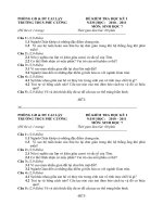
The PC has its own family of microprocessor chips, which were designed by the Intel Corporation. The following figure shows
the Intel 80xx family tree. Your PC may contain an 8086 processor, an 8088 processor (used in the PC/XT), an 80186
processor, an 80286 processor (used in the AT), or even an 80386 processor microprocessor. The first generation of this group
(the 8086) was developed in 1978. The successors of the 8086 were different from the original chip. The 8088 is actually a
step backward because it has the same internal structure and instructions of the 8086, but is slower than the 8086. The reason
for this is the 8086 transfers 16 bits (2 bytes) between memory and the microprocessor simultaneously. The 8088 is slower
since it transfers only 8 bits (1 byte) at a time.
The other microprocessors of this family are improved versions of the 8086. The 80186 provides auxiliary functions. The
80286 has additional registers and extended addressing capabilities. However, the 80286's greatest innovation is protected
mode (see Chapter 33 for more information). DOS doesn't support protected mode.
The 80386 followed the 80286, and marks a great leap forward in performance. However, it's already outdated, and you will
hardly find 386es on the market any more. This processor has advanced protected mode and 32-bit registers. Like protected
mode, DOS doesn't support these registers. The 80386 includes SX and DX versions, which differ in clock frequency and
data bus width. The SX works with a 16-bit data bus, while the DX can transfer an entire 32-bit word at one time.
The 80486 (often simply called "486" ) is no longer the most advanced processor. It remains, however, very popular and sells
in high numbers. It differs from the 80386 because it includes the 80387 math coprocessor, a code cache, and faster processing
of many assembly language instructions. However, the 486 also maintains downward compatibility with the 8086.
The Pentium is today's most advanced processor. The main improvement in the Pentium compared to the 486 is the internal
processing speed. In specific situations, this processor is able to process two sequential commands simultaneously, provided
the second command doesn't depend on the result of the first command.
The name of the processor, Pentium, is also new. Users were expecting the 80586. Intel preferred to break with tradition,
because names such as 8088 or 80586 cannot be protected by copyright. Other chip manufacturers took advantage of this to
sell Intel compatible processors under similar names. Intel decided to take the wind out of the competition's sails and came
up with "Pentium", which is protected by copyright.
1. System Programming Basics
12
No one knows yet whether the Pentium will by followed by the "Hexium", but we can start looking forward to the next
generation of Intel processors, which will be introduced in 1995.
The Intel 80xx
processor family
Performance
1
8
20
50
90
1
2
3
4
11
10
6
5
8
7
9
1
2
3
4
5
6
7
8
9
10
11
8080
8085
8088
8086
80188
80186
80286
80386
80486 DX/33
80486 DX4/100
Pentium/100
74 76 7978 81 82 83 85 89 94
Year
Processor registers
Registers are memory locations within the processor itself instead of in RAM. These registers can be accessed much faster
than RAM. Registers are also specialized memory locations. The processor performs arithmetic and logical operations using
its registers. The processor registers are important for system programming because the flow of information between a
program and the DOS and BIOS functions that call this program occurs through these registers.
From a system programming viewpoint, nothing has changed in registers since the 8086. This is because the BIOS and DOS
were developed in connection with this processor, so they only support this processor's 16-bit registers. The 32-bit registers
of an 80386 and i486 cannot be used in system programming under DOS. We'll discuss only 8088 registers, which apply to
all later chips.
1. System Programming Basics
13
Accumulator
Base
Count
Data
Destination index
Source index
Stack pointer
Base pointer
DI
SI
SP
BP
AX
BX
CX
DX
AH
AL
BH
BL
CH
CL
DH
DL
Data segment
Extra segment
Code segment
Stack segment
DS
ES
CS
SS
15 8 7 0
OD I TS A P C
Z
Instruction
Pointer
IP
Program counter
Flag register
Common registers
Segment registers
8088 registers
also apply to
later processors
All registers are 16 bits (2 bytes) in size. If all 16 bits of a register contain a 1, the result, which is the decimal number 65535,
is the largest number that can be represented within 16 bits. So, a register can contain any value from 0 to 65535 (FFFFH or
1111111111111111b).
Register groupings
As the illustration above shows, registers are divided into four groups: common registers, segment registers, the program
counter and the flag register. The different register assignments are designed to duplicate the way in which a program
processes data, which is the basic task of a microprocessor.
The disk operating system and the routines stored in ROM use the common registers extensively, especially the AX, BX, CX,
and DX registers. The contents of these registers tell DOS what tasks it should perform and which data to use for execution.
These registers are affected mainly by mathematical (addition, subtraction, etc.) and input/output instructions. They are
assigned a special position within the registers of the 8088 because they can be separated into two 8-bit (1 byte) registers. Each
common register usually contains three registers: a single 16-bit register and two smaller 8-bit registers.
Common registers
The common registers are important for calling DOS and BIOS functions and are used to pass parameters to a particular
function that needs these parameters for execution. These registers are also influenced by mathematical operations (addition,
subtraction, etc.), which are the central focus of all software activities at processor level. Registers AX, BX, CX, and DX have
a special position within this set of registers,
because they can be divided into two 8-bit
registers. This means that each of these registers
consists of three registers, one big 16-bit register
and two small 8-bit registers.
Bit 15
AH AL
Bit 15 Bit 8 Bit 7 Bit 0
Bit 0
8088 registers
also apply to
later processors
1. System Programming Basics
14
The small registers have H (high) and L (low) designators. So, the 16-bit AX register may be divided into an 8-bit AH and
an 8-bit AL register. The H and the L register designators occur in such a way the L register contains the lower 8 bits (bit 0
through 7) of the X register, and the H register contains the higher 8 bits (bits 8 through 15) of the X register. The AH register
consists of bits 8-15 and the AL register consists of bits 0-7 of the AX register.
However, the three registers cannot be considered independent of each other. For example, if bit 3 of the AH register is
changed, then the value of bit 11 of the AX register also changes automatically. The values change in both the AH and the
AX registers. The value of the AL register remains constant since it is made of bits 0-7 of the AX register (bit 11 of the AX
register doesn't belong to it). This connection between the AX, the AH, and the AL register is also valid for all other common
registers and can be expressed mathematically.
You can determine the value of the X register from the values of the H and the L registers, and vice versa. To calculate the
value of the X register, multiply the value of the H register by 256 and add the value of the L register.
Example: The value of the CH register is 10 and the value of the CL register is 118. The value of the CX register results
from CH*256+CL, which is 10*256+118 = 2678.
By specifying register CH or CL, you can read or write an 8-bit data item from or to any memory location. Read or write a
16-bit data item from or to a memory location by specifying register CX..
Flag register
Besides common registers, segment registers and the flag register are an important part of system programming. The flag
register communicates between consecutive assembly language instructions by storing the status of mathematical and logical
operations. For example, after using the carry flag to add two 16-bit registers, a program can determine whether the result
is greater than 65,535 and thus present it as a 32-bit number. The sign, zero, and overflow bits perform similar tasks and can
be used after two registers have been compared to establish whether the value of the first register is greater than, less than
or equal to the value of the second register.
Only the carry flag and zero flag are important for system programming from high level languages. Most DOS and BIOS
functions use these flags to indicate errors for insufficient memory or unknown filenames (see Chapter 2 for information on
accessing these flags from high level languages).
Memory addresses
How the processor generates memory addresses is especially important for system programming, because you must
constantly pass buffer addresses to a DOS or BIOS function. In these instances, you must understand what the processor is
doing. The 8088 and its descendants use a complicated procedure. So that you'll understand this procedure, we'll discuss the
origins of the 8086.
One of the design goals of the 8088 was to
provide an instruction set that was superior
to the earlier 8-bit microprocessors (6502,
Z/80, etc.). Another goal was to provide
easy access to more than 64K of memory.
This was important because increasing
processor capabilities allows programmers
to write more complex applications, which
require more memory. The designers of the
8088 processor increased the memory
capacity or address space of the
microprocessor (more than 16 times) to
one megabyte.
CF = Carry Flag
0
123456789101112131415
PF = Parity Flag
AF = Auxilliary Flag
OF
DF
IF
TF
SF
ZF
AF PF CF
ZF = Zero Flag
SF = Sign Flag
TF = Trap Flag
IF = Interrupt Flag
DF = Direction Flag
OF = Overflow Flag
Flags of the flag register
1. System Programming Basics
15
Address register
The number of memory locations that a processor can access depends on the width of the address register. Since every memory
location is accessed by specifying a unique number or address, the maximum value contained in the address register
determines the address space. Earlier microprocessors used a 16-bit address register, which enables users to access addresses
from 0 to 65535. This corresponds to the 64K memory capacity of these processors. To address one megabyte of memory,
the address register must be at least 20 bits wide. At the time the 8088 was developed, it was impossible to use a 20-bit address
register, so the designers used an alternate way to achieve the 20-bit width. The contents of two different 16-bit numbers are
used to form the 20-bit address.
Segment register
One of these 16-bit numbers is contained in a segment register. The 8088 has four segment registers. The second number is
contained in another register or in a memory location. To form a 20-bit number, the contents of the segment register are shifted
left by 4 bits (thereby multiplying the value by 16) and the second number is added to the first.
0000
Bit
012341415 13
. . . . . .
Bit
012341415 13
. . . . . .
Bit
012341819 17
. . . . . .
Segment address
Offset address
Physical address
Logical address
16 Bit
16 Bit
20 Bit
Structure of
memory address
from segment
and offset
addresses
Segment and offset addresses
These addresses are the segment address and the offset address. The segment address, which is formed by a segment register,
indicates the start of a segment of memory. When the address is created, the offset address is added to the segment address.
The offset address indicates the number of the memory location within the segment whose beginning was defined by the
segment register. Since the offset address cannot be larger than 16 bits, a segment cannot be larger than 65,535 bytes (64K).
Let's assume the offset address is always 0 and the segment address is also 0 at first. In this case, you receive the address of
memory location 0. If the segment address is increased to 1, you receive the address of memory location 1 instead of memory
location 16. This happens because the segment address is multiplied by 16 when addresses are formed.
If you continue incrementing the segment address, you'll receive memory addresses of 32, 48, 64, etc., if the offset address
continues to be 0. According to this principle, the maximum memory address is 1 megabyte when the segment address reaches
65535 (FFFFH), which is its maximum value. However, if you keep the segment address constant and increment the offset
address instead, the segment address will quickly become the base address for a memory segment from which you can reach
a total of 65,536 different memory locations. Each memory segment contains 64K. The offset address represents the distance
of the desired memory locations from the beginning of the segment.
Although the individual memory segments are only 16 bytes apart, they contain 64K. So they obviously overlap in memory.
Because of this, a memory address, such as 130, can be represented in various ways by using segment and offset addresses.
1. System Programming Basics
16
Structure of
memory address
from segment
and offset
addresses
26000H
25FFFH
25FFEH
17105H
17104H
17103H
16000H
15FFFH
1
0
Segment
Incrementing memory address
16001H
Offset
Segment address = 1600H
Offset address = 1104H
For example, you could specify 0 as the segment address and 130 as the offset address. It's also possible to specify 1 as the
segment address and 114 as the offset address or 2 as the segment address and 98 as the offset address, etc. These overlapping
segments are easy to use. When you specify an address you can choose the combination of segment address and offset address
yourself. You must obtain the desired address by multiplying the segment address by 16 and adding the offset address to it;
everything else is unimportant.
A segment cannot start at every one of the million or so memory locations. Multiplying the segment register by 16 always
produces a segment address that is divisible by 16 (i.e., it's not possible for a segment to begin at memory location 22).
Segmented address
The segmented address results from the combined segment and offset addresses. This segmented address specifies the exact
number of the memory location that should be accessed. Unlike the segmented address, the segment and the offset addresses
are relative addresses or relative offsets.
Combining the segment and offset addresses requires special address notation to indicate a memory location's address. This
notation consists of the segment address, in four-digit hexadecimal format, followed by a colon, and the offset address in four-
digit hexadecimal format. For example, in this notation a memory location with a segment address of 2000H and an offset
address of AF3H would appear as "2000:0AF3". Because of this notation, you can omit the H suffix from hexadecimal
numbers.
The segment register for program execution
The 8088 contains four important segment registers for the execution of an assembly language program. These registers
contain the basic structure of any program, which consists of a set of instructions (code). Variables and data items are also
processed by the program. A structured program keeps the code and data separate from each other while they reside in
memory. Assigning code and data their own segments conveniently separates them. These segment registers are as follows:
CS The CS (Code Segment) register uses the IP (Instruction Pointer) register as the offset address. Then it determines the
address at which the next assembly language instruction is located. The IP is also called the Program Counter. When
the processor executes the current instruction, the IP register is automatically incremented to point to the next assembly
language instruction. This ensures the instructions are executed in the proper order.
DS Like the CS register, the DS (Data Segment) register contains the segment address of the data the program accesses
(writing or reading data to or from memory). The offset address is added to the content of the DS register and may be
contained in another register or may be contained as part of the current instruction.
1. System Programming Basics
17
SS The SS (Stack Segment) register specifies the starting address of the stack. The stack acts as temporary storage space
for some assembly language programs. It allows fast storage and retrieval of data for various instructions. For example,
when the CALL instruction is executed, the processor places the return address on the stack. The SS register and either
the SP or BP registers form the address that is pushed onto the stack.
When accessing the stack, address generation occurs from the SS register in conjunction with the SP or BP register.
ES The last segment register is the ES (Extra Segment) register. It's used by some assembly language instructions to
address more than 64K of data or to transfer data between two different segments of memory.
Copying of
Memory Areas
using DS and
ES Segment
Addresses
64K
64K
DS
ES
With the help of the ES register, however, it's possible to leave the DS register on the memory segment of the source area
while referencing the target area using the ES memory segment. The 8088 and its descendants even have assembly language
instructions that can copy an entire buffer by assuming, before their execution, the segment address of the start area has been
loaded into the DS register and the segment address of the target area has been loaded into the ES register. To copy the
instructions also need the start of both areas within their memory segments. They expect the start of the source area in the
SI register and the start of the target area in the DI register. Expressed in the notation introduced earlier, these instructions
copy data from DS:SI to ES:DI.
Overlapping segments
As the illustration on the following page shows, two segment registers can specify areas of memory that overlap or are
completely different from each other. Usually a program doesn't require a full 64K segment for storing code or data. So, you
can conserve memory by overlapping the segments. For example, you can store data, which immediately follows the program
code, by setting the DS and CS registers accordingly.
NEAR and FAR pointers
The numbers we've been calling memory addresses are called pointers in high level languages. A pointer in the Pascal or C
language receives the addresses of the objects referenced by the pointers. If these addresses change location in memory, the
pointers also change. The two types of pointers are NEAR pointers and FAR pointers. NEAR pointers specify the offset
address of an object and are only 16 bits wide. Memory cannot be accessed without a segment address. So the compiler
prepares the segment address, which it automatically loads, to the appropriate segment register when accessing the object.
Because of this, NEAR pointer access is only possible for variables within the 64K segment created by the compiler.
FAR pointers consist of a segment address and an offset address, so they are saved as two words. The low word receives the
offset address and the high word receives the segment address. In Turbo Pascal, pointers are VAR, while in C their type
depends on the memory model (see Chapter 2 for more information about pointers).
Data types and their storage
Bytes and words aren't the only data types you'll encounter in system programming. You'll frequently encounter DWORDs
(double words), which are used when the 16 bits of one word aren't enough to store a number. For example, this applies to
the internal BIOS clock, which exceeds the 16-bit level of 65535 after a little more than ten hours.
1. System Programming Basics
18
Incrementing memory address
ES:FFFF
ES:0000
SS:FFFF
DS:FFFF
SS:0000
DS:0000
CS:FFFF
CS:0000
ES:FFFF
ES:0000
CS:FFFF
CS:0000
SS:FFFF
SS:0000
DS:FFFF
DS:0000
Non-overlapping
(left) and
overlapping
(right) segments
The members of the Intel 80xxx family place DWORDs in memory so the low word (bits 0 to 15) precedes the high word
(bits 16 to 31). This procedure is referred to as the little endian format. This is different than the big endian format, which
reverses the order and is used by processors of the Motorola 68000 family (e.g., the Apple Macintosh). The little endian
principle also applies to word storage, in which the low word is placed in front of the high word. Even with QWORDs (4
words), which are used by the numerical coprocessor, the low-order DWORD (bits 0 to 31) is stored in front of the high-order
DWORD (bits 32 to 63). Then, within these two DWORDs, the high word is placed in front of the low word, etc. The following
illustration demonstrates this principle:
Storing different
data types in
little endian
format
Offset
Word
Low byte
0
High byte
1
DWord
Low word
0
High word
2
Offset
0
Segment
2
FAR-PTR
Low dword
0
QWord
4
High dword
1. System Programming Basics
19
Ports
P
orts represent interfaces between the processor and the other system hardware. A port is similar to an 8-bit wide data input
or output connected to a specific piece of hardware. It has an assigned address with values ranging from 0 to 65,535. The
processor uses the data bus and address bus to communicate with the ports. If the processor needs to access a port, it transmits
a port control signal. This signal instructs the other hardware the processor wants to access a port instead of RAM.
Although ports have addresses that are also assigned to memory locations in RAM, these addresses aren't related to the
memory locations. The port address is placed on the lowest 16 bits of the address bus. This instructs the system to transfer
the eight bits of information on the data bus to the proper port. The hardware connected with this port receives the data and
responds accordingly. The 80(x)xx processor series has two instructions that control this process from within a program. The
IN instruction sends data from the processor to a port and the OUT instruction transfers data from a port into the processor.
Each hardware device is responsible for an area of port addresses. Therefore, conflicts between expansion boards that allocate
the same port address area often occur. So, most expansion boards have DIP switches for setting the port address to which
the board will respond. This helps avoid conflicts with other boards.
The system can set the port address of a certain hardware device. Since this address isn't a constant value, port addressing
is similar for the PC, XT, and AT. Although there are only a few differences between the PC and XT, there are many differences
between the PC and AT. The following table shows the port addresses of individual chips in each system.
Component PC/XT AT
DMA controller (8237A-5) 000-00F 000-01F
Interrupt controller (8259A) 020-021 020-03F
Timer 040-043 040-05F
Programmable Peripheral Interface (PPI 8255A-5) 060-063 none
Keyboard (8042) none 060-06F
Realtime clock (MC146818) none 070-07F
DMA page register 080-083 080-09F
Interrupt controller 2 (8259A) none 0A0-0BF
DMA controller 2 (8237A-5) none 0C0-0DF
Math coprocessor none 0F0-0F1
Math coprocessor none 0F8-0FF
Hard drive controller 320-32F 1F0-1F8
Game port (joysticks) 200-20F 200-207
Expansion unit 210-217 none
Interface for second parallel printer none 278-27F
Second serial interface 2F8-2FF 2F8-2FF
Prototype card 300-31F 300-31F
Network card none 360-36F
Interface for first parallel printer 378-37F 378-37F
Monochrome Display Adapter and parallel interface 3B0-3BE 3B0-3BF
Color/Graphics Adapter 3D0-3DF 3D0-3DF
Disk controller 3F0-3F7 3F0-3F7
First serial interface 3F8-3FF 3F8-3FF
1. System Programming Basics
20
Interrupts
I
n the "Basics of PC Hardware" section in this chapter we explained that interrupts are mechanisms that force the
processor to briefly interrupt the current program and execute an interrupt handler. However, this is only one aspect of
interrupts. They are also important for controlling the hardware, and act as the main form of communication between a
program and the BIOS and DOS functions.
Software interrupts
Software interrupts call a program, with a special assembly language instruction, to execute a DOS, BIOS, or EMS function.
The program execution isn't really interrupted; the processor views the called function as a subroutine. After the subroutine
executes, the processor continues with the calling program.
To call a DOS or BIOS function using a software interrupt, only the number of the interrupt, from which the routine can be
reached, is needed. The caller doesn't even need to know the address of the routine in memory. These routines are standardized.
So, regardless of your DOS version, you know that by calling interrupt 21H you can access DOS functions. The processor
calls the interrupt handler using the interrupt vector table, from which the processor takes the addresses of the desired function.
The processor uses the interrupt number as an index to this table. The table is set during system bootup so the various interrupt
vectors point to the ROM-BIOS.
This illustrates the advantage of using interrupts. A PC manufacturer who wants to produce an IBM compatible PC cannot
copy the entire ROM-BIOS from IBM. However, the manufacturer is allowed to implement the same functions in its ROM-
BIOS, even if the BIOS functions are coded differently from within. So, the BIOS functions are called using the same
interrupts that IBM uses and expect parameters in the same processor registers. But the routines that provide the functions
are organized differently than the routines provided by IBM. Other advantages of using interrupts are described in Chapter
2. First, let's look at the interrupt vector table, which represents the key to calling the interrupts.
Interrupt vector table
So far we've discussed a single interrupt and a single interrupt routine. Actually, the 8088 has 256 possible interrupts numbered
from 0 to 255. Each interrupt has an associated interrupt routine to handle the particular condition. To organize the 256
interrupts, the starting addresses of the corresponding interrupt routines are arranged in the interrupt vector table.
When an interrupt occurs, the processor automatically retrieves the starting address of the interrupt routine from the interrupt
vector table. The starting address of each interrupt routine is specified in the table in terms of the offset address and segment
address. Both addresses are 16 bits (2 bytes) wide. So each table entry occupies 4 bytes. The total length of the table is 256x4
or 1024 bytes (1K). Because the interrupt vector table is in RAM, any program can change it. However, TSR programs and
device drivers use the table the most (see Chapter 35).
1. System Programming Basics
21
Starting
addresses of the
interrupt
routines are
arranged in the
interrupt vector
table
IP
CS
IP
CS
IP
CS
CS
IP
IP
CS
0000:003FE
0000:003FC
0000:000E
0000:000C
0000:000A
0000:0008
0000:0006
0000:0004
0000:0002
0000:0000
255
3
2
1
0
Incrementing memory address
Purpose
Address
Interrupt
number
Free
Break point
NMI
Single-step
Division by 0
The following table shows the addresses of the various interrupt vectors, as well as the utilities from which they can be reached.
This layout applies to all PCs and is an essential component of the PC standard. A program that uses these interrupts will find
these utilities on all PCs. Most of these interrupts and their functions are mentioned throughout this book.
Many of these interrupt vectors are only allocated when the corresponding hardware has also been installed. For example,
this applies to interrupt 33H (mouse driver functions) and interrupt 5CH (network functions). The term "reserved" indicates
the interrupt is called by a certain system component (usually DOS), but the interrupt's use was never documented. In other
words, we know who is using it, but we don't know why.
Summary Of Interrupts
No.* Address* Purpose
00 000 - 003 Processor: Division by zero
01 004 - 007 Processor: Single step
02 008 - 00B Processor: NMI (Error in RAM chip)
03 00C - 00F Processor: Breakpoint reached
04 010 - 013 Processor: Numeric overflow
05 014 - 017 Hardcopy
06 018 - 01B Unknown instruction (80286 only)
07 01D - 01F Reserved
08 020 - 023 IRQ0: Timer (Call 18.2 times/sec.)
09 024 - 027 IRQ1: Keyboard
0A 028 - 02B IRQ2: 2nd 8259 (AT only)
0B 02C - 02F IRQ3: Serial port 2
0C 030 - 033 IRQ4: Serial port 1
0D 034 - 037 IRQ5: Hard drive
1. System Programming Basics
22
Summary Of Interrupts
No.* Address* Purpose
0E 038 - 03B IRQ6: Diskette
0F 03C - 03F IRQ7: Printer
10 040 - 043 BIOS: Video functions
11 044 - 047 BIOS: Determine configuration
12 048 - 04B BIOS: Determine RAM memory size
13 04C - 04F BIOS: Diskette/hard drive functions
14 050 - 053 BIOS: Access to serial port
15 054 - 057 BIOS: Cassettes/extended function
16 058 - 05B BIOS: Keyboard inquiry
17 05C - 05F BIOS: Access to parallel printer
18 060 - 063 Call ROM BASIC
19 064 - 067 BIOS: Boot system (Ctrl+Alt+Del)
1A 068 - 06B BIOS: Prompt time/date
1B 06C - 06F Break key (not Ctrl-C) pressed
1C 070 - 073 Called after each INT 08
1D 074 - 077 Address of video parameter table
1E 078 - 07B Address of diskette parameter table
1F 07C - 07F Address of character bit pattern
20 080 - 083 DOS: Quit program
21 084 - 087 DOS: Call DOS function
22 088 - 08B Address of DOS quit program routine
23 08C - 08F Address of DOS Ctrl-Break routine
24 090 - 093 Address of DOS error routine
25 094 - 097 DOS: Read diskette/hard drive
26 098 - 09B DOS: Write diskette/hard drive
27 09C - 09F DOS: Quit program, stay resident
28 0A0 - 0A3 DOS: DOS is unoccupied
29-2E 0A4 - 0BB DOS: Reserved
2F 0BC - 0BF DOS: Multiplexer
30-32 0C0 - 0CB DOS: Reserved
33 0CC - 0CF Mouse driver functions
34-40 0D0 - 0FF DOS: Reserved
41 104 - 107 Address of hard drive table 1
42-45 108 - 117 Reserved
46 118 - 11B Address of hard drive table 2
47-49 11C - 127 Can be used by programs
1. System Programming Basics
23
Summary Of Interrupts
No.* Address* Purpose
4A 128 - 12B Alarm time reached (AT only)
4B-5B 12C - 16F Free: can be used by programs
5C 170 - 173 NETBIOS functions
5D-66 174 - 19B Free: can be used by programs
67 19C - 19F EMS memory manager functions
68-6F 1A0 - 1BF Free: can be used by programs
70 1C0 - 1C3 IRQ08: Realtime clock (AT only)
71 1C4 - 1C7 IRQ09: (AT only)
72 1C8 - 1CB IRQ10: (AT only)
73 1CC - 1CF IRQ11: (AT only)
74 1D0 - 1D3 IRQ12: (AT only)
75 1D4 - 1D7 IRQ13: 80287 NMI (AT only)
76 1D8 - 1DB IRQ14: Hard drive (AT only)
77 1DC - 1DF IRQ15: (AT only)
78-7F 1E0 - 1FF Reserved
80-F0 200 - 3C3 Used within the BASIC interpreter
F1-FF 3C4 - 3CF Reserved
*= All addresses and numbers in hexadecimal notation
Hardware interrupts
Hardware interrupts are produced by various hardware components and passed, by the interrupt controller, to the processor.
In this section we'll explain the steps involved in this process and the differences between PC/XTs and ATs.
PC/XT hardware interrupts
Hardware interrupts 8 to 15 are called by the interrupt controller. Up to eight devices (interrupt sources) can be connected
to the PC interrupt controller using interrupt lines IRQ0 to IRQ7. The device on line IRQ0 has the highest priority. The device
connected with IRQ7 has the lowest priority. For example, if two interrupt requests arrive on lines IRQ3 and IRQ5, IRQ3
is addressed first. The number of the interrupt results from adding 8 to the IRQ number (in this case, it's interrupt 11).
Disabling hardware interrupts
It's possible for a program to prevent the execution of hardware interrupts. This is useful when program execution shouldn't
be interrupted. The processor will release a hardware interrupt, upon request from the interrupt controller, only if the interrupt
flag is set in the processor's flag register. If the software has cleared the flag, the interrupt controller won't receive the requested
interrupt.
You can also block single interrupts by programming the interrupt mask register in the interrupt controller.
1. System Programming Basics
24
76543210
Bit
Interrupt controller
at port 20H
Decreasing priority
Timer
Keyboard
2nd serial interface
Diskette
Parallel interface
PC
1st serial interface
PC interrupt
requests and
priorities
76543210
Bit
Interrupt controller
at port 20H
Timer
Keyboard
Diskette
XT
Hard drive
Decreasing priority
2nd serial interface
Parallel interface
1st serial interface
XT interrupt
requests and
priorities
AT hardware interrupts
ATs have two 8259 interrupt controllers, which provide 16 interrupt sources. The eight additional interrupts are labeled IRQ08
to IRQ15. When an interrupt request addresses the second interrupt controller, it emulates an IRQ2 from the first interrupt
controller. All the interrupt requests of the second interrupt controller are assigned a higher priority than lines IRQ4 to IRQ7
of the first interrupt controller.
If a request for IRQ2 is granted, the interrupt handler of interrupt 10 is executed. This interrupt handler first reads some of
the registers of the second interrupt controller to determine the number of the IRQ. Based on the IRQ number, one of interrupts
70H to 77H is called as a software interrupt. It doesn't matter the call was actually initiated by the hardware because the device
is waiting for execution of "its" interrupt handler. However, as a result of this procedure, the IRQ2 is unavailable to the first
interrupt controller. So 15 interrupt sources are supported instead of 16.