im0019092 safety relay sick
Bạn đang xem bản rút gọn của tài liệu. Xem và tải ngay bản đầy đủ của tài liệu tại đây (7.46 MB, 124 trang )
OPERATING INSTRUCTIONS
Flexi Classic
Modular Safety Controller
en
Operating instructions
Flexi Classic
This document is protected by the law of copyright, whereby all rights established therein remain with the
company SICK AG. Reproduction of this document or parts of this document is only permissible within the limits
of the legal determination of Copyright Law. Alteration or abridgement of the document is not permitted without
the explicit written approval of the company SICK AG.
2
© SICK AG • Industrial Safety Systems • Germany • All rights reserved
8011509/YJD4/2015-04-21
Subject to change without notice
Operating instructions
Contents
Flexi Classic
Contents
8011509/YJD4/2015-04-21
Subject to change without notice
1
About this document.........................................................................................................7
Function of this document....................................................................................7
1.1
1.2
Target group ..........................................................................................................7
1.3
Information depth .................................................................................................7
1.4
Scope .....................................................................................................................8
1.5
Abbreviations.........................................................................................................8
1.6
Symbols used ........................................................................................................8
2
On safety...........................................................................................................................12
2.1
Qualified safety personnel..................................................................................12
2.2
Applications of the device...................................................................................12
2.3
Correct use ..........................................................................................................13
2.4
General safety notes and protective measures ................................................13
2.5
Environmental protection ...................................................................................15
2.5.1
Disposal .............................................................................................15
2.5.2
Separation of materials ....................................................................15
3
Product description.........................................................................................................16
3.1
Special features ..................................................................................................16
3.2
Structure..............................................................................................................17
3.2.1
UE410-MU main module ..................................................................17
3.2.2
UE410-GU main module ...................................................................18
3.2.3
UE410-8DI input extension module.................................................19
3.2.4
UE410-XU input/output extension ...................................................19
3.2.5
UE410-2RO/UE410-4RO output modules.......................................19
3.2.6
Gateways ...........................................................................................19
3.2.7
Module overview, adjustments and facilities for connecting
sensors ..............................................................................................20
3.3
UE410-MU main module ....................................................................................23
3.3.1
Controls and status indicators .........................................................25
3.3.2
Terminal assignment ........................................................................26
3.3.3
Outputs ..............................................................................................27
3.4
UE410-GU main module .....................................................................................28
3.4.1
Controls and status indicators .........................................................29
3.4.2
Terminal assignment ........................................................................30
3.4.3
Global emergency stop with the UE410-GU ....................................30
3.4.4
Local emergency stop on the UE410-GU.........................................32
3.4.5
Inputs .................................................................................................32
3.4.6
Outputs ..............................................................................................33
3.4.7
Connection of a UE410-8DI..............................................................33
3.4.8
Power-up delay and response time of the UE410-GU.....................33
3.4.9
Diagnostics and troubleshooting for the UE410-GU .......................34
3.5
UE410-XU module...............................................................................................36
3.5.1
Controls and status indicators .........................................................36
â SICK AG ã Industrial Safety Systems • Germany • All rights reserved
3
Contents
Operating instructions
Flexi Classic
3.6
3.7
3.8
3.9
4
4
UE410-MU/UE410-XU programs ....................................................................... 37
Program 1 ......................................................................................... 38
3.6.1
3.6.2
Program 2 ......................................................................................... 39
3.6.3
Programs 3.1 and 3.2 ...................................................................... 40
3.6.4
Program 4 ......................................................................................... 41
3.6.5
Programs 5.1 and 5.2 ...................................................................... 42
3.6.6
Program 6 ......................................................................................... 43
3.6.7
Program 7 ......................................................................................... 44
3.6.8
Program 8 ......................................................................................... 45
3.6.9
Program 9 ......................................................................................... 46
3.6.10
Connection of sensors to the UE410-MU/UE410-XU ..................... 47
UE410-GU programs .......................................................................................... 50
UE410-8DI input extension module .................................................................. 52
3.8.1
AND link............................................................................................. 53
3.8.2
OR link ............................................................................................... 54
3.8.3
Bypass ............................................................................................... 54
3.8.4
Reciprocal assignment — Mirror mode............................................ 55
3.8.5
Connection of sensors to the UE410-8DI........................................ 55
3.8.6
Controls and status indicators......................................................... 57
3.8.7
Inputs and outputs ........................................................................... 58
UE410-2RO/UE410-4RO output modules ........................................................ 58
3.9.1
Output module UE410-2RO ............................................................. 58
3.9.2
Output module UE410-4RO ............................................................. 59
3.9.3
Controls and status indicators......................................................... 60
3.9.4
UE410-2RO inputs and outputs....................................................... 60
3.9.5
UE410-4RO inputs and outputs....................................................... 60
Special applications and functions............................................................................... 61
4.1
RE300 magnetic safety switch .......................................................................... 62
4.2
IN4000 inductive safety switch ......................................................................... 63
4.3
Testable single-beam photoelectric safety switches ........................................ 64
4.4
Two-hand operation/jog mode........................................................................... 67
4.5
OR function ......................................................................................................... 68
4.6
Muting function................................................................................................... 69
4.6.1
Muting with two sensors .................................................................. 70
4.6.2
Muting cycle ...................................................................................... 70
4.6.3
Muting sensors ................................................................................. 70
4.7
Placement of muting sensors ............................................................................ 71
4.7.1
Muting with two sensors (a sensor pair), crossed placement........ 72
4.7.2
4-sensor muting, sequential layout ................................................. 73
4.7.3
Muting with UE410-MU/UE410-XU ................................................. 73
4.8
SICK muting sensors .......................................................................................... 74
4.9
Bypass ................................................................................................................. 75
4.10 Connecting S1, S2, S3 ....................................................................................... 76
4.10.1
Operation with restart interlock ....................................................... 76
4.10.2
Operation without restart interlock.................................................. 76
4.10.3
Operation with external device monitoring (EDM) .......................... 76
4.11 Retriggering of the delayed OSSDs.................................................................... 77
4.12 Grouping of subsystems..................................................................................... 79
4.13 ENABLE input ...................................................................................................... 80
â SICK AG ã Industrial Safety Systems • Germany • All rights reserved
8011509/YJD4/2015-04-21
Subject to change without notice
Operating instructions
Contents
Flexi Classic
5
Mounting/dismantling....................................................................................................81
5.1
Steps for mounting the modules........................................................................81
5.2
Steps for dismantling the modules ....................................................................82
5.3
Removing the anti-manipulation cover ..............................................................83
6
Electrical installation......................................................................................................84
7
Application examples and connection diagrams ........................................................86
7.1
L21 on the UE410-MU/XU..................................................................................86
7.2
Emergency stop on the UE410-MU/XU..............................................................86
7.3
RE300 on the UE410-MU/XU.............................................................................87
7.4
Two-hand IIIC on the UE410-MU/XU ..................................................................87
7.5
C2000 and emergency stop on the UE410-MU/XU, two hazardous
areas ....................................................................................................................88
7.6
i11 on the UE410-MU/XU, two independent hazardous areas........................88
7.7
IN4000 on the UE410-MU/XU ...........................................................................89
7.8
C4000 on the UE410-MU/XU, 2-sensor muting................................................89
7.9
Global emergency stop with two UE410-GU......................................................90
8
Commissioning ................................................................................................................91
8.1
Validation of the application...............................................................................91
8.2
Test notes ............................................................................................................92
8.2.1
Tests before the first commissioning...............................................92
8.2.2
Regular testing ..................................................................................92
8.2.3
Regular inspection of the protective device by qualified
safety personnel................................................................................92
9
Configuration ...................................................................................................................93
9.1
Accepting the system configuration...................................................................93
10 Diagnostics ......................................................................................................................94
10.1 In the event of faults or errors............................................................................94
10.2 Replacement of a module ..................................................................................94
10.3 SICK support........................................................................................................95
10.4 Error indications of the ERR error LED...............................................................95
10.5 Anti-manipulation measures ..............................................................................96
11 Technical specifications.................................................................................................97
11.1 Data sheet ...........................................................................................................97
11.1.1
UE410-MU/UE410-XU modules .......................................................97
11.1.2
UE410-GU module ......................................................................... 102
11.1.3
UE410-8DI input extension module.............................................. 106
11.1.4
UE410-2RO/UE410-4RO output modules.................................... 108
11.2 Dimensional drawings ..................................................................................... 112
11.2.1
UE410-MU and UE410-GU main modules.................................... 112
11.2.2
UE410-XU, UE410-8DI, UE410-2RO, UE410-4RO, UE410PRO, UE410-DEV, UE410-CAN modules....................................... 112
8011509/YJD4/2015-04-21
Subject to change without notice
â SICK AG ã Industrial Safety Systems • Germany • All rights reserved
5
Contents
Operating instructions
Flexi Classic
12 Ordering information ....................................................................................................113
12.1 Available modules ............................................................................................113
12.2 Accessories/spare parts ..................................................................................116
12.2.1
Single-beam photoelectric safety switches...................................116
12.2.2
Non-contact safety switches ..........................................................117
12.2.3
Safety light curtains and multiple light beam safety devices.......118
12.2.4
Safety laser scanners and safety camera system ........................118
12.2.5
Muting lamps and cables...............................................................118
12.2.6
Anti-manipulation cover .................................................................118
13 Annex..............................................................................................................................119
13.1 EU declaration of conformity............................................................................119
13.2 Manufacturer’s checklist .................................................................................119
13.3 List of tables .....................................................................................................120
13.4 List of illustrations ............................................................................................121
6
â SICK AG ã Industrial Safety Systems • Germany • All rights reserved
8011509/YJD4/2015-04-21
Subject to change without notice
About this document
Operating instructions
Chapter 1
Flexi Classic
1
About this document
Please read this chapter carefully before working with this documentation and the Flexi
Classic modular safety controller.
1.1
Function of this document
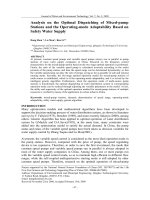
These operating instructions are designed to address the technical personnel of the machine manufacturer or the machine operator in regards to safe mounting, configuration,
electrical installation, commissioning, operation and maintenance of the Flexi Classic
modular safety controller.
These operating instructions do not provide instructions for operating machines on which
the safety controller is, or will be, integrated. Information on this is to be found in the appropriate operating instructions for the machine.
1.2
Target group
These operating instructions are addressed to planning engineers, machine designers and
operators of plants and systems which are to be protected by a Flexi Classic modular safety controller. They are also addressed to people who integrate the Flexi Classic modular
safety controller into a machine, initialise its use, or who are in charge of servicing and
maintaining the device.
1.3
Information depth
These operating instructions contain the following information on the Flexi Classic modular
safety controller:
electrical installation
fault, error diagnosis and
troubleshooting
commissioning and configuration
part numbers
care and maintenance
conformity and approval
mounting
Planning and using SICK protective devices also require specific technical skills which are
not detailed in this documentation.
When operating the Flexi Classic modular safety controller, the national, local and statutory rules and regulations must be observed.
General information on accident prevention using opto-electronic protective devices can
be found in the competence brochure “Guidelines Safe Machinery”.
Note
We also refer you to the homepage on the Internet at www.sens-control.com.
Here you will find information on:
product and application animations
configuration aid
these operating instructions in different languages for viewing and printing
8011509/YJD4/2015-04-21
Subject to change without notice
â SICK AG ã Industrial Safety Systems • Germany • All rights reserved
7
About this document
Chapter 1
Operating instructions
Flexi Classic
1.4
Scope
These operating instructions are original operating instructions.
These operating instructions apply to all Flexi Classic safety controller modules with the
following entry in the field Operating Instructions on the type label: “EL01” or higher. Take
into account the respectively applicable operating instructions (refer to the type label entry
on the modules).
1.5
EDM
External device monitoring
ESPE
Electro-sensitive protective equipment (e.g. C4000)
OSSD
Output signal switching device
PLC
Programmable logic controller
SIL
SILCL
Safety Integrity Level
SIL claim limit
1.6
Note
,
Abbreviations
,
Take action …
Symbols used
Refer to notes for special features of the device.
LED symbols describe the state of a diagnostics LED. Examples:
The LED is illuminated constantly.
The LED is flashing.
The LED is off.
Instructions for taking action are shown by an arrow. Read carefully and follow the
instructions for action.
Warning!
WARNING
A warning notice indicates an actual or potential risk or health hazard. They are designed
to help you to prevent accidents.
Read carefully and follow the warning notices!
8
â SICK AG ã Industrial Safety Systems • Germany • All rights reserved
8011509/YJD4/2015-04-21
Subject to change without notice
Operating instructions
About this document
Chapter 1
Flexi Classic
Tab. 1: Sensor symbols
Symbol
Sensors
Electro-mechanical safety switches
Emergency stop button
Electro-sensitive protective equipment (ESPE)
Sensors that can be tested (e.g. photoelectric switches)
Inductive safety sensors (e.g. IN4000)
Two-hand operating panel (IIIA)
Two-hand operating panel (IIIC)
Jog mode via two-hand operating panel (IIIA) (time limit 5 s)
Muting lamp and Reset required lamp (not monitored)
Lamp permanently ON: Muting active
Lamp flashing 1 Hz: Reset required
Pressure sensitive mats (4-wire system)
Reset button
Flexi Loop
8011509/YJD4/2015-04-21
Subject to change without notice
© SICK AG • Industrial Safety Systems • Germany • All rights reserved
9
About this document
Chapter 1
Operating instructions
Flexi Classic
Tab. 2: Module function
symbols
Symbol
Module functions
Bypass function with electro-mechanical dual-channel equivalent switch
(e.g. enabling switch),
Bypass function limited to 60 s
Muting station with two inputs for muting sensors
Retriggering
N
Monitored semiconductor output
Q1
Off delay
ENABLE (EN)
EN
10
â SICK AG ã Industrial Safety Systems • Germany • All rights reserved
8011509/YJD4/2015-04-21
Subject to change without notice
Operating instructions
About this document
Chapter 1
Flexi Classic
Tab. 3: Input assignment
symbols
Symbol
Input assignment
Single-channel N/C contact
Single-channel N/C contact, cross-circuit detecting
Single-channel N/C contact at two inputs
Dual-channel N/C contact, equivalent, cross-circuit detecting, with
monitoring of synchronisation (1500 ms)
Dual-channel N/C contact, equivalent, cross-circuit detecting
Dual-channel N/C contact, equivalent
Dual-channel N/C / N/O contact, complementary, cross-circuit detecting
Dual-channel N/C / N/O contact, complementary, cross-circuit detecting,
with monitoring of synchronisation (1500 ms), (e.g. magnetically coded
switch RE300)
Dual-channel semiconductor input, monitored (ESPE)
Single-channel N/C contact/semiconductor input (e.g. sensors that can be
tested)
Switching mats, pressure-sensitive (4-wire system)
Tab. 4: Logic symbols
Symbol
Logic
OR link
&
8011509/YJD4/2015-04-21
Subject to change without notice
AND link
â SICK AG ã Industrial Safety Systems • Germany • All rights reserved
11
On safety
Chapter 2
Operating instructions
Flexi Classic
2
On safety
This chapter deals with your own safety and the safety of the equipment operators.
Please read this chapter carefully before working with the Flexi Classic modular safety
controller or with the machine protected by the Flexi Classic modular safety controller.
2.1
Qualified safety personnel
The Flexi Classic modular safety controller must be mounted, commissioned and serviced
only by qualified safety personnel.
Qualified safety personnel are defined as persons who …
have undergone the appropriate technical training
and
who have been instructed by the responsible machine operator in the operation of the
machine and the current valid safety guidelines
and
have access to the operating instructions of the Flexi Classic and those of the particular
modules and have read and familiarised themselves with them
and
have access to the operating instructions for the protective devices (e.g. C4000)
connected to the safety controller and have read and familiarised themselves with
them.
2.2
Applications of the device
The Flexi Classic modular safety controller is a configurable control system for safety
applications.
The category in accordance with EN ISO 13 849L1 or the SIL in accordance with IEC 61 508
and the SILCL in accordance with EN 62 061 depend on the external circuit, the realisation
of the wiring, the choice of the sensors and their location at the machine.
The device corresponds to up to category 4 in accordance with EN ISO 13 849L1; applications can reach up to SIL3 in accordance with IEC 61 508, up to SILCL3 in accordance
with EN 62 061 or PL e in accordance with EN ISO 13 849L1. The emergency stop function
in the device corresponds to stop category 0 or 1 in accordance with EN 60 204L1.
In order to reach the SIL3 safety level (see chapter 11 “Technical specifications” on
page 97) in accordance with IEC 61 508, the following test must be made at least every
365 days:
The Flexi Classic system must be powered down.
The Flexi Classic system must be powered up.
All safety functions of the connected safety sensors must be verified.
The type of safety sensors as well as the method of wiring must be chosen according to
the category which is to be achieved.
Opto-electronic and tactile safety sensors (e.g. light curtains, laser scanners, safety switches, sensors, emergency stop pushbuttons) are connected to the modular safety controller
and are linked logically. The corresponding actuators of the machines or systems can be
switched off safely via the switching outputs of the safety controller.
The Flexi Classic safety controller has been tested in accordance with UL 508.
12
â SICK AG ã Industrial Safety Systems ã Germany • All rights reserved
8011509/YJD4/2015-04-21
Subject to change without notice
Operating instructions
On safety
Chapter 2
Flexi Classic
2.3
Correct use
The Flexi Classic modular safety controller may only be used as intended in section 2.2
“Applications of the device”. It may only be used by specialist personnel and only at the
machine at which it was mounted and initially commissioned by qualified safety personnel
in accordance with these operating instructions.
If the device is used for any other purposes or modified in any way — also during mounting
and installation — any warranty claim against SICK AG shall become void.
2.4
General safety notes and protective measures
Observe the safety notes and protective measures!
WARNING
Please observe the following items in order to ensure correct use of the Flexi Classic
modular safety controller.
When mounting, installing and using the Flexi Classic, observe the standards and
directives applicable in your country.
The national/international rules and regulations apply to the installation, use and
periodic technical inspection of the Flexi Classic modular safety controller, in particular:
– Machinery Directive 2006/42/EC
– EMC Directive 2004/108/EC (valid until 19.04.2016)
EMC Directive 2014/30/EU (valid from 20.04.2016)
– Provision and Use of Work Equipment Directive 2009/104/EC
– Low Voltage Directive 2006/95/EC (valid until 19.04.2016)
Low Voltage Directive 2014/35/EU (valid from 20.04.2016)
– The work safety regulations/safety rules
Manufacturers and owners of the machine on which a Flexi Classic is used are
responsible for obtaining and observing all applicable safety regulations and rules.
The notes, in particular the test notes (see chapter 8 “Commissioning” on page 91) of
these operating instructions (e.g. on use, mounting, installation or integration into the
existing machine controller) must be observed.
The tests must be carried out by qualified safety personnel or specially qualified and
authorised personnel and must be recorded and documented to ensure that the tests
can be reconstructed and retraced at any time by third parties.
These operating instructions must be made available to the operator of the machine
where the Flexi Classic is used. The machine operator is to be instructed in the use of
the device by qualified safety personnel and must be instructed to read the operating
instructions.
To meet the requirements of the relevant product standards (e.g. EN 61 496L1), the
external voltage supply for the devices (SELV) must, among other aspects, be able to
bridge a power failure lasting 20 ms. Suitable power supplies are available as accessories from SICK.
The modules of the Flexi Classic family conform to Class A, Group 1, in accordance with
EN 55 011. Group 1 encompasses all ISM devices in which intentionally generated
and/or used conductor-bound RF energy that is required for the inner function of the
device itself occurs.
8011509/YJD4/2015-04-21
Subject to change without notice
© SICK AG • Industrial Safety Systems • Germany • All rights reserved
13
On safety
Chapter 2
Operating instructions
Flexi Classic
The Flexi Classic system complies, as per the “radiated emissions” generic standard,
with the requirements of class A (industrial applications).
WARNING
The Flexi Classic system is therefore only suitable for use in an industrial environment.
Loss of the safety function through an incorrect configuration!
Plan and carry out configuration carefully!
WARNING
The configuration of safety applications must be carried out with the greatest accuracy and
must match the status and the condition of the machine or system to be monitored.
Check whether the configured safety application monitors the machine or system as
planned and whether the safety of a configured application is ensured at all times. This
must be ensured in each operating mode and partial application. Document the result
of this check!
In each case, observe the instructions for commissioning and daily checking in the
operating instructions of the protective devices integrated into the safety application!
Note the warnings and function descriptions of protective devices connected to the
safety controller! Contact the respective manufacturer of the protective device if in
doubt!
14
© SICK AG • Industrial Safety Systems • Germany • All rights reserved
8011509/YJD4/2015-04-21
Subject to change without notice
On safety
Operating instructions
Chapter 2
Flexi Classic
2.5
Environmental protection
The Flexi Classic modular safety controller has been designed to minimise environmental
impact. It uses only a minimum of power and natural resources.
At work, always act in an environmentally responsible manner.
2.5.1
Disposal
Disposal of unusable or irreparable devices should always occur in accordance with the
applicable country-specific waste-disposal regulations (e.g. European Waste Code
16 02 14).
Note
We would be pleased to be of assistance to you on the disposal of these devices.
Contact us.
2.5.2
Separation of materials
Material separation may only be performed by qualified safety personnel!
Caution is required when dismantling devices. There is a risk of injuries.
WARNING
Before you send the devices for appropriate recycling, it is necessary to separate the
different materials in the Flexi Classic.
Separate the housing from the rest of the parts (in particular the circuit board).
Send the separated components for recycling as appropriate (see Tab. 5).
Tab. 5: Overview on disposal
by components
Components
Disposal
Product
Housing, circuit boards, cables,
connectors and electrical connecting
pieces
Electronic recycling
Packaging
Cardboard, paper
8011509/YJD4/2015-04-21
Subject to change without notice
Paper/cardboard recycling
â SICK AG ã Industrial Safety Systems ã Germany • All rights reserved
15
Product description
Chapter 3
Operating instructions
Flexi Classic
3
Product description
This chapter provides information on the special features and properties of the Flexi
Classic modular safety controller. It describes the construction and the operating principle
of the device.
Please read this chapter before mounting, installing and commissioning the device.
3.1
Special features
Fig. 1: Flexi Classic modular
safety controller
The Flexi Classic series is a safety controller concept comprising different modules that
can be interconnected individually. This allows the system to be extended to up to 104
inputs or outputs.
Each of these modules has a compact width of 22.5 mm. The units are of plug-in style with
communication between the individual units over an internal bus.
The required logic and function is specified by means of rotary switches on the modules.
An exception thereof are the relay modules and the fieldbus modules that are used for
integration in a higher level controller without a safety function. These modules are output
units and have no effect on the logic set or the function of the upstream units.
16
â SICK AG ã Industrial Safety Systems • Germany • All rights reserved
8011509/YJD4/2015-04-21
Subject to change without notice
Operating instructions
Product description
Chapter 3
Flexi Classic
The Flexi Classic series consists of the following modules:
main module UE410-MU
main module UE410-GU
input/output extension module UE410-XU
input extension module UE410-8DI
output modules UE410-2RO and UE410-4RO
gateways, e.g.
– UE410-PRO (PROFIBUSLDP)
– UE410-CAN (CANopen)
– UE410-DEV (DeviceNet)
– UE410-EN1 (EtherNet/IP)
– UE410-EN3 (Modbus TCP)
– UE410-EN4 (PROFINET IO)
3.2
Structure
A Flexi Classic system always consists of a single main module (UE410-MU or UE410-GU)
and, if necessary, additional input and output extensions as well as a corresponding bus
module.
Fig. 2: Safety controller
structure Flexi Classic
(example with UE410-MU)
Input/output extension module
Input extension module
Output module
4 inputs/4 outputs
8 inputs
2/4 outputs
UE4100MU
UE4100XU
UE41008DI
Gateway
UE41002RO/
E.g. UE4100PRO, UE410-DEV,
UE41004RO
UE410-CAN (see operating
Fieldbus
Main module
4 inputs/4 outputs
instructions Flexi Classic
Gateways)
3.2.1
UE410-MU main module
The UE410-MU is the main module in which the system configuration of the entire Flexi
Classic system is stored.
The UE410-MU has 4 safety inputs, 4 semiconductor outputs and 2 test outputs. The
9 programs that are available can be set by means of rotary switches that ensure the
connection of a large number of safety components. Functions such as EDM, resetting,
etc. are selected by means of the wiring of S1, S2 and S3. The UE410-MU can control two
applications acting independently as well as two applications that are dependent on each
other.
8011509/YJD4/2015-04-21
Subject to change without notice
â SICK AG ã Industrial Safety Systems • Germany • All rights reserved
17
Product description
Chapter 3
Operating instructions
Flexi Classic
The devices listed in the following can be connected to the UE410-MU and the modules
connected to it:
emergency stop pushbuttons
pressure sensitive mats
two-hand controllers
safety switches
non-contact safety switches (e.g. RE300, T4000 Compact, IN4000)
single-beam photoelectric safety switches (e.g. L21, L41)
safety light curtains and multiple light beam safety devices (e.g. MSL, miniTwin,
C/M2000, C/M4000)
safety laser scanners and safety camera systems (e.g. S300, V300, S3000)
Typical applications such as muting and OR links can be implemented simply, depending
on the setting of the program switch. If additional inputs or outputs are required, the
UE410-MU can be supplemented with a UE410-XU input/output extension module and/or
one or several UE410-8DI input extension modules.
If relay outputs are required, these can be implemented with the UE410-2RO/UE410-4RO
output modules.
3.2.2
UE410-GU main module
The UE410-GU is a main module that can be used as an alternative to the UE410-MU. As
in the UE410-MU, the system configuration for the entire Flexi Classic system is saved in
the UE410-GU. The UE410-GU makes possible a global emergency stop function for several stations connected together that must each be equipped with a UE410-GU. A local
emergency stop is also possible on each UE410-GU.
The UE410-GU has 4 safety inputs (I1-I4), 1 semiconductor output (Q1), 1 output for a
lamp for Reset required (Q2), 2 test outputs (X1, X2) and 2 inputs and 2 outputs for the
global emergency stop function (IP, IN, OP and ON). The safe control inputs I5 and I6 are
used to connect external device monitoring and a reset button. The 9 available programs
can be set using a rotary switch and make it possible to connect a variety of safety components.
The following devices can be connected to the UE410-GU:
emergency stop pushbutton
safety switch
non-contact safety switches (e.g. RE300, T4000 Compact)
single-beam photoelectric safety switches (e.g. L21, L41)
safety light curtains and multiple light beam safety devices (e.g. MSL, miniTwin,
C/M2000, C/M4000)
safety laser scanners and safety camera systems (e.g. S300, V300, S3000)
If additional inputs are required, the UE410-GU can be expanded with one or more input
extension modules UE410-8DI.
The UE410-GU can also be expanded with a UE410-XU. This module does not act on the
global emergency stop.
If relay outputs are required, these can be implemented with the UE410-2RO/UE410-4RO
output modules.
Note
18
The UE410-GU does not support all data sets from all gateways.
â SICK AG ã Industrial Safety Systems • Germany • All rights reserved
8011509/YJD4/2015-04-21
Subject to change without notice
Product description
Operating instructions
Chapter 3
Flexi Classic
3.2.3
UE410-8DI input extension module
The UE410-8DI module is an input extension with 8 inputs that can be linked using the OR,
AND or Bypass logic function to the respectively upstream UE410-MU, UE410-GU or
UE410-XU module. The 9 switch positions of the UE410-8DI rotary switch determine which
safety components can be connected to the UE410-MU/GU/XU and which type of logic is
used. The input extension module UE410-8DI acts exclusively on the next UE410-MU,
UE410-GU or UE410-XU module positioned to the left in the module structure, thus forming a function group. It is allowed to connect a maximum of 8 UE410-8DI modules to a
UE410-MU, UE410-GU or UE410-XU.
For more informationen on this topic see section 4.12 “Grouping of subsystems” on
page 79.
3.2.4
UE410-XU input/output extension
The UE410-XU module is an input/output extension with 4 safety inputs, 4 semiconductor
outputs and 2 test outputs. It has the same switch positions, logic functions and facilities
for connecting sensors as the UE410-MU. In contrast to the UE410-MU and UE410-GU, the
UE410-XU cannot store the system configuration.
Notes
A UE410-XU can only be operated in combination with a UE410-MU or UE410-GU main
module.
A main module and a UE410-XU can be linked logically with each other, thus forming a
subsystem (for further information please refer to section 4.12 “Grouping of subsystems” on page 79).
3.2.5
UE410-2RO/UE410-4RO output modules
The UE410-2RO/UE410-4RO output extensions make one or two dual-channel, contactbased outputs available. They do not have any influence on the specified logic instructions
of a system structure and are controlled by the UE410-MU, UE410-GU or UE410-XU outputs.
3.2.6
Gateways
Gateways (fieldbus modules) can be added to the Flexi Classic modular system for diagnostic purposes. They output the system configuration and the input/output states as well
as the error and status information of all the modules.
Several gateways are available, e.g.:
UE410-PRO for PROFIBUSLDP
UE410-DEV for DeviceNet
UE410-EN1 for EtherNet/IP
Note
The UE410-GU does not support all data sets from all gateways.
You will find a complete list of all gateways and the data sets supported in the operating
instructions “Flexi Classic Gateways” or in the Internet on our homepage www.senscontrol.com.
All gateways have 4 non-safe application diagnostic outputs. The outputs are short-circuit
protected (see also the Flexi Classic Gateways operating instructions).
8011509/YJD4/2015-04-21
Subject to change without notice
â SICK AG ã Industrial Safety Systems • Germany • All rights reserved
19
Product description
Chapter 3
Operating instructions
Flexi Classic
3.2.7
Tab. 6: Module overview
Module overview, adjustments and facilities for connecting sensors
Module
Description
UE410-MU
Main unit of the Flexi Classic modular safety
controller
4 safe inputs and 4 safe outputs
Storage of the system configuration
UE410-GU
Central function block of the Flexi Classic
modular safety controller
Global emergency stop can be realized
4 safe inputs
1 safe output
Storage of the system configuration
UE410-XU
Input/output extension/subsystem
4 safe inputs and 4 safe outputs
Identical functionality as UE410-MU
UE410-8DI
Input extension
8 safe inputs
Information coupling to the upstream UE410MU, UE410-GU or UE410-XU module
UE410-2RO
2 contacts (N/O), 1 signal contact (N/C)
UE410-4RO
4 contacts (N/O), 2 signal contacts (N/C)
Flexi Classic gateways
Status and diagnostics (information that is not
safety relevant) of a Flexi Classic on a fieldbus
e.g. UE410-PRO, UE410-DEV,
UE410-CAN
Tab. 7: Overview of setting
possibilities
(see Flexi Classic Gateways operating instructions)
Setting possibility
Can be set at the module
Comment
ENTER button
UE410-MU/UE410-GU
Saving of all Flexi Classic system
programs, settings and wiring
Program 1-9
UE410-MU/UE410GU/UE410-XU
Selection of the safety sensors
and of the logic elements to be
connected
Off delay
0-5 s, 0-50 s or
0-300 s
UE410-MU/UE410-XU
Delays 1 or 2 outputs on the
module
3 different variants available
(Not on UE410-xxxT0)
Switch position 0-9
20
UE410-8DI
© SICK AG • Industrial Safety Systems • Germany • All rights reserved
Selection of the logic elements
and of the safety sensors to be
connected
8011509/YJD4/2015-04-21
Subject to change without notice
Operating instructions
Product description
Chapter 3
Flexi Classic
Tab. 8: Connection of sensors to the UE410-MU,
UE410-XU and UE410-8DI
8011509/YJD4/2015-04-21
Subject to change without notice
Program
Sensor
UE410-MU/UE410-XU
UE410-8DI
A (I1/I2)
B (I3/I4)
A (I1-I4)
B (I5-I8)
7, 8
1, 2, 7, 8, 9
1, 6, 7
1, 6, 7
7, 8
1, 2, 7, 8, 9
6, 7
6, 7
1, 5, 6, 9
5, 6
2, 3, 8
2, 3, 8
–
–
4
4
2
–
5
5
1
–
2
2
3, 7, 8
1, 2, 7, 8, 9
6, 7
6, 7
3, 7, 8
1, 2, 7, 8, 9
6, 7
6, 7
3, 7, 8
1, 2, 7, 8, 9
6, 7
6, 7
© SICK AG • Industrial Safety Systems • Germany • All rights reserved
21
Chapter 3
Product description
Operating instructions
Flexi Classic
Program
Sensor
22
UE410-MU/UE410-XU
UE410-8DI
A (I1/I2)
B (I3/I4)
A (I1-I4)
B (I5-I8)
4
4
–
–
–
5.2
–
–
–
5.1
–
–
2
–
5
5
3
–
–
–
1, 5, 6, 7, 8
1, 2, 6, 7, 8,
9
2, 3, 6, 7, 8
2, 3, 6, 7, 8
3
–
1
1
3
3
–
–
1, 5, 6, 9
5, 6
2, 3, 8
2, 3, 8
â SICK AG ã Industrial Safety Systems ã Germany • All rights reserved
8011509/YJD4/2015-04-21
Subject to change without notice
Operating instructions
Product description
Chapter 3
Flexi Classic
3.3
UE410-MU main module
The UE410-MU main module is the main module of the Flexi Classic modular safety controller. Only one UE410-MU can be integrated for each Flexi Classic system. A UE410-MU
can control up to two applications acting independently or two applications that are dependent on each other.
In order to increase the number of inputs, one or more UE410-8DI extension modules can
be used additionally.
An additional UE410-XU module can be used in order to increase the number of outputs
(for further information refer to section 4.12 “Grouping of subsystems” on page 79).
The system configuration is stored in the UE410-MU main module (ENTER button to accept
the program settings and system configuration) (for further information refer to section 9.1
“Accepting the system configuration” on page 93).
9 programs that can be set with a screwdriver at the program switch are available.
Fig. 3: Scheme programs 1-3
A
Q1
B
Q2
Q3
Q4
Fig. 4: Scheme program 4
AB
Q1
8011509/YJD4/2015-04-21
Subject to change without notice
Q2
Q3
Q4
© SICK AG • Industrial Safety Systems • Germany • All rights reserved
23
Product description
Chapter 3
Operating instructions
Flexi Classic
Fig. 5: Scheme
programs 507, 9
A
B
&
Q1
Q2
Q3
Q4
Fig. 6: Scheme program 8
A
Q1
B
Q2
Q3
Q4
The following functions can be set by selecting the program and connecting the terminals
S1, S2, and S3 at the module:
type of the logic and of the safety sensors to be connected
restart interlock
external device monitoring (EDM)
Q1 and Q2 always switch off within the response time.
1)
Q3 and Q4 can be deactivated with off delay by using the lower rotary switch (depending
on the device variant 0-5 s/0-50 s/0-300 s/not on UE410-xxxT0).
Note
The outputs are tested periodically in order to detect errors in the safety outputs Q1-Q4.
When using XU modules see section 4.12 “Grouping of subsystems” on page 79.
For further information see section 3.6 “UE410-MU/UE410-XU programs” on page 37.
Subsequent changes to the program or to the wiring (S1-S3) without saving will result in a
safety-related shutdown.
WARNING
1)
24
Q3 has various functions; see section 3.6 “UE410-MU/UE410-XU programs” on page 37.
â SICK AG ã Industrial Safety Systems ã Germany • All rights reserved
8011509/YJD4/2015-04-21
Subject to change without notice
Operating instructions
Product description
Chapter 3
Flexi Classic
3.3.1
Controls and status indicators
Fig. 7: UE410-MU controls
and status indicators
Program switch
Button for accepting the
system configuration
Switch for off delay
(not on UE410-xxxT0),
see Fehler! Verweisquelle
konnte nicht gefunden
werden.
Tab. 9: UE410-MU
indications
8011509/YJD4/2015-04-21
Subject to change without notice
LED indicators
Meaning
PWR (green)
Supply voltage present
Q1/Q2, Q3/Q4 (green)
Switching state of the safety outputs (high level)
Q3/Q4 (green flashing)
Q3/Q4 to high level during the course of the delay time
ERR (red flashing)
Indication for erroneous operational status on this
module, see chapter 10 “Diagnostics” on page 94
ERR (red)
Indication for erroneous operational status on the whole
system (the error is on another module), see chapter 10
“Diagnostics” on page 94
EN, S1-S3 (green)
Voltage is present
I1-I4 (green)
Signal is present
I1/I2 flash in phase
Cross-circuit between I1/I2
I3/I4 flash in phase
Cross-circuit between I3/I4
I1/I2 flash out of phase
Process error at I1/I2
I3/I4 flash out of phase
Process error at I3/I4
I1 to I4 flashes
Synchronization time/concurrence error, expected signal
is not present at the respective input
S1-S3 flashes
Expected signal is not present (e.g. EDM or Reset)
Other indicators
Device error, see chapter 10 Diagnostics on page 94
â SICK AG ã Industrial Safety Systems • Germany • All rights reserved
25