iec 60332-2 tests on electric cables under fire conditions - test on a single small vertical insu
Bạn đang xem bản rút gọn của tài liệu. Xem và tải ngay bản đầy đủ của tài liệu tại đây (683.48 KB, 13 trang )
IEC 332 PT*2 89
4844893 0029043 3
=
NORME
I NTER NATIO NA LE
I NTE R NATI O NA L
STAN DARD
CE1
IEC
332-2
Première édition
First edition
1989-03
Essais des câbles électriques
soumis au feu
Deuxième partie :
Essai sur un petit conducteur ou câble isolé
à âme en cuivre, en position verticale
Tests on electric cables under fire
co ndi tio ns
Part 2:
Test on a single small vertical insulated
copper wire or cable
Numéro de référence
Reference number
CEI/IEC 332-2: 1989
COPYRIGHT International Electrotechnical Commission
Licensed by Information Handling Services
Révision de la présente publication
Revision of this publication
Le contenu technique des publications de la C E I est constamment revu par la Commission afin d'assurer qu'il reflete bien l'état
actuel de la technique.
The technical content of I E C publications is kept under constant review by the i EC. thus ensuring that the content reflects
current technology.
Les renseignements relatifs à ce travail d e révision. à l'établissement des éditions révisées et aux mises à jour peuvent être
obtenus a u p r b dcs Comités nationaux de la C E i et en consultant
les documents ci-dessous:
Information on the work of revision. the issue of revised editions and amendment sheets may be obtained from l E C National
Committees and from the following I E C sources:
Bulletin de la C E I
I E C Bulletin
Annuaire de la C E I
I E C Yearbook
Catalogue des publications de la C E I
Catalogue of I EC Publications
Publié annuellement
Published yearly
Terminologie
Terminology
En ce qui concerne la terminologie générale, le lecteur se reportera ila Publication 50 d e la CE I: Vocabulaire Electrotechnique
International (VEI). qui est établie sous forme de chapitres séparés
traitant chacun d'un sujet défini. l'Index général étant publié séparément. Des détails complets sur le VE1 peuvent être obtenus sur
demande.
For general terminology. readers are referred to I E C Publication 50: International Electrotechnical Vocabulary (IEV). which
is issued in the form of separate chapters each dealing with a
specific field. the General Index being published as a separate
booklet. Full details of the IEV will be supplied on request.
Les termes et définitions figurant dans la présente publication
ont été soit repris du VEI, soit spécifiquement approuvés aux fins
d c cette publication.
The terms and definitions contained in the present publication
have either been taken from the IEV or have been specifically
approved for the purpose of this publication.
Symboles graphiques et littéraux
Graphical and letter symbols
Pour les symboles graphiques, symboles littéraux et signes
d'usage général approuvés par la C E I, le lecteur consultera:
For graphical symbols, and letter symbols and signs approved
by the 1 E C for general use, readers are referred to:
-
la Publication 27 de la C E ] : Symboles littéraux à utiliser en
électrotechnique:
- I E C Publication 27: Letter symbols to be used in electrical
technology;
-
la Publication 617 de la C E I: Symboles graphiques pour
schémas.
-
I E C Publication 617: Graphical symbols for diagrams.
Les symboles et signes contenus dans la présente publication ont
été soit repris des Publications 27 ou 617 de la CE I. soit spécifiquement approuvés aux fins d e cette publication.
The symbols and signs contained in the present publication
have either been taken from I E C Publications 27 or 6 17, or have
been specifically approved for the purpose of this publication.
Publications de la C E 1 établies par le même
Comité d'Etudes
I E C publications prepared by the same
Technical Committee
L'attention du lecteur est attirée sur le deuxième feuillet d e la
couverture. qui énumère les publications d e la C E I préparées par
le Comité d'Etudes qui a établi la présente publication.
The attention of readers is drawn to the back cover. which lists
I E C publications issued by the Technical Committee which has
prepared the present publication.
D
COPYRIGHT International Electrotechnical Commission
Licensed by Information Handling Services
NORME
INTERNATIONALE
INTERNATIONAL
STANDARD
CE1
IEC
332-2
Première édition
First edition
1989-03
Essais des câbles électriques
soumis au feu
Deuxième partie :
Essai sur un petit conducteur ou câble isolé
à âme en cuivre, en position verticale
Tests on electric cables under fire
conditions
Part 2:
Test on a single small vertical insulated
copper wire or cable
O CE1 1989 Drolts de reproduction réservés - Copyright - all rights reserved
Aucune parile de cette publication ne peut être reproduite ni
utiilsée sous quelque forme que ce soit et par.aucun proddé,
éiectronlque ou mécanlque, y compris ia photocopie et les
rnicrofiims, sans l'accord écrit de I'édteur.
No part of thls publication may be reproduced or Mihed in
any form or by any means, electronic or mechanical, Including
photocopying and mlcrofiim, v~¡thout permlsslon in vrr¡l¡ng
from lhe publisher.
Bureau Central de la Commlsslon Electrotechnique Internationale 3, rue de Varembé Genève, Suisse
Commission EiectrotechniqueInternationale
International ElectrotechnicalCommission
MewyHaponHan 3netmporex~~recnan
HOMHCCHR
COPYRIGHT International Electrotechnical Commission
Licensed by Information Handling Services
C O D E PRIX
PRICE CODE
3
Pour prix8 voir catalogue en vigueur
For price. see curent catalogue
.\IEC 3 3 2 P T * i 8 9 W 484489L 0 0 2 9 0 4 6 7 E
- 2 -
332-2 0 CE1
COMMISSION ELECTROTECHNIQUE INTERNATIONALE
ESSAIS DES CABLES ELECTRIQUES SOUMIS AU FEU
Deuxième partie: Essai sur un petit conducteur ou câblisolé à âme en cuivre, en position verticale
PREAMBUL E
1)
Les d é c i s i o n s ou a c c o r d s o f f i c i e l s d e l a CE1 e n ce q u i c o n c e r n e l e s
q u e s t i o n s t e c h n i q u e s , p r é p a r é s par d e s C o m i t é s d ' E t u d e s où s o n t représentés t o u s l e s C o m i t é s n a t i o n a u x s ' i n t é r e s s a n t à ces quest:ons,
e x p r i m e n t d a n s l a p l u s g r a n d e mesure p o s s i b l e un a c c o r d i n t e r n a t i o n a l
s u r l e s s u j e t s examinés.
2)
C e s d é c i s i o n s c o n s t i t u e n t d e s recommandations i n t e r n a t i o n a l e s e t s o n t
agréées comme t e l l e s par l e s C o m i t é s n a t i o n a u x .
3)
Dans l e b u t d ' e n c o u r a g e r l ' u n i f i c a t i o n i n t e r n a t i o n a l e , l a CE1 exprime
l e voeu q u e t o u s l e s C o m i t é s n a t i o n a u x a d o p t e n t d a n s l e u r s règles
n a t i o n a l e s l e texte d e l a recommandation d e l a C E I , d a n s l a mesure où
les c o n d i t i o n s n a t i o n a l e s l e permettent. Toute divergence e n t r e la
recommandation d e l a CE1 e t l a règle n a t i o n a l e c o r r e s p o n d a n t e d o i t ,
d a n s l a mesure du p o s s i b l e , être i n d i q u é e e n termes c l a i r s d a n s c e t t e
d e r n i ère,
PREFACE
L a présente norme a été établie p a r le Comité d'Etudes n o 20 de l a CEI:
Câbles électriques, e t le Comité d'Etudes no 46 de l a CEI: Câbles, f i l s e t
guides d'ondes p o u r équipements de télécommunications.
Le t e x t e de cette norme est issu des documents suivants:
I
Règle d e s S i x Mois
I
Rapport d e v o t e
Le r a p p o r t de vote indiqué dans le tableau ci-dessus donne toute information s u r le vote a y a n t abouti à l'approbation de cette norme.
La publication suivante de ia CE1 est citée dans la présente norme:
P u b l i c a t i o n no 332-1 ( 1 9 7 9 1 : E s s a i s d e s c â b l e s é l e c t r i q u e s s o u m i s a u
f e u , Première p a r t i e s Essai e f f e c t u é s u r
un câble v e r t i c a l .
COPYRIGHT International Electrotechnical Commission
Licensed by Information Handling Services
I E C 3 3 2 PT*2 Aï
332-2 @ IEC
4A44A7L 0029047 O
- 3 -
INTERNATIONAL ELECTROTECHN I C A L COMMISSION
TESTS ON ELECTRIC CABLES UNDER FIRE CONDITIONS
P a r t 2: T e s t on a single small vertical insulated
copper w i r e or cable
FOREWORD
1)
The f o r m a l d e c i s i o n s - o r a g r e e m e n t s o f t h e IEC on t e c h n i c a l matters?
p r e p a r e d by T e c h n i c a l Committees on which a l l t h e N a t i o n a l Committees
h a v i n g a s p e c i a l i n t e r e s t . t h e r e i n are r e p r e s e n t e d ? express? a s n e a r l y
a s p o s s i b l e , a n i n t e r n a t i o n a l c o n s e n s u s o f o p i n i o n on t h e s u b j e c t s
dealt with.
2)
They h a v e t h e form o f recommendations f o r i n t e r n a t i o n a l u s e a n d t h e y
are a c c e p t e d by t h e N a t i o n a l Committees i n t h a t s e n s e .
3)
I n o r d e r t o promote i n t e r n a t i o n a l u n i f i c a t i o n , t h e I E C expresses t h e
w i s h t h a t a l l N a t i o n a l Committees s h o u l d a d o p t t h e t e x t o f t h e I E C
recommendation f o r t h e i r n a t i o n a l r u l e s i n so f a r a s n a t i o n a l c o n d i t i o n s w i l l p e r m i t . Any d i v e r g e n c e between t h e I E C recommendation a n d
t h e corresponding n a t i o n a l r u l e s should, a s f a r a s p o s s i b l e , be clearly
indicated i n t h e latter.
PREFACE
T h i s standard has been prepared by IEC Technical Committee No. 20:
Electric cables, and IEC Technical Committee No. 46: Cables, wires and
waveguides f o r telecommunication equipment.
T h e t e x t of t h i s standard i s based on t h e following documents:
I
.
S i x Months' R u l e
I
R e p o r t on V o t i n g
I
Full information on t h e v o t i n g f o r t h e approval of t h i s s t a n d a r d can be
found in t h e Voting Report indicated in t h e above table.
The following IEC publication i s quoted in this standard:
P u b l i c a t i o n No. 332-1 ( 1 9 7 9 ) : Tests on e l e c t r i c c a b l e s u n d e r f i r e
c o n d i t i o n s , P a r t Ir T e s t on a s i n g l e
v e r t i c a l insulated w i r e o r cable.
COPYRIGHT International Electrotechnical Commission
Licensed by Information Handling Services
-4-
332-2
@
CE1
ESSAIS DES CABLES ELECTRIQUES SOUMIS A U FEU
Deuxième partie: Essai s u r un p e t i t conducteur ou câble
isolé ci âme en cuivre, e n position verticale
1.
Domaine d'application
La présente norme spécifie une méthode d'essai s u r p e t i t conducteur
isolé soumis a u feu, lorsque la méthode décrite dans l a Publicat i o n 332-1 d e la CE1 n'est pas adaptée, c a r certains conducteurs de
faible section peuvent f o n d r e pendant l'application d e l a flamme. I I est
recommandé d'appliquer cet essai s u r les conducteurs massifs, de
diamètre compris e n t r e 0,4 mm e t 0,8 mm, e t s u r les conducteurs
câblés, d e section comprise e n t r e 0 , l mm2 e t 0,5 mm2. Cette norme
inclut les exigences d e conformité.
Note. -
2.
L'utilisation d'un conducteur isolé conforme à cette norme n'est
p a s ' s u f f i s a n t e p o u r é v i t e r l a propagation d u f e u dans toutes
les conditions d'installation. Quand l e risque d e propagation
est élevg, p a r exemple le long de nappes verticales d e conducteurs, on ne p e u t assurer que, même s i un échantillon est
conforme à la présente norme, l a nappe se comportera d'une
faỗon semblable.
Exigences d e comportement
L'essai est conỗu comme essai d e t y p e ou, le cas échéant,
mis en référence dans des normes d e câbles.
peut être
U n échantillon d e conducteur ou d e câble isolé a y a n t subi l'essai
d é c r i t aux artic1,es 6, 7 e t 8, d o i t ê t r e conforme à l'exigence suivante:
Après que l a combustion a cessé, l a surface de l'échantillon est
nettoyée e t la p a r t i e détériorée ne d o i t pas affecter les 50 derniers
millimètres de conducteur ou d e câble a v a n t l a p a r t i e inférieure d e
l'attache supérieure.
3.
Equipement d'essai
.
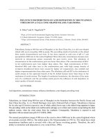
a) B r û l e u r à propane conforme à la f i g u r e 1.
II e s t possible. de placer un adaptateur s u r les brûleurs non
conformes à la figure, afin d'obtenir le diamètre d e 8 mm à la
sortie d e celui-ci.
b)
Bouteille d e propane avec détendeur e t manomètre.
c)
Ecran métallique dont les dimensions sont les suivantes:
hauteur
1 200 t 25 mm;
largeur
300 f 25 mm;
profondeur
450 2 25 mm. La p a r t i e a v a n t est ouverte, le plancher e t le plafond
sont obturés (voir f i g u r e 3).
d) Chronomètre.
e)
Etuve à chauffage électrique. '
COPYRIGHT International Electrotechnical Commission
Licensed by Information Handling Services
>
~~
IEC 3 3 2 P T m 2 87 rn 4844873 0 0 2 7 0 4 7
332-2
@
Y
- 5 -
IEC
TESTS ON ELECTRIC CABLES UNDER FIRE CONDITIONS
P a r t 2: T e s t on a single small vertical insulated
copper w i r e or cable
1.
Scope
T h i s standard ‘specifies a method o f testing a small insulated w i r e
u n d e r f i r e conditions when the method specified in IEC Publicat i o n 332-1 i s not suitable because some small conductors may melt
during t h e application o f t h e flame. T h e range o f application recommended i s f o r solid copper conductors from 0.4 mm to 0.8 mm diameter
and f o r stranded conductors from 0.1 mmS2 t o 0.5 mm2 cross-section.
T h i s standard includes t h e requirement f o r compliance.
Note.-
2.
T h e use o f insulated w i r e which complies w i t h t h i s standard is
not sufficient t o p r e v e n t flame propagation under a l l conditions
of installation. When t h e r i s k o f propagation is high, such as
with long vertical r u n s of bunches o f wires, it cannot b e
assumed that because a sample complies w i t h t h i s s t a n d a r d t h e
bunch will behave in a similar manner.
Performance requirement
T h e t e s t i s intended f o r t y p e approval testing or may be r e f e r r e d t o
in cable standards.
One sample o f insulated w i r e or cable, a f t e r having been tested i n
accordance with Clauses 6, 7 and 8, shall comply w i t h t h e following
requ i rement :
A f t e r all b u r n i n g has ceased, t h e surface of t h e sample shall be
wiped clean and t h e charred portion shall not have reached w i t h i n
50 mm of t h e lower edge o f t h e t o p clamp.
3.
T e s t equipment
a) Propane b u r n e r complying with t h e requirements o f Figure 1.
It is allowable t o fit an adaptor t o b u r n e r s not exactly complying
with t h e f i g u r e in o r d e r t o obtain t h e 8 mm bore shown.
b ) Propane bottle with pressure device and pressure gauge.
c ) Metal
screen
1 200 f 25 mm high;
300 f 25 mm wide
and
450 f 25 mm deep, with open f r o n t and closed t o p and bottom (see
Figure 3 ) .
d) Stop watch,
e)
Electrically heated oven.
COPYRIGHT International Electrotechnical Commission
Licensed by Information Handling Services
I E C 332 PT*2 87
Ll8L(L(BỵL 0 0 2 7 0 5 0 O
- 6 -
4.
=
332-2 @ CE1
EchantiI Ion
Chaque échantillon est pré1ev.é à l'extrémité du câble à essayer e t
d o i t mesurer 600 f 25 mm. Deux échantillons sont nécessaires, respectivement appelés 1 e t 2.
5.
Préconditionnement
Si le conducteur isolé a une peinture ou une laque d e finition, les
échantillons sont maintenus dans une étuve ( v o i r article 3, point e)) à
la température d e 60 f 2 OC pendant 4 h e t sont ensuite remis à
température ambiante avant l'essai.
6.
Conditions d'essai
L'échantillon e s t tendu e t accroché en position verticale a u centre de
l'écran métallique ( v o i r article 3, point c)). Une charge de 5 N/mm2 d e
section d e conducteur est fixée à la p a r t i e inférieure d e l'échantillon,
d e telle manière que la longuewr d e conducteur comprise e n t r e l'attache
inférieure e t l'attache supérieure soit d e 550 f 25 mm. II est essentiel
d'exclure t o u t courant d'air e t il est recommandé d'entreprendre l'essai
dans une enceinte adaptée, exempte de t o u t courant d'air.
7. Source de chaleur
Le b r û l e u r ( v o i r article 3, point a) e t f i g u r e 1) est alimenté en
propane de faỗon ce qu'il produise une flamme lumineuse lorsqu'il se
t r o u v e en position verticale, l'entrée d ' a i r étant fermée. Le débit de
gaz est alors réglé d e telle manière que l a longueur de l a flamme
lumineuse soit d e 125 f 25 mm ( v o i r figure 2). Une pression d e 1 bar,
lue a u niveau du détendeur ( v o i r article' 3, point b ) ) , est recommandée
p o u r obtenir cette exigence.
Le b r û l e u r est ensuite placé comme s u i t (voir f i g u r e 3). L'axe du
b r û l e u r d o i t f a i r e un angle d e 45' avec l'axe d e l'échantillon. La
distance e n t r e le centre d e la sortie du brûleur e t l a surface de
l'échantillon, mesurée le long d e l'axe du brûleur, d o i t ê t r e d e
10 f 1 mm. La distance du point d'intersection de l'axe du b r û l e u r e t
d e l'axe de l'échantillon a u point d'accrochage de l a charge de 5 N/mm2
d o i t ê t r e d e 100 f 10 mm. La distance d u point d'intersection des axes
du b r û l e u r e t d e l'échantillon à l a partie basse du système d'accrochage supérieur ne d o i t pas dépasser 465 mm.
8.
Procédure d'essai
La flamme est appliquée de telle manière qu'elle enveloppe I'échantillon. Elle est appliquée s u r l'échantillon no 1 pendant une durée
maximale d e 20 2 1 s. Si l'échantillon est intact, à savoir que le
conducteur n'a pas fondu, le résultat d e l'essai est déterminé en
fonction des exigences définies à l'article 2. Si, p a r contre, le
conducteur a fondu au b o u t d'un temps T i n f é r i e u r à 20 f 1 sí l'essai
est r e p r i s s u r l'échantillon no 2 avec une durée d'application d e la
flamme d e ( 7 - 2) s. Le résultat d'essai est alors déterminé s u r
l'échantillon no 2.
COPYRIGHT International Electrotechnical Commission
Licensed by Information Handling Services
o
I E C 3 3 2 P T * 2 4’7 U 4 8 4 4 8 ’ 7 1 0 0 2 9 0 5 3 2
332-2
4.
@
IEC
- 7 -
Sample
Each t e s t sample shall b e taken from t h e end o f t h e test cable and
shall measure 600 f 25 mm. Two such samples shall be available,
designated 1 and 2.
5.
Conditioning before t e s t
If t h e insulated w i r e has a paint o r lacquer f i n i s h t h e samples shall
b e maintained in an oven (Clause 3, Item e)) a t a temperature of
60 f 2 O C f o r 4 h and shall b e cooled t o ambient temperature prior t o
t h e test.
6.
T e s t conditions
T h e sample shall b e straightened and clamped in a vertical position
in t h e centre o f t h e metal screen (Clause 3, Item c)). A load o f
5 N/mm2 of conductor area shall b e attached t o t h e lower p a r t o f t h e
sample so t h a t t h e distance between t h e upper and lower attachments
measures 550 f 25 mm. It is essential t o exclude a l l draughts and it i s
recommended that t h e t e s t is undertaken within a suitable small
draught-free enclosure.
7. Source of heat
The b u r n e r (Clause 3, Item a) and Figure 1) i s f e d w i t h propane so
as t o produce a luminous flame when in a vertical position w i t h t h e a i r
inlet closed. T h e gas flow shall b e adjusted so t h a t t h e total length of
the luminous flame is 125 f 25 mm (see Figure 2). A pressure of 1 b a r
as indicated by t h e pressure reducing device (Clause 3, Item b ) ) is
recommended t o meet t h i s requirement.
T h e burner shall be arranged as follows (see Figure 3). T h e centreline of t h e b u r n e r t o b e a t a n angle of 45O t o t h e centre-line of t h e
sample. T h e g a p between t h e b u r n e r orifice and t h e surface o f t h e
sample measured along t h e centre-line of t h e b u r n e r shall be
10 k I mm. T h e distance between t h e point a t which t h e b u r n e r centreline and sample centre-line intersect and t h e point where t h e load o f
5 N/mm2 is applied shall b e 100 f 10 mm. T h e distance between t h e
point a t which t h e b u r n e r and sample centre-lines intersect and t h e
lower edge o f t h e t o p clamp shall not exceed 465 mm.
0.
T e s t procedure
T h e flame shall b e applied so that it envelops t h e sample. T h e flame
shall be applied t o sample No. 1 for a maximum duration of 20 f 1 s .
If t h e sample is intact, ¡.e. no melting o f conductor, t h e test shall be
evaluated in accordance with Clause 2. Should t h e conductor premat u r e l y melt, a t a time T less than 20 f 1 s, t h e t e s t shall be repeated
on sample No. 2 f o r a - d u r a t i o n of ( T - 2) s . T h e assessment shall
then b e based o n l y on sample No. 2.
COPYRIGHT International Electrotechnical Commission
Licensed by Information Handling Services
I E C 332 P T * 2 8 9 m
*
4844891 0029052 4
m
-a-
332-2 0 CE1
ADétail
Detail A
Vue en coupe
Sectional view
Dimensions en millinMres/Dimensions in millimetres
FIGURE 1
COPYRIGHT International Electrotechnical Commission
Licensed by Information Handling Services
749/88
IEC 3 3 2 P T * 2 87 U Li8114891 0 0 2 9 0 5 3 b
- 9 -
332-2 @ IEC
Enceinte à trols parois
Three sided enclosure
-
-m
Flamme enveloppant
l'échantillon
Flame to envelop
sample
dE
in
d
ln
N
+I
8
in
I
5N/mmz
751/88
750/88
Dimensions en milli&tres/Dimensions
FIGURE 2
COPYRIGHT International Electrotechnical Commission
Licensed by Information Handling Services
in millimetres
FIGURE 3
0
I E C 3 3 2 P T * Z 87 m 4 8 4 4 8 9 1 0 0 2 7 0 5 4 8
Publications de la C E I préparées
par le Comité d’Etudes no 20
I E C publications prepared
by Technical Committee No. 20
55: - Câbles isolés au papier imprégné sous gaine métallique pour des
tensions assignées inférieures ou égales à 18/30 kV
(avec âmes conductrices en cuivre ou aluminium et à
l’exclusion des câbles à pression de gaz et à huile
55:
fluide).
Première partie: Essais.
Deuxième partie: Généralités et exigences de construction.
141: - Essais de câbles à huile fluide, à pression de gaz et de leurs
dispositifs accessoires.
141-1 (1976)
Première partie: Câbles au papier à huile fluide et à
gaine métallique et accessoires pour des tensions alternatives inférieures ou égales à 400 kV.
Deuxième partie: Câbles à pression de gaz interne et
141-2 (1963)
accessoires pour des tensions alternatives inférieures
ou égales à 275 kV.
Modification no 1 (1967).
Troisième partie: Câbles à pression de gaz externe (à
141-3 (1963)
compression de gaz) et accessoires pour des tensions
alternatives inférieures ou égales à 275 kV.
Modification no 1 (1967).
Quatrième partie: Câble à huile fluide en tuyau à
141-4 (1980)
isolation de papier imprégné sous forte pression
d’huile et accessoires pour des tensions alternatives
inférieures ou égales à 400 kV.
173 (1964)
Couleurs pour les conducteurs des câbles souples.
183 (1984)
Guide pour le choix des câbles à haute tension.
227: - Conducteurs et câbles isolés au polychlorure de vinyle, de
tension nominale au plus égale à 450/750 V.
227-1 (1979)
Première partie: Prescriptions générales.
Modification no 1 (1985).
227-2 (1979)
Deuxième partie: Méthodes d’essais.
Modification no 1 (1985).
227-3 (1979)
Troisième partie: Conducteurs pour installations
fixes.
227-4 (1979)
Quatrième partie: Câbles sous gaine pour installations
55-1 (1978)
55-2 (1981)
-
Paper-insulated metal-sheathed cables for rated voltages up to
18/30 kV (with copper or aluminium conductors and
excluding gas-pressure and oil-filled cables).
55-1 (1978)
55-2 (1981)
141:
Part 1: Tests.
Part 2: General and construction requirements.
Tests on oil-filled and gas-pressure cables and their accessories.
141-1 (1976)
Part 1 : Oil-filled, paper-insulated, metal-sheathed
cables and accessories for alternating voltages up to
and including 400 kV.
Part 2: Internal gas-pressure cables and accessories
141-2 (1963)
for alternating voltages up to 275 kV.
-
141-3 (1963)
141-4 (1980)
Amendment No. 1 (1967).
Part 3 : External gas-pressure (gas compression) cables
and accessories for alternating voltages up to
275 kV.
Amendment No. 1 (1967).
Part 4: Oil-impregnated paper-insulated high pressure
oil-filled pipe-type cables and accessories for alternating voltages up to and including 400 kV.
Colours of the cores of flexible cables and cords.
173 (1964)
Guide to the selection of high-voltage cables.
183 (1984)
227: - Polyvinyl chloride insulated cables of rated voltages up to and
including 450/750 V.
Part 1 : General requirements.
227-1 (1979)
Amendment No. 1 (1985).
Part 2: Test methods.
227-2 (1979)
Amendment No. 1 (1985).
Part 3: Non-sheathed cables for fixed wiring.
227-3 (1979)
227-4 (1979)
Part 4: Sheathed cables for fixed wiring.
227-5 (1979)
227-6 (1985)
Part 5 : Flexible cables (cords).
Part 6: Lift cables and cables for flexible connections.
Conductors of insulated cables.
First supplement: Guide to the dimensional limits of
circular conductors.
Tests on cable oversheaths which have a special protective function and are applied by extrusion.
fiXeS.
227-5 (1979)
227-6 (1985)
Cinquième partie: Câbles souples.
Sixième partie: Câbles pour ascenseurs et câbles pour
connexions souples.
228 (1978)
Ames des câbles isolés.
228A (1982)
Premier complément: Guide pour les limites dimensionnelles des âmes circulaires.
229 (1982)
Essais sur les gaines extérieures des câbles, qui ont une
fonction spéciale de protection et sont appliquées par
extrusion.
Essais de choc des câbles et de leurs accessoires.
230 (1966)
245: -Conducteurs et câbles isolés au caoutchouc, de tension nominale
au plus égale à 450/750 V.
Première partie: Prescriptions générales.
245-1 (1980)
Deuxième partie: Méthodes d’essais.
245-2 (1980)
Modification no 1 (1985).
Troisième partie: Conducteurs isolés au silicone, résis245-3 (1980)
tant à la chaleur.
Modification no 1 (1985).
245-4 (1980)
Quatrième partie: Câbles souples.
Modification no 1 (1985).
Cinquième partie: Câbles souples pour ascenseurs.
245-5 (1980)
Modification no 1 (1985).
Sixième partie: Câbles souples pour électrodes de sou245-6 (1980)
dage à l’arc.
Modification no 1 (1985).
Calcul du courant admissible dans les câbles en régime
287 (1982)
permanent (facteur de charge lOO?h).
Caractéristiques des câbles électriques résistant au
331 (1970)
feu.
332: - Essais des câbles électriques soumis au feu.
Première partie: Essai effectué sur un câble vertical.
332-1 (1979)
332-2 (1989)
332-3 (1982)
Deuxième partie: Essai sur un petit conducteur ou
câble isolé à âme en cuivre, en position verticale.
Troisième partie: Essais sur câbles en nappes.
Modification na 1 (1984).
(Suire QU verso)
COPYRIGHT International Electrotechnical Commission
Licensed by Information Handling Services
228 (1978)
228A (1982)
229 (1982)
Impulse tests on cables and their accessories.
230 (1966)
245: - Rubber insulated cables of rated voltages up to and including
450/750 V.
Part 1 : General requirements.
245-1 (1980)
Part 2: Test methods.
245-2 (1980)
Amendment No. 1 (1985).
Part 3: Heat resistant silicone insulated cables.
245-3 (1980)
245-4 (1980)
245-5 (1980)
245-6 (1980)
287 (1982)
331 (1970)
Amendment No. 1 (1985).
Part 4: Cords and flexible cables.
Amendment No. 1 (1985).
Part 5: Lift cables.
Amendment No. 1 (1985).
Part 6: Arc welding electrode cables.
Amendment No. 1 (1985).
Calculation of the continuous current rating of cables
(100Y0 load factor).
Fire-resisting characteristics of electric cables.
332: - Tests on electric cables under fire conditions.
Part 1: Test on a single vertical insulated wire or
332-1 (1979)
cable.
Part 2: Test on a single small vertical insulated copper
332-2 (1989)
wire or cable.
Part 3: Tests on bunched wires or cables.
332-3 (1982)
Amendment No. 1 (1984).
(Coiifiiiued overleaf)
I E C 332 P T * 2 8 9
4844891 0029055 T W
Publications de la C E I préparées
par le Comité d’Études no 20 (Suite)
I E C publications prepared
by Technical Committee No. 20 (Continued)
Câbles de transport d’énergie isolés par diélectriques
massifs extrudés pour des tensions assignées de 1 kV à
30 kV.
Modification no 1 (1984).
Méthodes d’essais pour les enveloppes isolantes et les
540 (1982)
gaines de câbles électriques rigides et souples (mélanges élastomères et thermoplastiques).
Comparaison des câbles souples de la C E 1 et des
541 (1976)
câbles souples de l’Amérique du Nord.
Câbles à isolant minéral et leurs terminaisons de ten702-1 (1988)
sion nominale ne dépassant pas 750 V. Première partie: Câbles.
702-2 (1986)
Deuxième partie: Terminaisons.
Calcul des valeurs minimales et maximales des dimen719 (1981)
sions extérieures moyennes des conducteurs et câbles à
âmes circulaires en cuivre et de tension nominale au
plus égale à 450/750 V.
Guide aux limites de température de court-circuit des
724 (1984)
câbles électriques de tension assignée au plus égale à
0,6/ 1,O kV.
754: - Essai des gaz émis lors de la combustion des câbles électriques.
754-1 (1982)
Première partie: Détermination de la quantité de gaz
acide halogéné émis lors de la combustion d’un matériau polymérisé prélevé sur un câble.
800 (1984)
Câbles chauffants de tension nominale 300/500 V
pour le chauffage des locaux et la protection contre la
formation de glace.
811: -Méthodes d’essais communes pour les matériaux d’isolation et
de gainage des câbles électriques.
81 1-1-1 (1985) Première partie: Méthodes d’application générale.
Section un -Mesure des épaisseurs et des dimensions
extérieures - Détermination des propriétés mécaniques.
811-1-2 (1985) Section deux - Méthodes de vieillissement thermique.
811-1-3 (1985) Section trois - Méthode de détermination de la
masse volumique -Essai d‘absorption d‘eau - Essai
de rétraction.
811-1-4 (1985) Section quatre - Essai à basse température.
811-2-1 (1986) Deuxième partie: Méthodes spécifiques pour les mélanges élastomères. Section un - Essai de résistance à
l’ozone - Essai d’allongement à chaud - Essai de
résistance à i’huile.
81 1-3-1 (1985) Troisième partie: Méthodes spécifiques pour les mélanges PVC. Section un - Essais de pression à température élevée - Essais de résistance à la fissuration.
811-3-2 (1985) Section deux - Essais de perte de masse - Essais de
stabilité thermique.
81 1-4-1 (1985) Quatrième partie: Méthodes spécifiques pour les
mélanges polyéthylène et polypropylène. Section un
- Résistance aux craquelures sous contraintes dues à
l’environnement - Essai d’enroulement après vieillissement thermique dans l’air - Mesure de l’indice de
fluidité à chaud - Mesure dans le PE du taux de noir
de carbone &/ou des charges minérales.
Essais des câbles de transoort d‘énergie
840 (1988)
- à isolation
extrudée pour des tensions assignées supérieures à
30kV (U, = 36kV) et jusqu’à 150kV (U,,,=
170 kv).
885: - Méthodes d‘essais électriques pour les câbles électriques.
885-1 (1987)
Première partie: Essais électriques pour les câbles, les
conducteurs et les fils, pour une tension inférieure ou
égale à 450/750 V.
885-2 (1987)
Deuxième partie: Essais de décharges partielles.
885-3 (1988)
Troisième partie: Méthodes d’essais pour mesures de
décharges partielles sur longueurs de câbles de puissance extrudés.
Calcul des courants de court-circuit admissibles au
949 (1988)
plan thermique, tenant compte des effets d’un échauffement non adiabatique.
502 (1983)
502 (1983)
540 (1982)
541 (1976)
702-1 (1988)
COPYRIGHT International Electrotechnical Commission
Licensed by Information Handling Services
Amendment No. I (1984).
Test methods for insulations and sheaths of electric
cables and cords (elastomeric and thermoplastic compounds).
Comparative information on I E C and North American flexible cord types.
Mineral insulated cables and their terminations with a
rated voltage not exceeding 750 V. Part 1 : Cables.
702-2 (1986)
719 (1981)
Part 2: Terminations.
Calculation of the lower and upper limits for the
average outer dimensions of cables with circular copper conductors and of rated voltages up to and including 450/750 V.
Cuide to the short-circuit temperature limits of elec724 (1984)
tric cables with a rated voltage not exceeding
0.6/ 1.O kV.
754: - Test on gases evolved during combustion of electric cables.
754-1 (1982)
800 (1984)
Part 1 : Determination of the amount of halogen acid
gas evolved during the combustion of polymeric
materials taken from cables.
Heating cables with a rated voltage of 300/500 V for
comfort heating and prevention of ice formation.
81 1 : - Common test methods for insulating and sheathing materials of
electric cables.
811-1-1 (1985) Part 1 : Method for general application. Section One
- Measurement of thickness and overall dimensions
- Tests for determining the mechanical properties.
811-1-2 (1985)
Section Two
811-1-3 (1985)
Section Three - Method for determining the density
- Water absorption tests - Shrinkage test.
81 1-1-4 (1985)
811-2-1 (1986)
Section Four - Tests at low temperature.
Part 2: Methods specific to elastomeric compounds.
Section One -Ozone resistance test - Hot set test Mineral oil immersion test.
811-3-1 (1985)
Part 3 : Methods specific to PVC compounds. Section
One - Pressure test at high temperature - Tests for
resistance to cracking.
811-3-2 (1985)
Section Two - Loss of mass test - Thermal stability
test.
Part 4: Methods specific to polyethylene and polypropylene compounds. Section One - Resistance to environmental stress cracking - Wrapping test after
thermal ageing in air - Measurement of the melt flow
index - Carbon black and/or mineral filler content
measurement in PE.
81 1-4-1 (1985)
840 (1988)
- Thermal
ageing methods.
Tests for power cables with extruded insulation for
rated voltages above 30 kV (U, = 36 kV) up to
150kV ((I,= 170kV).
885 : - Electrical test methods for electric cables.
885-1 (1987)
Part 1 : Electrical tests for cables, cords and wires for
voltages up to and including 450/750 V.
885-2 (1987)
885-3 (1988)
Part 2: Partial discharge tests.
Part 3: Test methods for partial discharge measurements on lengths of extruded power cable.
949 (1988)
Calculation of thermally permissible short-circuit currents, taking into account non-adiabatic heating
effects.
PRINTED IN SWITZERLAND
Publication 332-2
Extruded solid dielectric insulated power cables for
rated voltages from 1 kV up to 30 kV.
by Journal d e Genève, Geneva