Simple projects you can make at home
Bạn đang xem bản rút gọn của tài liệu. Xem và tải ngay bản đầy đủ của tài liệu tại đây (23.15 MB, 303 trang )
www.elsolucionario.org
Simple Projects
you can make at home
www.elsolucionario.org
© EFY Enterprises Pvt Ltd
First Published in this Edition, May 2011
All rights reserved. No part of this book may be reproduced in any
form without the written permission of the publishers.
ISBN 978-81-88152-24-7
Published by Ramesh Chopra for EFY Enterprises Pvt Ltd,
D-87/1, Okhla Industrial Area, Phase 1, New Delhi 110020
Typeset at EFY Enterprises Pvt Ltd and
Printed at Nutech Photolithographers, B-38, Okhla Industrial Area,
Phase-I, New Delhi 110020
Y-56, Okhla Phase 2, New Delhi 110020
Simple Projects
you can make at home
EFY Enterprises Pvt Ltd
D-87/1 Okhla Industrial Area, Phase 1
New Delhi 110020
EFY Books & Publications
FOR YOU
EFY is a reputed information house, specialising in electronics and information technology
magazines. It also publishes directories and books on several topics. Its current publications are:
(A) CONSTRUCTION PROJECTS
1. Electronics Projects, Vol. 1: A compilation of selected construction projects and circuit ideas published in Electronics For You magazines between 1979 and 1980.
2. Electronics Projects, Vol. 2 to 19: Yearly compilations (1981 to 1998) of interesting and useful construction projects and circuit ideas published in Electronics For You.
3. Electronics Projects, Vol. 20 to 25 (with CD): Yearly compilations (1999 to 2004).
(B) OTHER BOOKS
1. Learn to Use Microprocessors: By K. Padmanabhan and S. Ananthi (fourth enlarged edition). An EFY publication, extremely useful for the study of 8-bit processors at minimum expense.
2. ABC of Amateur Radio and Citizen Band: Authored by Rajesh Verma, VU2RVM, it deals exhaustively with the
subject—giving a lot of practical information, besides theory.
3. Batteries: By D.Venkatasubbiah. This publication describes the ins and outs of almost all types of batteries used in
electronic appliances.
4. Chip Talk: By Gp Capt (Retd) K. C. Bhasin. The book explains fundamentals of electronics and more than 40
fully tested electronic projects.
5. Modern Audio-Visual Systems Including MP4, HD-DVD and Blu-ray: Explains disk working principles,
troubleshooting and servicing by Gp Capt (Retd) K. C. Bhasin.
6. Microcontroller Based Projects: It is a compilation of 26 construction projects tested at EFY Lab. It covers some commonly available microcontrollers from Atmel Corporation, Microchip Technology Inc. and Freescale Semiconductor Inc.
(C)DIRECTORIES
EFY Annual Guide (with CD): Includes Directory of Indian manufacturing and distributing units, Buyers’
Guide (yellow pages) and Index of Brand Names, plus lots of other useful information.
Educational Directory: Includes courses’ guide and directory of technical institutes in India with state-/
city-wise listing.
(D)MAGAZINES
1. Electronics For You: In regular publication since 1969, EFY is the natural choice for the entire electronics fraternity, be it the businessmen, industry professionals or hobbyists. From microcontrollers to DVD players, from PCB
designing software to UPS systems, all are covered every month in EFY.
2. Linux For You (with DVD): Asia’s first magazine on Linux. Completely dedicated to the Open Source community. Regular columns by Open Source evangelists. With columns focused for newbies, power users and developers, LFY is religeously read by IT implementers and CXOs every month.
3. Facts For You: A monthly magazine on business and economic affairs. It aims to update the top decision makers
on key industry trends through its regular assortment of Market Surveys and other important information.
4. BenefIT: A technology magazine for businessmen explaining how they can benefit from IT.
5. Electronics Bazaar: A monthly B2B magazine for sourcing electronics components, products and machineries.
Ideal for buying decision makers and influencers from electronics and non-electronics industry.
For retail orders:
Kits‘n’Spares
D-88/5, Okhla Industrial Area,
Phase 1, New Delhi 110020
Phone: (011) 26371661, 26371662
E-mail:
Website: www.kitsnspares.com
For magazine subscriptions:
EFY Enterprises Pvt Ltd
D-87/1 Okhla Industrial Area, Phase 1
New Delhi 110020
Phone: (011) 26810601-03
Fax: (011) 26817563
E-mail:
For bulk orders:
IBH Books & Magazine
Distributors Pvt Ltd
Arch No. 29 (West Approach) below
Mahalaxmi Bridge, Mumbai 400034
Phone: (022) 40497427, 40497474
E-mail:
www.elsolucionario.org
PREFACE
T
his book on home projects may be of interest to you if you are studying electronics, or if you are a hobbyist
or an experimenter and wish to learn electronics in a practical way. The projects in this book explain the
working and construction of various circuits, which can be easily assembled at home with few basic tools.
These projects are basically for domestic as well as hobby applications. However, some of these projects may also
be found useful in industrial applications.
This book, a collection of hardware-based projects which appeared in Electronics For You from year 1979 to
2004, is brought out for the benefit of our new readers. It is a compilation of 60 construction projects tested at
EFY Lab.
The book contains projects with comprehensive functional description, construction details such as PCB and
component layouts and parts list. Some projects also cover testing steps, equivalent part names of some hard to
find components and lead/pin identification details of semiconductor devices and integrated circuits (ICs).
The book is divided into five sections in accordance with the application of the circuits: Alarm, Controller and
Indicator, Display and Lighting, Timer and Clock and Game. The Alarm section contains seven projects covering various alarm circuits including Electronic Bell System, Multichannel Fire Alarm System, etc. Some of these
circuits can be used at homes as well as industrial buildings. The Controller and Indicator section contains twentyfour projects covering circuits like Digital Water-Level Indicator-cum-Pump Controller, DTMF Remote Control
System, Long-Range Remote Control, etc. The Display and Lighting section contains eight projects including
Economical UPS for Cordless Phones, Multi-Feature Emergency Light, Multilingual Numerical Display, etc. The
Timer and Clock section contains twelve projects including Digital Clock with Seconds and Alarm Time Display,
Programmable Digital Timer-cum-Clock, LED Analogue Clock, etc. The Game section is specially included here
for the students and beginners with the aim to encourage them to learn electronics while they play. It contains nine
projects including, A Mighty Gadget with Multiple Applications, Digital Number Shooting Game, Electronic
Housie Player, Video Car-Racing Game, The Mind Reader, etc.
Although the book is intended for hobbyist and beginners, a good knowledge of electricity and digital electronics will be helpful. The book can be used by engineering students, teachers, practicing engineers, and hobbyists.
Some printed circuit boards and major components of the projects described in this book are available with our
associates Kits'n'Spares at reasonable prices.
By going through the descriptions of the projects in this book, readers may be able to construct each project
in “Do-it-Yourself ” way. It is hoped that this book will benefit those who are searching for electronic hardwarebased projects.
TABLE OF CONTENTS
Alarm Circuits
1
2
3
4
5
6
7
Electronic Bell System............................................................................................................................. 3
All-In-One Alarm................................................................................................................................... 8
Multichannel Fire Alarm System.......................................................................................................... 13
Fire Sensing System............................................................................................................................... 18
12-Tune Musical Door Bell................................................................................................................... 21
Burglar Alarm to Protect Your Home.................................................................................................... 23
Auto Shut-Off Door Lock Alarm......................................................................................................... 27
Controller and Indicator Circuits
8
9
10
11
12
13
14
15
16
17
18
19
20
21
22
23
24
25
26
27
28
29
30
31
Digital Water-Level Indicator-Cum-Pump Controller......................................................................... 33
Ultrasonic Lamp Brightness Controller................................................................................................. 40
Sound Operated On/Off Switch............................................................................................................ 44
Remote Controlled Sophisticated Electronic Code Lock...................................................................... 48
DTMF 8-Channel Switching Via Powerline........................................................................................ 57
DTMF Remote Control System........................................................................................................... 62
Automatic Room Light Controller........................................................................................................ 73
A Unique Liquid Level Indicator ......................................................................................................... 78
Intelligent Water Level Controller......................................................................................................... 81
Automatic Submersible Pump Controller.............................................................................................. 86
Tripping Sequence Recorder-Cum-Indicator........................................................................................ 90
Electrolysis-Proof Complete Water-Level Solution.............................................................................. 94
Long-Range Remote Control.............................................................................................................. 100
Remote Controlled Switch Board........................................................................................................ 104
Multiple Control Remote Switch........................................................................................................ 112
Infrared Remote Control..................................................................................................................... 117
Auto-Changing In/out Indicator with Door-Bell............................................................................... 121
Safety Indicators and Aids................................................................................................................... 124
Watchdog For Your Mains................................................................................................................... 129
Auto Protection For Refrigerator......................................................................................................... 132
Clap-Operated Remote Control for Fans............................................................................................ 135
Refrigerator Temperature Controller................................................................................................... 138
A Volunteer in the Kitchen.................................................................................................................. 141
A Day Indicator With Alphabetical Display....................................................................................... 145
Display and Lighting Circuits
32
33
34
35
36
37
38
39
Economical UPS For Cordless Phones................................................................................................ 153
Multi-Feature Emergency Light.......................................................................................................... 158
Novel Mains Running Lights.............................................................................................................. 162
Spectacular Spectra.............................................................................................................................. 166
Dynamic Psychedelic Lights................................................................................................................ 171
Multilingual Numerical Display.......................................................................................................... 175
Electronic Advertisement Display ...................................................................................................... 181
Make Yourself This Beeper-Cum-Flasher............................................................................................ 186
Timer and Clock Circuits
40
41
42
43
44
45
46
47
48
49
50
51
Digital Clock Using Discrete ICs........................................................................................................ 191
Digital Clock With Seconds And Alarm Time Display...................................................................... 197
Simple Digital Clock With Hourly Music.......................................................................................... 203
Digital Dial Clock............................................................................................................................... 207
Programmable Digital Timer-Cum-Clock.......................................................................................... 212
Revolving Seconds Display.................................................................................................................. 217
Kettle Timer........................................................................................................................................ 224
Melodious Digital Timepiece.............................................................................................................. 227
Improve Your Digital Clock................................................................................................................. 234
Add Hourly Chime To Your Digital Clock......................................................................................... 237
LED 'Analogue' Clock........................................................................................................................ 241
Make Yourself This Crystal-Controlled Electronic Digital Clock....................................................... 246
Game Projects
52
53
54
55
56
57
58
59
60
MGMA—A Mighty Gadget With Multiple Applications................................................................. 253
Digital Number Shooting Game......................................................................................................... 259
Party Game: How Old Are You?......................................................................................................... 263
Electronics Housie Player.................................................................................................................... 267
Digital Scoreboard............................................................................................................................... 272
Yoka Fun Box....................................................................................................................................... 277
Video Car-Racing Game..................................................................................................................... 281
Make Yourself The Mind Reader — An Interesting Game................................................................. 285
Make Yourself This Digital Birth Date Teller As a Party Game.......................................................... 289
www.elsolucionario.org
Alarm Circuits
www.elsolucionario.org
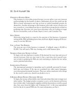
Electronic Bell System
D.K. Kaushik
I
n this innovative project, a simple electronic bell system using commonly available ICs is presented for use in
educational institutes. This simple and easy-to-fabricate project has the following features:
• It sounds the bell automatically after every period of 40 minutes.
• It displays in digital form the current time and period number of the class going on.
• The system automatically switches off after the last period (11th period). The digital clock showing the current
time, however, continues working as usual.
The principle
Fig. 1 shows the block diagram of the system, which has three parts. Part I has the usual digital clock comprising
quartz crystal oscillator cum frequency divider IC MM5369, clock chip
Parts List
MM5387, and 7-segment common-cathode displays.
Semiconductors:
The 1Hz pulse (i.e. one pulse per sec.) is taken from the digital
IC1
-7805 +5V regulator
clock and used in part II of the circuit. The accuracy of the system
IC2
-7474 dual ‘D’ flip-flop
depends on this 1Hz pulse, obtained from the standard digital clock
IC3
-MM5369 oscillator/driver
IC4
-MM5387/LM8361 clock
chip or equivalent
IC5, IC6
-CD4026 decimal up-counter
with 7-segment driver
IC7-IC10
-CD4017 decade counter
T1, T2
-BC107/BC547 npn transistor
T3, T4
-2N2222 npn switching
transistor
D1-D8
-1N4001 rectifier diode
LED1, LED2 -Red LED
Resistors (all ¼-watt, ±5% carbon, unless
stated otherwise):
-2.2-kilo-ohm
R1, R2
R3, R44, R50 -1.5-kilo-ohm
R4
-4.7-kilo-ohm
R5, R6, R45
R46, R48
-10-kilo-ohm
-330-ohms
R7-R43
R47
-56-kilo-ohm
R49
-20-mega-ohm
Capacitors:
C1, C4
-100µF, 25V electrolytic
C2
-30pF ceramic disk
C3
-30pF trimmer
Miscellaneous:
S1-S4
-Tactile switch (SPST)
S5
-Tactile switch (DPDT)
XTAL
-3.57945MHz crystal
RL1-RL2
-12V, 200-ohm relay (SPST)
DIS.1-DIS.6 -LT543 common-cathode
7-segment display
-Power amplifier with loudspeaker
Simple Projects
Fig. 1: Block diagram of the electronic bell system
3
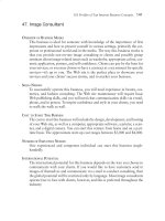
Fig. 2: Schematic diagram of electronic bell system for institutes
4
circuit. In part II of the
system, the 1Hz pulse is
used to obtain one pulse
after every 40 minutes, by
employing a four-stage
counter circuit.
The pulses obtained
at 40-minute intervals drive transistor T4
(see Fig. 2) into saturation for a few seconds
(the exact duration being
decided by the delay circuit
comprising 56-kilo-ohm resistor R47, 100µF capacitor
C4, and diode D7). When
the transistor goes into
saturation, relay RL2 is energised and the bell sounds
for a few seconds.
Any electronic horn/
siren using an audio power
amplifier of desired wattage
may be used for the bell. In
the prototype, the author
used an audio tape recorded
with the usual sound of brass
bell, with tape recorder/player of 150 watts rating, driving
four 20-watt speaker units. It
is considered adequate for the
campus of any educational
institute. The readers may,
however, use any other sound
system according to their
requirements.
Part III consists of the
period counter and display.
It displays the current period
in progress. The number of
pulses received at 40-minute
intervals are counted by this
counter circuit and the display unit displays the period
number.
One additional relay
circuit is used so that the
power supply given to parts
II and III of the system is
automatically interrupted
at the end of the eleventh
Simple Projects
period. Next day the
system has to be reset,
and the cycle repeats.
The circuit
Fig. 2 shows the detailed
circuit diagram. The Fig. 3: Pin configuration of MM5369
clock circuit of part I
of the system is designed using 3.58MHz quartz crystal,
MM5369 crystal oscillator and divider (IC3), MM5387
clock chip (IC4), four common-cathode 7-segment
displays, and a few passive components. For more details
of the digital clock, the readers may consult ‘Car Clock
Module’ project in September 1986 issue or Electronics
Projects (Vol. 7) published by EFY. Push-to-on switches
S1 and S2 (slow and fast time set) may be used to set the
time of the digital clock.
(Note. For ready reference, pin configurations of ICs
MM5369 and MM5387/LM8361 are reproduced here in
Figs 3 and 4, respectively.)
The standard 1Hz pulse is taken from pin 39 of IC4
and connected to clock input pin 14 of decade counter
IC7 (CD4017). The carry pin 12 of IC7 outputs a pulse
every 10 seconds, which is connected to clock pin 14
of the next CD4017 decade counter (IC8). The reset
terminal (pin 15) of IC8 is connected to pin 5 (output Fig. 4: Pin configuration of IC MM5387/LM8361
Fig. 5: PCB layout
Simple Projects
5
www.elsolucionario.org
No. 6) of the same IC. This IC thus divides
the signal by a factor of 6 and its pin 12
(carry pin) gives an output of one pulse
every minute. This pulse is applied to IC9
(CD4017), where it is further divided by a
factor of 10 to produce an output pulse at
every 10-minute interval. Finally, a pulse at
every 40-minute interval is obtained from
IC10 (CD4017), which is configured as
divide-by-four counter, since its reset pin
15 is shorted to Q4 output pin 10 of IC10.
The output pulse at pin 3 of IC10 remains high for ten minutes and low for 30
minutes. This output pulse (every 40 minutes) is connected to the base of transistor
T4 through a combination of capacitor C4
and resistance R47, to energise the relay and
sound the bell. The capacitor-resistor combination of C4-R47 acts as a differentiator
circuit, while diode D7 clips off the negative
going portion of the pulse. The delay time
may be adjusted by choosing proper C4-R47
combination values.
After the preset time delay of a few
seconds, the transistor goes into cut-off and
the relay gets de-energised, to switch off
the bell. However, the clock circuit of part
I around IC4 and divider circuit formed
by IC7 through IC10 continue to work as
usual and hence the accuracy of the periods
is not affected by the ‘on’ and ‘off ’ times of
transistor T4.
To count and display the current period,
a two-digit counter is designed using two
CMOS decade counter cum 7-segment
decoder/driver CD4026 ICs (IC5 and
IC6) and two 7-segment common-cathode
displays (LT543). The pulse obtained every
40 minutes from pin 3 of IC10 is also connected to the input of this two-digit counter.
Fig. 6: Component layout
This counter counts these pulses and displays
them via the LT543 (showing the current
period number in progress). The two-digit counter counts and displays the period number up to 11.
The segment ‘d’ output for most significant digit (MSD) and segment ‘c’ output for least significant digit (LSD)
from IC5 and IC6 are connected to the bases of transistors T1 and T2 respectively, via 2.2-kilo-ohm resistors
R1 and R2. The collectors of the two transistors are connected together, working as a NOR gate. When ‘d’ and
‘c’ segment driving outputs from IC5 and IC6 respectively, go low simultaneously (just at the beginning of 12th
period), the output (common collector voltage of transistors T1 and T2) goes high. This output is also connected
to clock pin 3 of IC2 (IC 7474), which is a dual ‘D’ flip-flop.
Only one of the two flip-flops is used here in toggle mode by connecting its Q pin 6 to data (D) pin 2. The
flip-flop toggles after every clock pulse. The ‘Q’ output of this flip-flop drives relay RL1 through transistor T3,
6
Simple Projects
and thus switches off the supply to parts II and III of the system, just at the beginning of 12th period (i.e. at the
end of 11th period). Resumption of the supply may take place the next day after momentarily pressing switch S3.
For power supply, a 12V car battery with charging facility is recommended.
An actual-size, single-sided PCB for the circuit (Fig. 2) is shown in Fig. 5 and the component layout for the
PCB in Fig. 6.
Operation
After completing the circuit, test the circuit according to circuit description, as discussed above. For operation
of the circuit, switch S3 is momentarily pressed for resumption of the supply to parts II and III of the circuit, as
relay RL1 is energised. Period-displaying 7-segment displays DIS.5 and DIS.6 will display any random number,
which is reset to 00 by momentary depression of switch S4.
Further, switch S5 (DPDT) is pressed and then released exactly at the time when the first period is to start.
This resets IC7 through IC10. The output Q0 at pin 3 of IC10 will go high, to energise the relay and thus switch
on the bell for a few seconds and advance the period display from 00 to 01 (indicating that the first period has
started).
Hereafter, the circuit works automatically, sounding the bell for a few seconds after every 40 minutes. In the
evening, after the eleventh period is over and the institute is to be closed, the power supply to parts II and III of
the circuit gets automatically switched off. Though the ringing of bell and display of periods discontinue, the digital
clock continues to work as usual. Next morning, the above operation needs to be repeated.
Simple Projects
7
All-in-one Alarm
A. Jeyabal
I
n our everyday life, we use different types of audio indicators such
as a doorbell to inform that someone is waiting at the door step, a
telephone ring to inform that some one is calling, the alarm in the
digital clock to wake up at a particular time, a beeper in the keyboard to
confirm the key is pressed or not, and a buzzer in the washing machine
to announce that washing is completed. But all these audio indicators
are used for a particular function and cannot be easily put to use for
other jobs.
An all-in-one multipurpose alarm circuit is described here. It finds
multiple applications from a simple game, water level monitor, to voltage alarm, to continuity tester, to security alarm. It gives continuous and
interrupted alarms which can be activated by both high and low level
pulse in the trigger mode and a high level voltage in the normal mode.
Circuit description
Parts List
Semiconductors:
IC1
-4093 quad 2-input NAND
gate with schmitt trigger
input
T1
-BC 557 general-purpose pnp
transistor
Resistors (all ¼-watt, ±5% carbon, unless stated
otherwise):
R1-R3
-10-kilo-ohm
R4
-100-kilo-ohm
-100-kilo-ohm pot.
VR1, VR3
-1M pot.
VR2
Capacitors:
C1
-0.01µF ceramic disk
C2
-2.2µF, 12V electrolytic
C3
-1000µF, 12V electrolytic
Miscellaneous:
-SPST switch
S1, S4
S2
-SPDT switch
-Push-to-on switch
S3
LS
-8-ohm 6.25cm speaker
-Earphone socket
Sockets 1-3
-1.5V cell (4 nos)
Battery
-6-cell battery box
Fig. 1 shows the block diagram of the circuit. Block 1 produces highfrequency oscillations in the audio range which are amplified by block
2 to drive the speaker.
The control terminal of the oscillator is connected to the input
through switch S2. A distinct tone is produced whenever a positive
voltage above the threshold voltage is applied to the control terminal.
The low frequency oscillations are produced by block 3, and its
output is connected to the control terminal of block 1 through a diode and S1. Whenever the output of block 3
goes low, it disables the high-frequency oscillator
and an interrupted tone is heard in the speaker.
Switch S2 in the other position connects the
output of flip-flop (block 4) to the control terminals of block 1 and 3. Once triggered by a negative
going pulse, the output of flip-flop goes high to
sound the alarm and remains in that state until the
reset switch is pressed.
Fig. 2 shows the schematic diagram of the
multipurpose alarm. IC 4093 is employed in this
circuit. It contains quad 2-input NAND gates
with schmitt trigger inputs. If any other IC is used,
more than one IC will have to be used.
Continuous alarm
Fig. 1: Block diagram for the multipurpose alarm
8
Gate G1 produces high frequency oscillations
(HFO) around 1000 Hz which is more sensitive
to the human ear. Presume capacitor C1 is in the
Simple Projects
www.elsolucionario.org
discharged condition
and pin 2 (control pin
in the circuit) in the
high level. Now, output
of G1 (pin 3) is high
and charges C1 through
VR1. When the voltage
across C1 goes above
the upper level of the
hysterisis, the output
changes to low state and
the capacitor starts to
discharge. When voltage of C1 falls below
the low level, the output becomes high and
charges C1 again. This
cycle repeates as long as
pin 2 is above the high
level. This frequency can
be varied by VR1.
VR1 can be replaced
with a fixed resistor of
any value between 56k
and 150k to produce a
desired fixed frequency
tone.
Interrupted
alarm
The gate G2 functions
as an astable multivibrator like G1 and produces low frequency ocsillations (LFO) in the range
Table I
between 0.3Hz and 3Hz. It works in the same way as G1. When S1
Truth Table for SRFF (4093)
is closed, during the period output of G2 (pin 4) is low, it pulls down
Pin 8 Pin 13 Output
Output
control terminal (pin 2) of G1 and disables G1. And we hear an interSet
Reset
Pin 10
Pin 11
rupted tone.
0
01 1
Diode D1 blocks positive voltage from reaching pin 2 (G1) since
10 0
1
pin 4 (G2) is high during standby state. Resistor R2 is included to pro1
No change No change tect G2 by reducing positive supply reaching pin 4 and also for proper
1
00 1
1
functioning of LFO.
For alarms like rain alarm, VR2 may be set for low frequency and
for burglar alarm it should be set for high frequency for immediate
attention. A fixed resistor of 220k or 330k may be used in place of VR2.
Fig. 2: Circuit diagram for the multipurpose alarm
Triggered alarm
Gates G3 and G4 are wired as a set-reset flip-flop (SRFF). The truth table is shown in Table I. The input pins 8
and 13 of SRFF are kept at high level. When pin 8 is momentarily held low, output of G3 (pin 10) goes high. This
state is maintained until pin 13 is momentarily held low by reset switch S3. Now, output of G3 (pin 10) goes low
Simple Projects
9
and output of G4 (pin 1) goes high.
R3 protects from short circuit when socket 3 is
used.
Construction
Fig. 3: Actual-size PCB layout for the multipurpose alarm
This circuit can be assembled on the PCBs shown in
Figs 3 and 4.
Easily available six-cell battery box may be used
as a cabinet. Only four cells are needed for the circuit.
Fix the speaker and all other components in the empty
space. Drill a nail hole at the back of the cabinet to
hang it on the wall.
Applications table buzzer/doorbell
Connect wires and a push-to-on switch S5 to an earphone socket pin as shown in Fig. 12. Close S4 and
keep S1, S2 in the normal position and turn VR3 to
the hot end. A tone will be heard in the speaker. Adjust
VR1 to get a pleasing tone. Plug in the earphone pin
into sockets 1. Now, the gadget is ready for use as a
table buzzer.
Fix the gadget inside the house and switch S5 at the
doorstep, and connect them using a lengthy wire. Now
the gadget serves as a door bell.
Game of steady hand
Fig. 4: Component layout for the PCB shown in Fig. 3
Take an electrically conducting wire of 3 mm in diameter and 60 or 70cms long. Take a 10cm rod and bend
one end to a ring.
The inner diameter of the ring should be just bigger than the thickness of the wire mentioned earlier. Insert
the wire into the ring and fix it on a board, as depicted in Fig. 13(a). Wind a piece of non-conducting adhesive
tape on both ends. This serves as a halting place.
The aim of the game is to move the ring along the wire from one end to the other end without touching the
wire. Plug in the pin into socket 1. The alarm device will monitor the game. Whenever the ring touches the wire,
positive supply goes to pin 2 and a beep sound will be heard.
The wire may be bent, as shown in Fig. 13(b) to make the game tough and more fun.
Morse code trainer
Buy a Morse code training unit, or make it yourself with a piece of metal strip, connecting it to the alarm as shown
in Fig. 5. A beep sound will be heard for the duration of the key pressed. Enjoy sending Morse code.
Continuity tester
Set switches S1 and S2 for continuous alarm mode. Turn VR3 to the hot end and connect pin to socket 1. Touch
the terminals of the gadget or resistor or anything of which continuity is to be tested, with the probes. A tone will
confirm the continuity.
Any resistor of value less than 56k can be tested with this alarm unit.
10
Simple Projects
Diode-transistor tester
Fig. 5: Arrangement for Morse code trainer
For testing diodes, test the continuity as mentioned earlier and
once again test it interchanging the probes. If the alarm sounds
on both tests, it means diode is shorted, and no sound implies
diode is open, and a sound for any one of the tests confirms diode
is good. In the same way, test a transistor. Touch the base with one
probe and with the other probe, the collector and then emitter.
Interchange the probes and test once again.
Capacitor tester
Fig. 6: Circuit for continuity checker
Fig. 7: Arrangement for water level monitor
Fig. 8: Rain alarm arrangement
Any capacitor from 1µF and above can be checked. Touch positive
lead with the positive probe and negative lead with the negative
probe. A burst of sound falling in frequency (like a sound of gun
shot) will confirm the capacitor is good. A continuous tone for a
shorted capacitor and no tone for open capacitor will be heard.
To check capacitor of value below 1µF, a shorted one can be
identified using socket 1. If no sound is heard in the above test, it
means the capacitor is either open or good. Set switch S2 in the
trigger mode, connect the probe to socket 3 and touch the leads. If
alarm sounds, the capacitor is good. Discharge the capacitor. Press
the reset button. Test once again to confirm.
Warning: This unit is using 6V power supply. So confirm that
the component under test can withstand this voltage before testing.
Water level monitor
Fig. 9: Intruder alarm
To fill the bath tub, it will take some time. If we forget to close
the cock in time, much of the water will be wasted unnecessarily.
Connect two metal strips or any electrically conducting spoons
(sensors) to the leads of the pin and plug in to socket 1. Set switch
S1 in the interrupted alarm mode and S2 in the normal mode.
Adjust VR2 for low frequency. Hang the sensor probes inside the
tub such that when the desired water level is reached, it touches
the probes (Fig. 7). An interrupted tone will be heard when the
water touches the probes.
Rain alarm
Fig. 10: Burglar alarm arrangement
Etch a pattern in the PCB as shown in Fig. 8 or use a generalpurpose PCB connecting the appropriate tracks. Put it in a standing position in open place where rain drops can fall on it.
The alarm beeps when the rain drops fall on it. Do not forget
to keep S1 in interrupted and S2 in normal position.
Intruder alarm
When we like to protect an area from an intruder, this alarm unit is ready to serve. Keep switch S1 in the interrupted position and S2 in the triggered position.
Simple Projects
11
www.elsolucionario.org
Fig. 11: Circuit for smoke and light interruption
alarm
Run a thin wire around the area to be protected and connect it to
socket 1 as shown in Fig. 9. Turn VR3 to the hot end VR2 to sound
2 or 3 beeps per sec. If the alarm sounds, press reset switch S3. The
alarm stops. Now the alarm is in standby mode. When the wire is
broken by the intruder, without his knowledge the positive supply
is removed and pin 8 of G3 is held low by VR3. This triggers SR
flip-flop and its output (pin 10) goes high.
Burglar alarm
Fig. 12: Arrangement for door-bell/table buzzer
Fig. 13(a): Arrangement for the game of steady
hand
Fix normally open (N/O) switch in the doors and thin wire in series
if necessary. When the door is closed, the switch is closed. Connect
it to socket 1 as shown in Fig. 10. When any one of the doors is
opened, the switch opens or the wire is broken, and positive supply
is removed and pin 8 of G3 is grounded. This negative pulse triggers
the set reset flip-flop and pin 10 goes high to sound the alarm.
Fox normally open switches in parallel under doormat or in
places where the burglar is likely to come in contact with these.
When any one of the switches is pressed, it grounds pin 8 of G3
and its output goes high to sound the alarm. In this alarm keep S1
interrupted and S2 in the triggered position.
Smoke alarm
Keep S1 interrupted and S2 in triggered mode. Now fix an LDR
(light dependent resistor) inside a plastic tube and make connections
to the earphone pin. Place a bulb (6V or higher voltage) in front of
the LDR. Put this set up in a place where smoke will collect.
When light falls on the LDR, its resistance becomes low and
Fig. 13(b): Advanced game of steady hand
pin 8 of G3 is high. When the light is obstructed by smoke, LDR’s
resistance goes high and the voltage available to pin 8 is less than the
lower level voltage, and output (pin 10) goes high to activate the alarm.
In the normal no-smoke condition, adjust VR3 from hot end to ground. Stop adjusting it when the alarm
sounds, and adjust it to the hot end a little. Press the reset switch. If alarm still sounds, adjust VR3 a little and
press reset switch. Now it is ready for use.
In some cases, the alarm will sound when the wiper is at the hot end. It means that the LDR is getting less
light.
Try a high voltage bulb or keep the LDR near the tip of the tube. If there is no change in the situation, it
means the LDR is a high valued one. Include a 56k or 68k resistor in parallel with LDR or try a less resistance
LDR.
The same set up shown in Fig. 11 can be used as a light interrupted alarm to monitor unauthorised entries
of persons.
Socket 1 is for sensors using internal power source and socket 2 is for sensors using external power sources.
The applications mentioned in this article for socket 1 are also applicable to socket 2 when external power source
is used. The external power sources’ voltage should not exceed 6V.
A small speaker may be used to make this unit portable.
While using this alarm for security purposes, a power amplifier and loudspeaker may be connected.
12
Simple Projects
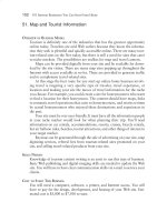
MULTICHANNEL FIRE ALARM
SYSTEM
AMRIT BIR TIWANA
A
lighted cigarette, a burning splinter, an overheated electrical appliance or just about any of these can trigger a
fire; and add to this the presence of foam sofa sets and nylon settings and the poisonous gases that their burning emanates—it hardly needs a few minutes to render persons helpless, even before they realise what’s happening. The multichannel central fire alarm system (FAS) described here could be the best thing to bet your safety on!
A simple, efficient and fail-safe FAS can be built at a very low cost. The project presented has been designed
after careful analysis of the devices commonly available in the market.
Fig. 1: Circuit diagram of the multichannel fire alarm system.
Simple projectS
13
Fig. 2: Actual-size PCB layout for the cirucit shown in Fig. 1.
Semiconductors:
IC1
IC2
IC3
IC4
Parts List
-CD40106, hex schmitt inverter
-CD4049, hex inverter
-CD4068, 8 input NAND
-CD4093, 2 input schmitt quad
NAND
T1
- BD139 npn transistor
D1
- 1N4148 silicon diode
D2-D4
- 1N4001 rectifier diode
Resistors (all ¼-watt, ±5% carbon, unless stated otherwise):
R1
-330-ohms
R2-R7
-2.2-kilohm
R8
-4.7-kilohm
R9-R14
-390-ohms
R15-R17
-680-ohms
VR1-VR6
- 47-kilohm presets
14
Capacitor:
C1-C6
C7
C8
C9
Miscellaneous:
LED1-LED7
X1
-
-
-
-
4.7µF, 12V electrolytic
10nF ceramic disc
470µF, 12V electrolytic
1000µF, 16V electrolytic
-Red LEDs
- 9V, Ni-Cd battery
- Six infrared LEDs
- Six photo-transistors
- Six piezo speakers
- 35mm piezo buzzer
- 230V AC primary to
9V-0-9V, 750 mA secondary transformer
Simple Projects