Tài liệu Enumeration of Kinematic Structures According to Function P8 pdf
Bạn đang xem bản rút gọn của tài liệu. Xem và tải ngay bản đầy đủ của tài liệu tại đây (2.56 MB, 41 trang )
Chapter 8
Automotive Mechanisms
8.1 Introduction
In this chapter, we illustrate the usefulness of the systematic design methodol-
ogy by enumerating a few automotive related mechanisms, including variable-stroke
engine mechanisms, constant-velocity shaft couplings, and automatic transmission
mechanisms.
For each case, we first identify the functional requirements. Then, we translate
some of the requirements into structural characteristics for the purpose of enumeration
of the kinematic structures. Lastly, we apply the remaining functional requirements
along with other requirements, if any, for qualitative evaluation of the kinematic
structures. This results in a class of feasible mechanisms or design alternatives.
Since we are primarily concerned with the enumeration and qualitative evaluation
of various design alternatives, other phases of design such as dimensional synthesis,
design optimization, and design detailing will not be considered.
8.2 Variable-Stroke Engine Mechanisms
Most automobiles employ internal combustionengines as the source of power. Such
a vehicle is typically equipped with an engine that is large enough to meet desired
performance criteria such as maximum acceleration and hill climbing capability. On
the other hand, only a fraction of the engine power is needed for highway cruising.
To meet various load requirements, it is necessary to incorporate some kind of engine
load control mechanism. Most internal combustion engines employ the crank-and-
slider mechanism with a constant stroke length as the engine mechanism. Load
control is achieved by throttling the inlet. Throttling, however, introduces pumping
losses. It becomes clear that engine efficiency can be improved if the throttling can
be eliminated or reduced.
One approach is to employ a mechanism to vary the valve lift, and the valve
opening and closing points, with respect to the engine top-dead-center, as a function
© 2001 by CRC Press LLC
of vehicle load requirements. Another approach is to vary the piston stroke length
and, therefore, the displacement of the engine. More specifically, under light-load
operations, the engine runs at short stroke such that the air-fuel mixture induced in
the cylinder is only sufficient to meet the load requirement. For high-load operations,
the engine runs at long stroke to increase the output power. According to a computer
simulation, an automobile equipped with a variable-stroke engine can potentially
improve its fuel economy by 20% with a concurrent reduction in NO
x
emission [14].
The improvement in fuel economy comes primarily from a reduction of pumping loss
due to the elimination of inlet throttling. Another reason is due to reduction in engine
friction under short stroke operations [17, 18].
In this section, we study the enumeration of a class of variable-stroke engine mech-
anisms.
8.2.1 Functional Requirements
For a variable-stroke engine mechanism to function properly, the mechanism should
be able to maintain a nearly constant compression ratio as the stroke length changes.
It is also desirable to maintain a constant phase angle relation between the top-dead-
center position of the piston and the crankshaft angle. In addition, the time required
to change the stroke length from short to long should be within a few tenths of a
second to meet the acceleration performance requirement. Finally, the mechanism
should be relatively simple and economic to produce. In this regard, the design of a
variable-stroke engine presents a very challenging problem to automotive engineers.
We summarize the functional requirements of a variable-stroke engine mechanism as
follows:
F1. The mechanism should have the capability to change the stroke length as a
function of engine load requirements.
F2. The compression ratio should remain approximately constant for all stroke
lengths.
F3. The top-dead-center position of the piston with respect to the crankshaft angle
should remain approximately constant for all stroke lengths.
F4. The time required to change the stroke from short to long should be within a
few tenths of a second.
F5. The mechanism can be manufactured economically.
8.2.2 Structural Characteristics
There are three types of engine configurations: axial, in-line, and rotary configu-
rations. In an axial configuration, such as the swash-plate and wobble-plate engine
mechanisms, the cylinders are arranged in a circumference with their axes parallel
to the crankshaft. In an in-line configuration, such as the crank-and-slider engine
© 2001 by CRC Press LLC
mechanism, the cylinders are arranged longitudinally with their axes perpendicular
to the axis of the crankshaft to form an in-line or V configuration. A rotary configu-
ration, such as the Wankel engine, consists of two rotating parts: a triangular shaped
rotor and an eccentric output shaft. The rotor revolves directly on the eccentric shaft.
It uses an internal gear that meshes a fixed gear on the engine block to maintain a
correct phase relationship between the rotor and eccentric shaft rotations. The axial
type involves spatial motion and the rotary type requires higher kinematic pairs. In
what follows, we concentrate on the in-line configuration.
Theoretically, a variable-stroke engine mechanism should possess two degrees of
freedom: one for converting reciprocating motion of the piston into rotary motion of
the crankshaft and the other for adjusting the stroke length. To simplify the problem,
we temporarily exclude the degree of freedom associated with the control of stroke
length. Since it is undesirable to incorporate a stroke length controller on a floating
link, the change of stroke length will be accomplished by adjusting the location of a
“fixed pivot.” That is, the second degree of freedom is obtained by moving a chosen
“fixed pivot” of a one-dof mechanism along either a straight or curved guide. Hence,
the engine block should be a ternary link such that, in addition to the adjustable
pivot, there are two permanently fixed joints: one for connecting the crankshaft and
the other for connecting the piston to the engine block. This simplification reduces
the search domain from two-dof to one-dof planar linkages. We assume that only
revolute and prismatic joints are permitted. To reduce friction, we further limit the
number of prismatic joints to one, which will be used for connecting the piston to the
engine block. From the above discussion, we summarize the engine specific structural
characteristics as follows:
1. Mechanism type: planar linkages
2. Degree of freedom: F = 1 (Change of stroke length will be accomplished by
adjusting the location of a fixed pivot.)
3. Joint types: revolute (R) and prismatic (P)
4. Number of prismatic joints: one (ground-connected)
5. Fixed link: ternary link
Note that we have incorporated only the first functional requirement into the struc-
tural characteristics. The remaining functional requirements are difficult to translate
in mathematical form and, therefore, will be included in the evaluator for selection of
feasible mechanisms. As a matter of fact, some of the requirements may not be judged
properly without more detailed dimensional synthesis and design optimization.
8.2.3 Enumeration of VS-Engine Mechanisms
We begin our search with one-dof six-bar linkages. There are two kinematic struc-
tures: Watt and Stephenson types as shown in Table D.2, Appendix D. Both kinematic
chains have two ternary links. Following the structural characteristics described
© 2001 by CRC Press LLC
above, we assign one of the ternary links as the fixed link and one of the ground-
connected joints as the prismatic joint. As a result, we obtain four nonisomorphic
kinematic structures as shown in Figure 8.1. The following notations apply to all
the schematic diagrams shown in Figure 8.1. Link 1 is the fixed link (engine block),
link 2 is the crank, link 4 is connected to the fixed link by an adjustable pivot, link 5
is the connecting rod (attached to the piston), and link 6 is the piston.
We observe that the piston and the crankshaft of the second mechanism shown
in Figure 8.1 belong to a four-bar loop. A change in the location of the adjustable
pivot does not have any effect on the stroke length. Consequently, this mechanism
is excluded from further consideration. The other three mechanisms remain as fea-
sible solutions. Next, we evaluate these mechanisms against the second functional
requirement. At this point, it is unclear whether these mechanisms can provide an
approximately constant compression ratio. More detailed dimensional synthesis and
design optimization are needed. The selection of a promising candidate for detailed
analysis and synthesis is dependent on the designer’s experience and creativity. We
now check against the third and fourth functional requirements. It appears to be
impossible for any of these mechanisms to maintain a constant top-dead-center po-
sition with respect to the crankshaft angle. A phase compensation mechanism or a
computer-controlled spark ignition system will be needed if any of the above can-
didates are to be developed as a viable variable-stroke engine. Whether the change
of stroke length can be accomplished within a few tenths of a second depends on
the selected actuating system and the controller. Finally, we point out that these
mechanisms potentially can be manufactured economically.
Note that if we allow the maximum number of prismatic joints to be two with
the condition that no link can contain more than one prismatic joint, the number of
nonisomorphic mechanism structures increases to 16 [3].
It is interesting to note that structure number 4 shown in Figure 8.1 was developed as
a variable-stroke engine by the Sandia National Laboratories [13]. A cross-sectional
view of the variable-stroke engine mechanism is shown in Figure 8.2. We note that
the adjustable pivot, the lower end of link 4, is connected to the engine block by an
additional link and its location is controlled by a linear ball screw. A phase changing
device was incorporated in this prototype engine to compensate for the change in
phase angle due to stroke length variation.
To overcome the disadvantages associated with six-link variable-stroke engine
mechanisms, Freudenstein and Maki [3] developed an eight-link variable-stroke en-
gine mechanism. In their study, a maximum of two prismatic joints were allowed
with the condition that no link can contain more than one prismatic joint. Figure 8.3
shows a paired-cylinder variable-stroke engine mechanism developed by Freuden-
stein and Maki. A sliding block, link 9, is added between link 5 and the engine block
for the purpose of adjusting the stroke length. Because of the ingenious design, the
top-dead-center position of the pistons with respect to the crank angle remains con-
stant as sliding block 9 moves up and down. The compression ratio has also been
optimized to a nearly constant value. Readers are referred to the above reference for
more details of the development.
© 2001 by CRC Press LLC
FIGURE 8.1
Six-link VS-engine mechanisms with only one prismatic joint.
© 2001 by CRC Press LLC
FIGURE 8.2
Sandia Laboratory’s VS-engine mechanism.
8.3 Constant-Velocity Shaft Couplings
Constant-velocity (C-V) shaft couplings are widely used in automobiles and other
machinery for transmitting power from one shaft to another to allow for small mis-
alignments or relative motion between the two shafts. In this section, a class of C-V
shaft couplings will be enumerated.
8.3.1 Functional Requirement
The functional requirement of a C-V shaft coupling can be simply stated as a mech-
anism for transmitting a one-to-one angular velocity ratio between two nonparallel
intersecting shafts.
© 2001 by CRC Press LLC
FIGURE 8.3
General Motors paired-cylinder VS-engine mechanism.
8.3.2 Structural Characteristics
Although several different types of C-V shaft couplings exist, the principle of
operation is common to all couplings. Namely, they are one-dof mechanisms and
the one-to-one angular velocity ratio between the input and output shaft is associated
with a symmetry of the coupling about a plane called the homokinetic plane, which
bisects the two shaft axes perpendicularly [8]. Perhaps, the most elementary form of
C-V coupling is the bend-shaft coupling shown in Figure 8.4, where the axes of two
identical shafts intersect at a point O. The homokinetic plane is the plane passing
through O, perpendicular to the paper, and bisecting the angle between the two shaft
axes. As the shafts rotate, the contact point Q lies in the homokinetic plane for all
phases. Since the perpendicular distances from the contact point Q to the two shaft
axes, r
1
and r
2
, are always equal to each other, the angular velocity ratio of the two
shafts remains constant at all times. This mechanism is not very practical because it
involves a five-dof higher pair.
Although it is conceivable that a single-loop C-V shaft coupling that violates the
above general principle may exist, we will not be concerned with such a possibility.
We note that the Hook joint is not a C-V shaft coupling. Although two Hook joints can
© 2001 by CRC Press LLC
FIGURE 8.4
Bend-shaft C-V coupling.
be arranged to achieve a constant-velocity coupling effect, the resulting mechanism
does not obey the general degree-of-freedom equation.
There are two basic types of C-V shaft couplings: ball type and linkage type [10].
The ball type is characterized by point contact between the balls and their races in
the yokes of the shafts, whereas the linkage type is characterized by surface contact
between the links. In the following, we limit ourselves to the linkage type. Further,
we concentrate on the single-loop spatial mechanisms. We assume that revolute,
prismatic, cylindric, spherical, and plane pairs are the available joint types. We
summarize the structural characteristics of C-V shaft couplings as follows:
1. Type of mechanism: spatial single-loop linkages.
2. Degree-of-freedom: F = 1.
3. Mechanism structure is symmetrical about a homokinetic plane.
4. Available joint types: R, P, C, S, and E.
8.3.3 Enumeration of C-V Shaft Couplings
Figure 8.5a shows the general configuration of a C-V shaft coupling [2], where the
fixed link is denoted as link 1, the input link as link 2, and the output link as link 3.
Both the input and output links are connected to the fixed link by revolute joints. The
connection between the input link and the output link is abstractly represented by
a rectangular box. The homokinetic plane intersects perpendicularly at the axis of
symmetry. The rest of the mechanism remains to be determined.
Since we are interested in single-loop C-V shaft couplings, the number of links
is equal to the number of joints and all the links are necessarily binary. The loop
© 2001 by CRC Press LLC
FIGURE 8.5
General configuration of a C-V shaft coupling.
mobility criterion, Equation (4.7), requires that
i
f
i
= 7 . (8.1)
Since the minimum degrees of freedom in any joint is one, the number of joints and,
therefore, the number of links should not exceed seven; that is,
n = j ≤ 7 . (8.2)
Since the first and last joints are preassigned as revolute joints and the mechanism is
symmetrical about the homokinetic plane, the number of links (and joints) should be
odd; that is
n = j = 3, 5, or 7 . (8.3)
© 2001 by CRC Press LLC
The case n=j= 3 requires a five-dof joint as shown in Figure 8.4, which is
judged to be impractical. Hence,
n = j = 5or7.
The graph representations of these two families of mechanisms are sketched in Fig-
ures 8.5b and c, where vertex 1 denotes the ground-connected link, vertex 2 the input
link, and vertex 3 the output shaft. The two ground-connected joints are prelabeled
as revolute. The other joint types are labeled symmetrically with respect to the fixed
link as X and Y for the five-link chain, and X, Y , and Z for the seven-link chain.
Let the degrees of freedom associated with the X, Y , and Z joints be denoted by
f
x
,f
y
, and f
z
, respectively. We now discuss the enumeration of each family of C-V
shaft couplings as follows.
Five–LinkC-VShaftCouplings. Figure 8.5b indicates that there are two prela-
beled revolute joints, two unknown X joints, and one Y joint. Substituting this
information into Equation (8.1) yields
2f
x
+ f
y
= 5 . (8.4)
We have one equation in two unknowns and both unknowns are restricted to positive
integers. Solving Equation (8.4) yields the following two solutions:
f
x
= 1,f
y
= 3 ;
and
f
x
= 2,f
y
= 1 .
The first solution implies that the X joint can be either a revolute or prismatic joint,
while the Y joint can be a spherical or plane pair. The second solution implies
that the X joint is a cylindric joint, while the Y joint can be a revolute or prismatic
joint. Labeling the graph shown in Figure 8.5b with these joint distributions results
in six distinct mechanisms, with the names of some known C-V couplings given in
parentheses below:
RRERR (Tracta coupling),
RRSRR (Clements coupling),
RPEPR,
RPSPR (Altmann coupling),
RCRCR (Myard coupling),
RCPCR.
Seven-LinkC-VShaftCouplings. Figure 8.5c shows the graph of a seven-link
chain with two prelabeled revolute joints and two unknown X, two unknown Y , and
one unknown Z joints. Substituting this information into Equation (8.1) yields
2f
x
+ 2f
y
+ f
z
= 5 . (8.5)
© 2001 by CRC Press LLC
Hence, we have one equation in three unknowns and they must be all positive integers.
The only solution to Equation (8.5) is
f
x
= f
y
= f
z
= 1 .
That is, all the X, Y , and Z joints must be either revolute or prismatic. Labeling the
graph shown in Figure 8.5c with this joint distribution results in six distinct kinematic
structures as given below:
RRRRRRR (Myard, Voss, Wachter and Reiger),
RRRPRRR,
RRPRPRR (Derby, S.W. Industries),
RPRRRPR,
RRPPPRR,
RPRPRPR.
Overall, a total of 12 kinematic structures of C-V shaft couplings are found. For
convenience, functional schematic diagrams of the six well-known C-V shaft cou-
plings are sketched in Figure 8.6.
8.4 Automatic Transmission Mechanisms
Automotive transmissions can be generally classified as manual and automatic
transmissions. This section deals with the enumeration of automatic transmission
mechanisms. A commercial automotive automatic transmission is shown in Fig-
ure 8.7. As can be seen from the figure, an automatic transmission typically consists
of a torque converter, a gear train, a set of clutches, and a clutch controller. In front
wheel drive vehicles, the final reduction unit and the differential are also located in
the transmission housing.
The torque converter has three purposes. First of all, it serves as a fluid coupling to
provide a smooth transmission of torque from the engine to the wheels. It also allows
a vehicle to stop without stalling the engine. Second, it multiplies the engine torque
for additional vehicle performance. Third, with the use of a torque converter clutch,
it provides a direct mechanical link between the engine and the gear train to further
improve fuel economy. The torque converter consists of an impeller, a turbine, a
stator, and a converter clutch. The impeller is mechanically connected to the engine
crankshaft. It receives power from the engine and imparts motion to the transmission
fluid. The fluid escapes through the outer circumference of the impeller and enters
the turbine. The turbine is mechanically connected to the gear train. The fluid leaves
the turbine at the inner circumference of the turbine blades and reenters the impeller
through the stator blades. The purpose of the stator blades is to redirect the fluid flow
from the turbine to the impeller, providing a torque multiplication to the transmission.
The torque amplification factor is a function of the difference in speeds between the
impeller and the turbine, typically 2:1 at the start. As the vehicle speed increases
and torque multiplication is no longer needed, centrifugal force changes the direction
© 2001 by CRC Press LLC
FIGURE 8.6
Functional schematic diagrams of six C-V shaft couplings.
of fluid flow and the reaction force on the stator, forcing the stator to rotate freely.
Under this condition, the torque converter functions as a fluid coupling. On highway
cruising, the converter clutch mechanically locks up the impeller and turbine together
to further improve fuel economy.
Figure 8.8a shows a schematic diagram of the ratio change gear train where the
rotating and band clutches are designated as C
i
and B
i
, respectively. The input
shaft of the gear train is connected to the output shaft of the torque converter by a
chain-and-sprocket. The output ring gear, link 2, can be clutched either to the input
shaft by a rotating clutch, C
2
, or to the housing of the transmission by a band clutch,
B
3
. Similarly, the input sun gear, link 1, can be clutched either to the input shaft by
a rotating clutch, C
1
, or to the housing by a band clutch, B
2
. The output sun gear,
link 4, can be clutched to the housing by a band clutch, B
1
. The input ring gear/output
carrier, which is permanently attached to the final reduction unit, is designated as the
output of the gear train.
© 2001 by CRC Press LLC
FIGURE 8.7
A 4-speed automatic transmission. (Courtesy of General Motors, Warren, MI.)
In a transmission, one-way clutches (OWC) are often used to smooth out the tran-
sient responses during the change of speed ratios. For brevity, one-way clutches are
not sketched in the diagram. Figures 8.9 through 8.11 show a typical rotating clutch,
band clutch, and one-way clutch, respectively.
The final reduction unit is connected to the output shaft of the gear train and
operates in reduction at all times. It is designed to better match the engine power to
vehicle performance requirements under various operating conditions. The inclusion
of a final reduction unit also permits the same transmission to be used in different
vehicles by changing the reduction ratio. The final reduction unit shown in Figure 8.7
is a planetary gear train. Other types of final reduction units, such as a simple gear
pair, have also been used.
The bevel-gear differential is a two-dof mechanism that provides a mechanical
means for one wheel to travel faster than the other when the vehicle is going around
© 2001 by CRC Press LLC
FIGURE 8.8
Functional schematic and clutching sequence of an epicyclic gear transmission.
corners or curves. Recently, an increasing interest in the development of limited-slip
differentials has evolved.
The transmission shown in Figure 8.7 is called an epicyclic gear type transmission.
Figure 8.12 shows another automatic transmission that consists of three forward gear
pairs, 1-4, 2-5, and 3-6, mounted on two main shafts and a reverse gear pair, 7-9, with
© 2001 by CRC Press LLC
FIGURE 8.9
Typical rotating clutch. (Courtesy of General Motors, Warren, MI.)
an intermediate idler gear, 8. The two main shafts rotate in opposite directions when
the transmission is in the drive mode. For this reason, this type of transmission is
called a countershaft or layshaft transmission. In addition, a short shaft is added to
support the intermediate idler gear for the reverse drive. In Figure 8.12, C
4
denotes
a dog clutch. The dog clutch is engaged either on the drive side (D) or on the reverse
side (R). Hence, it changes the engagement only from the drive mode to the reverse
mode and vice versa.
The main difference between countershaft and epicyclic gear type transmissions
is that the former employs two counter-rotating shafts, whereas the latter uses an
epicyclic gear train. Other types of automatic transmissions such as the continuous-
variable transmission and hydraulic transmission also exist. The countershaft type
© 2001 by CRC Press LLC
FIGURE 8.10
Typical band clutch. (Courtesy of General Motors, Warren, MI.)
has been used by the Honda and Saturn corporations. However, the most widely used
automotive automatic transmission mechanism is the epicyclic gear type. In what
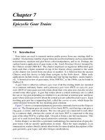
follows, we concentrate our study on the epicyclicgear type transmission mechanisms.
8.4.1 Functional Requirements
In a transmission mechanism, the term speed ratio is defined as the ratio of the
input shaft speed to the output shaft speed of the gear train. Various speed ratios are
obtained by engaging and disengaging clutches. The speed ratios of an automotive
transmission are tailored for vehicle performance and fuel economy. It should provide
a vehicle with several forward speeds, typically including a first gear for starting, a
second and/or third gear for passing, an overdrive for fuel economy at road speeds,
and a reverse. A table showing a sequence of speed ratios and the corresponding
clutching conditions is called a clutching sequence. Figure 8.8b shows the clutching
sequence of the epicyclic gear transmission depicted in Figure 8.8a, where an X
indicates that the corresponding clutch is engaged. We note that during speed ratio
changes, only one clutch is engaged while another is simultaneously disengaged. We
© 2001 by CRC Press LLC