Tài liệu High Performance Driver P1 ppt
Bạn đang xem bản rút gọn của tài liệu. Xem và tải ngay bản đầy đủ của tài liệu tại đây (120.81 KB, 9 trang )
HIGH PERFORMANCE DRIVES
---------------------------------------------------------------------------------------------------------------------------------------
E Levi, 2001
29
2.4.2. Voltage source inverter (VSI)
Variable voltage, variable frequency operation of induction machines is realised utilising autonomous
inverters, in conjunction with a rectifier and a DC link circuit. The voltage source inverter (VSI) is the
most frequently applied power supply source for speed control of induction motors. It can be operated in
six-step mode or in PWM mode. Six-step operation will be considered first.
Three-phase VSI contains three inverter legs. Input voltage for a three-phase VSI is provided by a three-
phase (or single-phase) bridge rectifier with capacitor placed at the output. The capacitor provides
smoothing of the DC voltage and, for sufficiently large capacitance, DC voltage at the rectifier output
approaches a constant value. It will therefore be assumed that inverter input voltage is constant in all the
subsequent analysis.
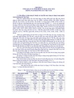
Power circuit of a voltage source inverter is shown in Fig. 2.13. As the inverter itself controls only the
frequency of the output voltage when operated with switching frequency equal to output fundamental
frequency (six-step mode), a controllable rectifier must be used in order to provide control of the output
voltage magnitude (output voltage magnitude is proportional to the input DC voltage). Each switch in
the inverter circuit is composed of two back-to-back connected semiconductor devices. One of these two
is a controllable switch, while the other one is a diode. The three inverter legs are controlled in such a
way that leg voltages constitute three-phase system of square-wave voltages. This means that, assuming
that upper transistor in leg A is fired at time instant zero, firing of upper transistor in leg B will take
place after 120 degrees, while firing of the upper transistor in leg C will be delayed for another 120
degrees. The conduction of each of the six semiconductor switches is again 180 degrees so that at any
time three out of six switches are on and the remaining three switches are off. The resulting output
voltage waveforms for line-to-line voltages are quasi-square waves, with two 60 degrees zero intervals
and two 120 degrees intervals in which line-to-line voltage equals plus and minus DC voltage,
respectively. VSI operated in the 180 degrees conduction mode is therefore usually called six-step
inverter. Leg voltages of the inverter are given in Fig. 2.14 with respect to the negative pole of the DC
link. Line-to-line voltages applied to the induction machine are obtained directly from leg voltages as
p
C
V
DC
ABC
n
IM
Rectifier and inverter control
Fig. 2.13 - Three-phase voltage source inverter (VSI) fed induction motor drive.
HIGH PERFORMANCE DRIVES
---------------------------------------------------------------------------------------------------------------------------------------
E Levi, 2001
30
v
An
V
DC
v
AB
V
DC
v
Bn
v
BC
v
Cn
v
CA
0 60 120 180 240 300 360
ωt[°]
Leg voltages
Line-to-line voltages
2/3 V
DC
v
a
1/3V
DC
v
b
Phase to neutral voltages
v
c
Fig. 2.14 - Leg, line-to-line and phase to neutral voltages in VSI fed induction machine.
v
AB
=v
An
-v
Bn
v
BC
=v
Bn
-v
Cn
(2.53)
v
CA
=v
Cn
-v
An
Line-to-line voltages are shown in Fig. 2.14 as well. Finally, if the machine is star connected, it can be
shown that in the system of Fig. 2.13 phase to neutral voltages of the machine (included in the Fig.
2.14) are determined with the following expressions:
()
()
()
vv vv
vv vv
vv vv
aAnBnCcn
bBnAnCn
cCnBnAn
=−+
=− +
=−+
23 13
23 13
23 13
//
//
//
(2.54)
HIGH PERFORMANCE DRIVES
---------------------------------------------------------------------------------------------------------------------------------------
E Levi, 2001
31
Let us consider now situation in a three-phase PWM voltage source inverter (VSI) with regard to space
vector theory. From the point of view of the distinct non-zero voltage values that can be obtained, there
is no difference between six-step VSI and a PWM VSI. A six-step VSI is therefore analysed. Power
circuit of the VSI and associated voltage wave-forms, valid for six-step operation, are those of Figs.
2.13 and 2.14. As can be seen From Fig. 2.14, change in any one of the three leg voltages takes place
after every sixty degrees. Leg voltages have constant values within sixty degrees intervals. Thus it
follows that the space vector of leg voltages will have six distinct and discrete values and that, instead of
uniformly rotating in the complex plane, it will be jumping from one position to the other.
Table 2.1 summarises values of leg voltages in the six sixty degrees intervals, lists switches that are on,
and defines a corresponding space vector for each interval. Apart from the six non-zero voltage space
vectors, that can be obtained in the six-step mode of operation, two additional vectors (no. 7 and 8) are
added at the bottom of the Table. These two vectors can be obtained only in PWM operation of the VSI
and they describe the condition when the induction motor terminals are short circuited either through the
positive rail of the dc supply (vector 7) or through the negative rail of the dc supply (vector 8).
Calculation of the leg voltage space vectors is rather simple. From the definition of the voltage space
vector in (2.28) one gets, by substituting individual leg voltages of Table 2.1 for each of the six sixty
degrees intervals, the following (note that stationary reference frame is considered at all times;
superscript ‘s’ is omitted):
()
vvavav a j a j
s
s
An Bn Cn
=++ = =
2
3
23 43
22
,exp( ) exp( )
ππ
(2.28)
() () ()
() () ()
vV vVj vVj
vVj vVj vVj
DC DC DC
DC DC DC
12 3
45 6
23 23 3 23 2 3
23 23 4 3 23 5 3
== =
== =
exp( /) exp( /)
exp( ) exp( / ) exp( / )
ππ
ππ π
(2.55)
Table 2.1 - Leg voltages
switching state switches on space vector Leg voltage v
An
Leg voltage v
Bn
Leg voltage v
Cn
1 1,4,6 v
1
V
DC
00
2 1,3,6 v
2
V
DC
V
DC
0
3 2,3,6 v
3
0V
DC
0
4 2,3,5 v
4
0V
DC
V
DC
5 2,4,5 v
5
00V
DC
6 1,4,5 v
6
V
DC
0V
DC
7 1,3,5 v
7
V
DC
V
DC
V
DC
8 2,4,6 v
8
000
The two remaining space vectors are identically equal to zero as either all the leg voltages are
zero or all the leg voltages have the same value (
10
2
++ =aa
). Hence
vv
78
0==
(2.56)
It follows from (2.55) that all the non-zero space vectors have identical amplitudes. However, they are
stationary, indicating that only discrete values of the leg voltage space vector are possible in a VSI. In
the six-step mode of operation transition from one space vector to the other takes place after each sixty
degrees interval (for 50 Hz output, after 3.33 ms). In the PWM mode of operation the non-zero values
remain to be given with (2.55). PWM mode adds two more possible vectors, called zero vectors, (2.56).
Additionally, transition from one vector to the other takes place at much higher frequency than the
HIGH PERFORMANCE DRIVES
---------------------------------------------------------------------------------------------------------------------------------------
E Levi, 2001
32
output frequency and each vector is utilised many times in creation of the output voltage of the given
frequency.
Distinct values of leg voltages (2.55) can be described with a single equation
()
()
vVjk
leg
DC
=−
é
ë
ê
ù
û
ú
23 1
3
exp
π
k = 1,2,3,4,5,6 (2.57)
For k =7andk = 8 leg voltage space vector equals zero. As can be seen from (2.57), time is not present
in this equation, confirming that the vector does not travel continuously in time. Frequency is not
present either, so that the rate at which certain vector value is applied will be governed by switching
frequency in the PWM VSI. Space vector values for the leg voltage are shown in Fig. 2.15.
Consider next line-to-line voltages at the output of the inverter, shown in Fig. 2.14. Table 2.2
summarises values of line-to-line voltages in different sixty degree intervals and again lists two more
states, obtainable in PWM mode only, when all the line-to-line voltages are zero. There are again six
non-zero values of the voltage space vector and two conditions that yield zero value of the voltage space
vector.
32
7,8
41Re(
α
)
56
Fig. 2.15 - Discrete values of the leg voltage space vector.
Table 2.2 - Line-to-line voltages
switching state switches on space vector Line-to-line
voltage v
AB
Line-to-line
voltage v
BC
Line-to-line
voltage v
CA
1 1,4,6 v
1L
V
DC
0
−V
DC
2 1,3,6 v
2L
0V
DC
−V
DC
3 2,3,6 v
3L
−V
DC
V
DC
0
4 2,3,5 v
4L
−V
DC
0V
DC
5 2,4,5 v
5L
0
−V
DC
V
DC
6 1,4,5 v
6L
V
DC
−V
DC
0
7 1,3,5 v
7L
000
8 2,4,6 v
8L
000
Space vector of line-to-line voltages is again calculated using the definition of the space vector,
(2.28). Substitution of individual line-to-line voltages into (2.28) for each of the six sixty degrees
intervals produces the following result:
HIGH PERFORMANCE DRIVES
---------------------------------------------------------------------------------------------------------------------------------------
E Levi, 2001
33
() ()
() ()
() ()
vVj vVj
vVj vVj
vVj vVj
L
DC
L
DC
L
DC
L
DC
L
DC
L
DC
12
34
5
6
23 3 6) 23 3 2
23 3 5 6) 23 3 7 6)
2 3 3 3 2 2 3 3 11 6)
==
==
==
exp( / exp( / )
exp( / exp( /
exp( / ) exp( /
ππ
ππ
ππ
(2.58)
Space vector of line-to-line voltages is again equal to zero in states 7 and 8,
vv
LL
78
0==
(2.59)
Line-to-line voltages are therefore characterised with six discrete values, whose amplitude is √3larger
than for the leg voltages, and they are shifted in phase by 30 degrees with respect to the corresponding
values of the leg voltage space vector. Values of the line-to-line voltage space vector are shown in Fig.
2.16.
Space vector of line-to-line voltages, whose discrete values are given in (2.58), can be described with an
expression similar to (2.57)
()
vVjk
L
DC
=−
é
ë
ê
ù
û
ú
2
3
321
6
exp
π
k = 1,2,3,4,5,6 (2.60)
For k =7andk = 8 line-to-line voltage space vector equals zero. As expected, (2.60) is independent of
time. Hence the time interval during which the space vector remains in one position is determined with
the inverter switching frequency.
2
37,8 1
Re (
α
)
46
5
Fig. 2.16 - Discrete values of the line-to-line voltage space vector.
Finally, let us consider phase to neutral voltages of the motor, whose wave-forms are given in Fig. 2.14.
Table 2.3 summarises values of phase to neutral voltages for the six sixty degrees intervals.
Table 2.3 - Phase to neutral voltages
switching state switches on space vector Phase voltage v
a
Phase voltage v
b
Phase voltage v
c
1 1,4,6 v
1phase
(100) (2/3)V
DC
-(1/3)V
DC
-(1/3)V
DC
2 1,3,6 v
2phase
(110) (1/3)V
DC
(1/3)V
DC
-(2/3)V
DC
3 2,3,6 v
3phase
(010) -(1/3)V
DC
(2/3)V
DC
-(1/3)V
DC
4 2,3,5 v
4phase
(011) -(2/3)V
DC
(1/3)V
DC
(1/3)V
DC
5 2,4,5 v
5phase
(001) -(1/3)V
DC
-(1/3)V
DC
(2/3)V
DC
6 1,4,5 v
6phase
(101) (1/3)V
DC
-(2/3)V
DC
(1/3)V
DC