Tài liệu High Performance Driver P5b docx
Bạn đang xem bản rút gọn của tài liệu. Xem và tải ngay bản đầy đủ của tài liệu tại đây (116.21 KB, 7 trang )
HIGH PERFORMANCE DRIVES
---------------------------------------------------------------------------------------------------------------------------------------
E Levi, 2001
56
v
qs
*
v
ds
e
φ
r
j
ω
φ
r
i
i
i
a
b
c
*
v
v
*
*
α
β
s
s
v
qs
'
v
ds
'
-
i
ds
*
qs
i
*
ω
*
-
ω
P+I
-
P+I
P+I
i
ds
*
i
qs
*
ω
r
*
L
s
L
σ
s
qs
i
ds
i
-
+
e
-j φ
r
2
3
VOLTAGE
SOURCE
PWM
INVERTER
T
r
i
ds
*
1 ω
sl
*
ω
r
*
+
+
INDUCTION
MACHINE
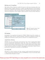
Fig. 3.12 - Indirect (feed-forward) voltage fed rotor flux oriented induction machine.
3.4. PERFORMANCE OF A ROTOR FLUX ORIENTED INDUCTION MACHINE
Some characteristic simulation and experimental results are given in this Section, that illustrate
behaviour of rotor flux oriented induction machines. Current-fed indirect rotor flux oriented machine is
discussed at all times. Both the scheme of Fig. 3.11 with indirect vector control and the scheme of Fig.
3.9 with direct vector control are under consideration.
Consider at first the scheme of Fig. 3.9. Simulation results are presented in what follows. Rated rotor
flux reference is applied at time instant zero. Speed reference and the load torque are equal to zero.
Once when the rotor flux is established, a speed reference is applied. The simulation results are given in
Fig. 3.13. As can be seen from Fig. 3.13, the initial excitation of the machine follows exponential law.
When the flux settles and speed command is applied, actual speed follows reference speed with a very
small delay, caused by inertia of the drive. Torque rises almost instantaneously and reaches the
maximum value determined by the imposed limit and hence the stator current is in the limit as well.
Note that rotor flux remains constant during the torque variation, indicating that flux and torque control
are fully decoupled (change of stator q-axis current does not cause any variation in the rotor flux).
When the reference speed reaches steady-state value the actual speed overshoots (due to action of the
speed controller, which is PI) and hence torque rapidly goes out of the limit, reduces and becomes
negative, which means that electric braking operation takes place. Once when the speed settles at the
value equal to the reference value, torque falls to zero, because the case shown in Fig. 3.13 is
acceleration with zero load torque. Comparison of Fig. 3.13 with Fig. 1.4 shows that the responses are
identical: hence the rotor flux orientation control successfully converts an induction machine into its DC
machine equivalent.
Direct rotor flux oriented current fed induction machine of Fig. 3.9 is simulated again. CRPWM
inverter is taken as ideal so that commanded stator phase currents are directly impressed into the motor
stator phase windings. Once more, the machine is at first excited with rated rotor flux command. Once
when the rotor flux is established in the machine, speed command equal to −40 % of the rated speed is
HIGH PERFORMANCE DRIVES
---------------------------------------------------------------------------------------------------------------------------------------
E Levi, 2001
57
applied through a rate-of-change limiter. Load torque equals zero throughout the transients. A steady-
state, similar to the one of Fig. 3.13, is established. The subsequent simulation, illustrated in Fig. 3.14,
involves so called reversing transient: speed reference is changed from −40 %
torque limit
T
e
ψ
r
0
ψ
r
ω
*
ω
0time
Fig. 3.13 - Dynamic behaviour of current-fed direct rotor flux oriented induction machine:
Initial excitation and rapid acceleration in the constant flux region.
0
0.2
0.4
0.6
0.8
1
Rotor flux (Wb)
-200
-100
0
100
200
300
Rotor angular speed (rad/s)
0 0.01 0.02 0.03 0.04 0.05
Time (s)
ψ
ψψ
ψ
ψ
ψψ
ψ
ψ
ψψ
ψ
e
r
*
r
r
ω
ωω
ω
ω
ωω
ω
*
=
-40
-30
-20
-10
0
10
20
30
40
Torque (Nm)
-5
0
5
10
15
20
25
30
35
Stator current components (A)
0 0.01 0.02 0.03 0.04 0.05
Time (s)
e
ds
i
e
qs
e
e
e
T
,T
=i
i
=i
*
qs
*
ds
Fig. 3.14 - Reversing transient of the drive of Fig. 3.9.
HIGH PERFORMANCE DRIVES
---------------------------------------------------------------------------------------------------------------------------------------
E Levi, 2001
58
to +40% of the rated speed in a ramp-wise manner. Simulation results, summarised in Fig. 3.14, depict
rotor flux reference, actual rotor flux and estimated rotor flux (superscript ‘e’ denotes estimated values),
actual and estimated torque, actual and commanded speed, and actual and estimated stator current d-q
axis components. Excellent dynamic behaviour is evident. The actual flux in the machine remains
constant during the reversing transient, indicating that the variation of the stator q-axis current does not
affect the rotor flux. Flux and torque control are therefore fully decoupled. The drive operates for a
prolonged period of time in the torque limit (and hence in the current limit as well) during the reversing.
Once when the new operating speed is established, torque falls to zero since the reversing is simulated
under no-load conditions.
As the last simulation example of the scheme of Fig. 3.9, step loading and unloading of the drive is
investigated. The drive operates initially in steady-state with zero load torque and with constant value of
speed and rotor flux. Step load torque, equal to the rated value, is then at first applied and then
removed. Rotor flux and motor torque are shown in Fig. 3.15. Torque build-up is extremely quick. The
torque initially overshoots the load torque in order to compensate the speed dip caused by the load
torque application. Speed is returned to the previous steady-state value and the motor torque equals load
torque until the load torque removal takes place. Torque of the motor quickly goes down and becomes
negative for a very short period of time in order to compensate for the increase in the speed caused by
the load torque removal. Once when the speed is returned to its previous value, torque becomes equal to
zero. Rotor flux remains completely undisturbed during these transients, indicating once more fully
decoupled rotor flux and torque control.
Fig. 3.15 - Response of the drive of Fig. 3.9 to step loading and unloading.
Indirect rotor flux oriented induction motor drive of Fig. 3.11 is investigated next. A series of
experiments is performed on a commercially available drive (manufactured by Vickers company) and
some of these are presented in what follows. However, before depicting the transient behaviour, let us at
first illustrate the current waveform in steady-state operation. Fig. 3.16 shows recorded phase current
waveform and its spectrum. Obviously, the current is not an ideal sine wave. However, all the higher
harmonics are of very high frequency and are situated around multiples of the 10 kHz frequency, which
is the switching frequency of the inverter. The CRPWM inverter thus enables approximate satisfaction
of the condition (3.1), as already noted in the beginning of this Chapter.
Acceleration transient is investigated next. The machine initially operates at 200 rpm. A speed
command of 1500 rpm is then applied, under no-load conditions. The motor speed and the phase current
are shown in Fig. 3.17. As can be seen, current quickly goes into the limit and stays in the limit until the
motor speed approaches the set speed. The speed slightly overshoots the reference, leading to the
braking action of the motor. Once when the acceleration transient is over, motor phase current becomes
equal to the magnetising current of the machine (i.e., neglecting losses, stator q-axis current is zero and
the phase current is equal to the stator d-axis current which is the magnetising current).
HIGH PERFORMANCE DRIVES
---------------------------------------------------------------------------------------------------------------------------------------
E Levi, 2001
59
-8
-6
-4
-2
0
2
4
6
8
Current (A)
0 0.005 0.01 0.015
Time (s)
a. current waveform
0.001
0.01
0.1
1
10
Current (A)
0 2 4 6 8 10 12
Frequency (kHz)
b. spectrumupto12.8kHz
0.001
0.01
0.1
1
10
Current (A)
0 100 200 300 400 500 600 700 800
Frequency (Hz)
c. spectrum up to 0.8 kHz
Fig. 3.16 - Current waveforms and spectra
during no-load operation at 2100 rpm.
Fig. 3.17 - Acceleration transient of an indirect rotor flux oriented induction machine.
As the next example, deceleration transient is investigated. The previous steady-state is the one of Fig.
3.17 (1500 rpm) and speed command is now stepped down to 200 rpm. Stator phase current and speed
are illustrated in Fig. 3.18. Note that the phase current goes in the limit again, indicating that the motor
is developing the maximum permitted torque, but now of negative value (braking action). The speed
quickly reduces and once when it becomes equal to the set value, stator current returns to its previous
(magnetising current) value.
Finally, Fig. 3.19 shows an experimental result obtained again with indirect rotor flux oriented current
fed induction machine. Stator d-axis current command is set to 70 % of the rated value so that machine
operates with 70 % of the rated flux (the reason for operation with reduced flux is beyond the scope of
HIGH PERFORMANCE DRIVES
---------------------------------------------------------------------------------------------------------------------------------------
E Levi, 2001
60
interest here). Speed command equals 600 rpm and is constant. Step loading and later on unloading is
applied, with load torque equal to the machine’s rated torque. Speed response and commanded stator q-
axis current are shown in Fig. 3.19. Fast build-up of the torque and consequently very fast recovery of
the speed with relatively very small drop and subsequent increase during the transients can be observed
in Fig. 3.19.
Fig. 3.18 - Deceleration transient of an indirect rotor flux oriented induction machine.
Fig. 3.19 - Experimentally recorded speed and commanded q-axis current response to step loading
and unloading of an indirect rotor flux oriented current fed induction machine.
3.5. PARAMETER VARIATION EFFECTS IN ROTOR FLUX ORIENTED INDUCTION
MACHINES
As is obvious from the considerations of rotor flux oriented control principles, all the methods of rotor
flux position estimation, as well as rotor flux amplitude and torque estimation, heavily rely on
mathematical model of the induction machine. The model assumes that all the parameters are constant
and accurately known. Discrepancy between parameter values utilised in an estimator and actual
parameter values in the machine leads to incorrect rotor flux space vector estimation and erroneous
orientation of stator current space vector results.