ACB SS (old model) catalogue
Bạn đang xem bản rút gọn của tài liệu. Xem và tải ngay bản đầy đủ của tài liệu tại đây (2.04 MB, 68 trang )
ADVANCED AND EVER ADVANCING
Mitsubishi Low Voltage Air Circuit Breaker
AE-SS AE-SH
ISO 9001
Mitsubishi Electric Corporation's Fukuyama Works,
which produces these products, is certified as meeting
the ISO 14001 environmental management system standard.
NATIONAL
ACCREDITATION
OF CERTIFICATION
BODIES
00
B
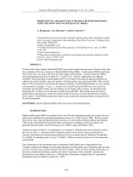
With the highly advanced information
technologies, dependability as well as safety
and ease of handling of the electrical power
supply are ever-growing requirements. The
recent introduction of systemized and intelligent
buildings, upgrading, and space-saving, and
severe safety standard of power distribution has
become a major subject within the electrical
power supply industry. To cope with all these
circumstances, Mitsubishi now presents the
Super AE series Low Voltage Air
Circuit Breakers.
1
Contents
s Features
Main unit features ...........................................3~4
Electronic trip relay features ............................5~8
s External view and
Internal construction ..................................9~10
s Product introduction ...........................11~12
s Product specification
Specification<IEC60947-2 Ics/Icu> .............13~14
Specification
<JIS C8372, Shipping standard> ....................15~16
s Connecting methods ................................17
s Charging methods......................................18
s Accessories
For breaker unit ...........................................19~22
For drawout frame .......................................23~24
s Electronic trip relay
Specification table .......................................25~26
General use (S type) ...................................27~28
Generator protection use (M type) ..............29~30
Special use (B type) ....................................31~32
Electronic trip relay accessories..................33~35
Circuit diagram of the electronic trip relay .........36
s Operating Characteristics
General use (S type) .........................................37
Generator protection use(M type) .....................38
Special use (B-C0 type) ....................................39
s Tripping characteristics setting
Setting procedure ..............................................40
How to adjust the trip Relay ........................41~44
s Wiring Diagram .....................................45~46
s Outline Dimensions
Draw-out type ..............................................47~51
Fixed type ....................................................52~54
Panel cut, drawout handle, terminal adapter .....55
Neutral CT, External ZCT ..................................56
s Technical information .........................57~62
s Ordering information
General use (Example) .....................................63
General use (S type) .........................................64
Generator protection use (M type) ....................65
2
s Main unit features
Easier Operation
Plenty Type Composition
s The addition of 4000A, 5000A and 6300A frame to the universal series makes applicable
for a wide range of types from 630A to 6300A.
s The addition of high breaking capacity (AE-SH) series (630A-3200A frame) has enabled
the design of economic sequences.
Expanded selective interruption range
s With the increased short-time current rating, the selective interruption range can be
expanded with the use of the electronic trip relays with MCR function.
AE630-SS ~ AE3200-SS 65kA
AE4000-SSC 75kA
AE4000-SS
AE5000-SS 85kA
AE6300-SS
Full moulding
s Since the breaker is fully insulated with mouldings, it is safe to use for a wide range of
applications.
Long service life
s 10,000 mechanical open/close operations for all types. (Except for AE4000-SS~AE6300-SS,
AE4000-SSC)
Zero arc space
s Arc exhaust space to the outside of the breaker is drastically reduced for safer operation.
(AE630-SS ~ AE3200-SS, AE4000-SSC q 600VAC)
Reverse connection available
s Line and Load is not defined on the Main circuit terminals.
Therefore reverse connection is available without any limitation.
3
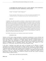
More complete New AE4000-SSC
sThe new AE4000-SSC which is smaller and economical makes fill up the AE-SS series.
DRAWOUT TYPE 3P
875
240kg
58%
(volume ratio)
8
36
AE4000-SSC
DRAWOUT TYPE 3P
565
61%
430
AE4000-SS
480
sAE4000-SSC has realized smaller and lighter than AE4000-SS.
8
36
145kg
(weight ratio)
sNumber of Operating cycles has been increased (2000 cycles→5000 cycles).
note 1: Only 3-pole type is available.
note 2: The Max. rated current is 3600A on JIS C8372.
4
s Electronic trip relay features (1/2)
Multi functions available
1 Electronic trip relay series
Grouped electronic trip relays for
easier selection
Application
Measuring
& Display
Communication
Relay type
Remarks
US3
Provides CC-Link communication, data
measuring and display for adaption to
networking systems.
Function
US3 type
•
General
use
S
S, M type
A multi-function type that provides all the
characteristics required for the main
circuit.
•
B-C0A
•
Generator
protection
use
M
Special
use
B-C0A
Provided with characteristics for protecting
generators for private power generation
and marine vessels.
INST/MCR
characteristics
•
•
Multi-function
L, S, I/MCR
characteristics
Ground fault/
Earth leakage
protection
Trip indicator
•
•
Plenty of electrical data
is measured and
displayed
Measured data,
alarm and setting value
is transmitted on
CC-Link bus line
Remote ON/OFF operation
Only INST/MCR characteristics is provided.
q Meets with a wide range of need depending on the application.
q Contributes to selective co-ordination, and ensures fine characteristic setting.
2 Common features
Opt
ion
Pre-alarm function (PAL)
The load current exceeds the value of the setting, before the breaker trips, the PAL
operates, it contributes electrical continuity and easy maintenance.
Opt
ion
Trip indicator (TI)
The trip indicator (TI) is operated simultaneously with the OCR alarm (AL), when the
breaker trips because of Long time delay, short time delay/Instantaneous and Ground fault
or Earth leakage. The relavent cause of tripping will be displayed on the appropriate
indication LED and a relay contact will provide an output signal.
Opt
ion
Temperature alarm (TAL)
The TAL is operated by an unusual temperature of the breaker contacts.
Opt
ion
Earth leakage protection (ER)
A choice of earth leakage alarm or earth leakage tripping function is available improving
the discrimination and the safety in circuit design.
5
Meets Many Needs
Overcurrent protection on the
neutral pole (NP)
In a 3-phase 4-wire circuit such that as provided to a computer, DC power unit or other
load devices, higher harmonics are liable to be generated which could cause damage as
more load current flows in the neutral plole.
NP will eliminate such a possibility.
More secure protection owing to
detection of effective value (RMS)
Effective value detection that is most suitable for the protection of electronic devices.
Effective value detection independently provided for each phase, which is effective for
distorted wave forms, is used to cope with the increasing use of electronics devices,
including inverters.
Distorted current
AC/DC
Effective value conversion
Maximum phase selection
Over Current
protection
(LTD circuit)
Sine wave current
Opt
ion
Ground fault protection (GFR)
Either a ground fault trip or alarm function can be selected by a change-over switch.
A control supply is not necessary.
Load current indication LEDs
The load current can be easily checked with the indication LEDs on the electronic trip
relay.
6
s Electronic trip relay features (2/2)
MDU (Measuring Display
Available for AE630-SS~AE6300-SS
The full line up through MCCB 400A to ACB 6300A enables measurements
display and transmission of electric circuit information.
MDU relay types
Type
Characteristics
US3P
LTD+STD+INST/MCR
US3G
LTD+STD+INST/MCR+GFR
US3E
LTD+STD+INST/MCR+ER
Transmission
CC-Link
MDU Display unit
PAL and AL are standard function
AE-SS MDU
1Electronic trip relay (US3P etc.)
2MDU display unit
nterface unit
3CC-Link!
Measurement functions
Measured items
(accuracy)
Load current
(±2.5%)
Contents
Present value (I1, I2, I3, IN )
Demand value (I1, I2, I3, IN )
Maximum demand value (max. phase)
Line voltage
(±2.5%)
Present value (V1-2, V2-3, V3-1)
Demand value (V1-2, V2-3, V3-1)
Maximum demand value (max. phase)
Phase voltage
(±2.5%)
Present value (V1-N, V2-N, V3-N)
Demand value (V1-N, V2-N, V3-N)
Harmonics
(±2.5%)
Present value at 3rd, 5th, 7th (I1, I2, I3, IN )
Maximum value at 3rd, 5th, 7th (max. phase)
Present value of total harmonics (I1, I2, I3, IN )
Demand value of total harmonics (I1, I2, I3, IN )
Maximum demand value of harmonics (max. phase)
Power
(±2.5%)
Present value
Demand value
Maximum demand value
Electric energy
(±2.5%)
Energy (accumulated value)
Time electric energy
Maximum time electric energy
Reactive power
(±2.5%)
Present value
Demand value
Maximum demand value
Reactive energy
(±2.5%)
Reactive energy (accumulated value)
Time electric energy
Maximum time electric energy
Present value
Power factor
(±5%)
Present value
Frequency
In case of 4P AE-SS, IN and phase voltage measuring are available.
7
CC-Link Interface unit
AE1600-SS with MDU
Unit) lineup for AE-SS
Transmission items
Incorporation of transmission function
Function
Remote
monitoring
Input
Output
Contents
Measured data (refer to page 7)
Circuit condition (PAL pickup, PAL OUT, OVER)
Fault information (Trip cause & Trip current)
Setting of the Electronic trip relay (! ,! , TL,! ...)
n
p
sd
Demand time setting
Data clear (Accumulated data, Fault information)
Error (Measuring, Transmission)
AE-SS ON/OFF status (by AXa) and other two “a” contact inputs
For remote ON/OFF
PLC networking
The CC-Link transmission facilitates networking with high level systems (such as SCADA)
via PLC
Specifications for CC-Link transmission
Item
Specifications
Transmission speed
Selection from among 156kbps/625kbps/2.5Mbps/5Mbps/10Mbps
Connection system
Broadcast polling
Number of connectable unit per system
Max. 42unit
Maximum transmission distance
Max. 1200m (156kbps, when using a dedicated cable)
Unit type
Remote device station
(station which can transmit word data as well as input/output)
Number of exclusive station
1 station
Server
or
PC
System bus
MELSEC series PLC
Example of the PC monitoring
CC-Link
CC-Link master unit
CC-Link
Interface
unit
MDU breaker
AE-SS MDU
8
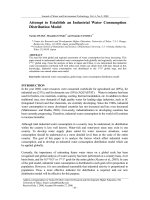
s External view and Internal construction
Fixed type
Arc extinguishing chamber
AE-SS Series
Control circuit terminal block
Electronic trip relay
OFF button
ON button
Padlock position
Charging handle
Charging indicator
ON/OFF indicator
Lifting hooks (HP) is supplied in the case of a fixed type AE-SS series.
AE1600-SS 3P
Drawout type
AE-SS Series
Cradle
Automatic control circuit connector
Lifting hole
Charging handle
Extention rail
Drawout position indication
Position lock
Aperture for the drawout handle
Drawout handle
AE1600-SS 3P
9
Drawout type
AE-SH Series
Control circuit terminal
Cradle
Automatic control circuit connector
Charging handle
Drawout position indication
Fixing bolt
Extension rail
Position lock
Aperture for the drawout handle
Drawout handle
AE3200-SH 3P
Internal Construction
AE-SS Series
q Control circuit terminal block
w Automatic control circuit connector
e Auxiliary switches
r Shunt trip device, Closing coil
t Electronic trip relay
y Front Cover
u Tripping mechanism
i Closing mechanism
o Charging mechanism
!0 Closing spring
!1 Draw-out mechanism
!2 Insulated base
!3 Arc extinguishing chamber
!4 Main movable contacts
!5 Main fixed contacts
!6 Conductors on the breaker
!7 Conductors on the cradle
!8 Main circuit junction
!9 Base
@0 Contact spring
@1 Conductors on the breaker
@2 Conductors on the cradle
@3 Power supply CT
@4 Current sensor coil
@5 Cradle
10
s Product introduction
Super AE series allows easier
customer selection
2
1
Type
Page
AE630-SS
AE1000-SS
AE1250-SS
AE1600-SS
AE2000-SS
Standard
AE2500-SS
model
AE3200-SS
AE4000-SSC
AE4000-SS
AE5000-SS
AE6300-SS
3
Standard
Page
Connecting
method
Horizontal
terminals
IEC 60947-2
BS EN 60947-2
VDE 0660
Vertical
terminals
JIS C8372
JIS C8370
13~16
13~16
Shipping standard
Front
terminals
LR
GL
AE1000-SH
DNV
AE1250-SH
AB
High
breaking AE1600-SH
model AE2000-SH
BV
Fixed type
NK
AE2500-SH
AE3200-SH
Electromagnetic Compatibility
Description
Standard
test procedure
Conducted RF disturbances
EN55011:1991 (Class A, Group 1)
Radiated RF disturbances
EN55011:1991 (Class A, Group 1)
Electrostatic discharge
IEC61000-4-2 (contact Level 4)
Emission
Electromagnetic field
IEC60947-2 IEC61000-4-3 (Level 3)
Fast transients / burst
IEC61000-4-4 (Level 4)
Surge
IEC61000-4-5 (Level 4)
Conducted radio frequency
IEC61000-4-6 (Level 3)
Earthleakage protection is not applicable for these tests.
11
Cradle
Cell switch
Shorting-B contact
Lifting hooks
Safety shutter
Safety shutter lock
Mis-insertion
preventor
Test jumper
Draw-out type
AE630-SH
Immunity
Page
17
Page
23, 24
4
5
Accessories
Page
Auxiliary switch
Motor charging device
Electrical
accessories
Closing coil
18~20, 22
Shunt trip device
Under voltage trip device
Condenser trip device
Electronic
trip relay
Page
General use:
• S type
Generator
protection use
• M type
Special use
• B-C0A type
25~32
Relay accessories
Trip indicator
Ground fault
protection
Earth leakage
protection
Pre-alarm
OCR-alarm
Temperature alarm
Page
33, 34
Push button cover
Counter
Mechanical
accessories
Cylinder lock
Door interlock
Terminal cover
Door frame
Dust cover
21, 22
General use:
• US3 type
Data Meauring
Display (MDU)
with CC-Link
communication
Neutral CT
External ZCT
Field test device
7, 8
34, 35
Interphase barrier
Mechanical interlock
6
Special
environment
Page
Moisturefungus
treatment
Extracorrosion
proof
specifications
58
Terminal adapter Page
Vertical terminal
adapter
17, 55
Front terminal
adapter
12
s Product Specification
q Specification
SS type (standard model)
Type
Frame size
Rated insulation voltage
Rated operating voltage
Number of poles
Rated current (!n)
(A)
(A)
(VAC)
(VAC)
(P)
General use
(Current rating adjustable)
Generator protection use
(Current rating fixed)
Drawout type Fixed type
b
b
(A)
690VAC
600VAC
With instantaneous trip
500VAC
Rated
240VAC
breaking
690VAC
capacity
600VAC
! !
cs/ cu
With MCR
500VAC
(RMS kA)
240VAC
690VAC
Without instantaneous (Note2)
500VAC
690VAC
600VAC
With instantaneous trip
500VAC
Rated
240VAC
making
690VAC
capacity
600VAC
C
!m
With MCR
500VAC
(Peak kA)
240VAC
690VAC
Without instantaneous (Note2)
500VAC
1s
Rated short time current !
cw
2s
(RMS kA)
3s
Maximum total breaking time
(s)
(s)
Closing time
With rated current
Number of operating cycles. (Note 1)
Without rated current
a
b
c
a
c
d
d
a
b
c
a
c
d
d
Manual charging type
Fixed type
Motor charging type
Weight
Manual charging type
Drawout type
(kg)
(including cradle)
Motor charging type
Cradle only
Outline dimension (mm)
Rated current of neutral pole
AE630-SS
630
1000
690
3
4
AE1000-SS
1000
1000
690
3
4
AE1250-SS
1250
1000
690
3
4
AE1600-SS
1600
1000
690
3
4
AE2000-SS
2000
1000
690
3
4
AE2500-SS
2500
1000
690
3
4
AE3200-SS
3200
1000
690
3
4
315-378-441
-504-567-630
625-750-875 800-960-1120
250-300-350 500-600-700
-400-450-500 -800-900-1000 -1000-1125-1250 -1280-1440-1600
157-189-220
-252-284-315
1000-1200-1400
-1600-1800-2000
800-960-1120 1250-1500-1750 1600-1920-2240
-1280-1440-1600 -2000-2250-2500 -2560-2880-3200
625-750-875
-1000-1125-1250
200 q n q 630
!
500 q n q 1000
!
625 q n q 1250
!
800 q n q 1600
!
625 q n q 2000 1250 q n q 2500 1600 q n q 3200
!
!
!
630
50/50
50/50
65/65
65/85
42/42
50/50
65/65
65/65
25/25
25/25
105
105
143
187
88.2
105
143
143
52.5
52.5
65
40
30
0.04
0.08
5000
10000
340 425
410 410
290 290
38
38
300 385
430 430
368 368
61
61
40
50
43
53
63
77
66
80
26
30
1000
50/50
50/50
65/65
65/85
42/42
50/50
65/65
65/65
25/25
25/25
105
105
143
187
88.2
105
143
143
52.5
52.5
65
40
30
0.04
0.08
5000
10000
340 425
410 410
290 290
38
38
300 385
430 430
368 368
61
61
41
51
44
54
64
78
67
81
26
30
1250
50/50
50/50
65/65
65/85
42/42
50/50
65/65
65/65
25/25
25/25
105
105
143
187
88.2
105
143
143
52.5
52.5
65
40
30
0.04
0.08
5000
10000
340 425
410 410
290 290
38
38
300 385
430 430
368 368
61
61
41
51
44
54
64
78
67
81
26
30
1600
50/50
50/50
65/65
65/85
42/42
50/50
65/65
65/65
25/25
25/25
105
105
143
187
88.2
105
143
143
52.5
52.5
65
60
50
0.04
0.08
5000
10000
340 425
410 410
290 290
38
38
300 385
430 430
368 368
61
61
42
52
45
55
65
79
68
82
26
30
2000
50/65
65/65
85/85
85/85
50/50
65/65
65/65
65/65
45/45
45/45
143
143
187
187
105
143
143
143
94.5
94.5
65
65
65
0.04
0.08
1500
10000
475 605
410 410
290 290
38
38
435 565
430 430
368 368
61
61
60
72
63
75
92
113
95
116
35
43
2500
50/65
65/65
85/85
85/85
50/50
65/65
65/65
65/65
45/45
45/45
143
143
187
187
105
143
143
143
94.5
94.5
65
65
65
0.04
0.08
1500
10000
475 605
410 410
290 290
38
38
435 565
430 430
368 368
61
61
61
73
64
76
93
114
96
117
35
43
3200
50/65
65/65
85/85
85/85
50/50
65/65
65/65
65/65
45/45
45/45
143
143
187
187
105
143
143
143
94.5
94.5
65
65
65
0.04
0.08
1000
10000
475 605
410 410
290 290
38
38
435 565
430 430
368 368
61
61
63
75
66
78
95
116
98
119
36
44
Note 1 : The number of operating cycles without rated current also include the number of operating cycles with rated current.
Note 2 : The columns for “without instantaneous tripping” are the values when the bare (without electronic trip relay) main body and the
external relay are combined. Please apply for further detail.
13
VDE0660 Ics/Icu>
SH type (High breaking model)
AE4000-SSC AE4000-SS
4000
4000
1000
1000
690
690
3
4
3
3200-3600-4000
AE5000-SS
5000
1000
690
3
4
AE6300-SS
6300
1000
690
3
4
AE630-SH
630
1000
690
3
4
AE1000-SH
1000
1000
690
3
4
AE1250-SH
1250
1000
690
3
4
AE1600-SH
1600
1000
690
3
4
AE2000-SH
2000
1000
690
3
4
AE2500-SH
2500
1000
690
3
4
AE3200-SH
3200
1000
690
3
4
800-960-1120 1000-1200-1400 1250-1500-1750 1600-1920-2240
2000-2400-2800 2500-3000-3500 3150-3780-4410 315-378-441 500-600-700 625-750-875
-3200-3600-4000 -4000-4500-5000 -5040-5670-6300 -504-567-630 -800-900-1000 -1000-1125-1250 -1280-1440-1600 -1600-1800-2000 -2000-2250-2500 -2560-2880-3200
3200 q n q 4000 2000 q n q 4000 2500 q n q 5000 3150 q n q 6300 315 q n q 630 500 q n q 1000 625 q n q 1250 800 q n q 1600 1000 q n q 2000 1250 q n q 2500 1600 q n q3200
!
!
!
!
!
!
!
!
!
!
!
–
50/50
65/65
85/85
85/85
50/50
65/65
75/75
75/75
45/45
45/45
105
143
187
187
105
143
165
165
94.5
94.5
75
65
65
0.04
0.08
500
5000
605
414
290
136
565
430
368
151
109
112
145
148
75
3200
50/50
85/85
130/130
130/130
50/50
85/85
85/85
85/85
50/50
65/65
105
187
286
286
105
187
187
187
105
143
85
70
70
0.05
0.08
500
2000
873 1003
414 414
290 290
136 136
875 1005
480 480
368 368
123 123
160 180
164 184
240 263
244 267
125 140
3200
50/50
85/85
130/130
130/130
50/50
85/85
85/85
85/85
50/50
65/65
105
187
286
286
105
187
187
187
105
143
85
70
70
0.05
0.08
500
2000
873 1003
414 414
290 290
136 136
875 1005
480 480
368 368
123 123
160 180
164 184
240 263
244 267
125 140
3200
50/50
85/85
130/130
130/130
50/50
85/85
85/85
85/85
50/50
65/65
105
187
286
286
105
187
187
187
105
143
85
70
70
0.05
0.08
500
2000
873 1003
414 414
290 290
136 136
875 1005
480 480
368 368
123 123
160 180
164 184
240 263
244 267
125 140
630
65/65
85/85
130/130
130/130
–
–
–
–
–
–
65/65
85/85
130/130
130/130
–
–
–
–
–
–
–
–
–
0.04
0.08
3000
10000
475 605
410 410
290 290
68
68
485 615
430 430
398 398
61
61
66
79
69
82
105 127
108 130
42
50
1000
65/65
85/85
130/130
130/130
–
–
–
–
–
–
65/65
85/85
130/130
130/130
–
–
–
–
–
–
–
–
–
0.04
0.08
3000
10000
475 605
410 410
290 290
68
68
485 615
430 430
398 398
61
61
66
79
69
82
105 127
108 130
42
50
1250
65/65
85/85
130/130
130/130
–
–
–
–
–
–
65/65
85/85
130/130
130/130
–
–
–
–
–
–
–
–
–
0.04
0.08
3000
10000
475 605
410 410
290 290
68
68
485 615
430 430
398 398
61
61
66
79
69
82
105 127
108 130
42
50
1600
65/65
85/85
130/130
130/130
–
–
–
–
–
–
65/65
85/85
130/130
130/130
–
–
–
–
–
–
–
–
–
0.04
0.08
2000
10000
475 605
410 410
290 290
68
68
485 615
430 430
398 398
61
61
66
79
69
82
105 127
108 130
42
50
2000
65/65
85/85
130/130
130/130
–
–
–
–
–
–
65/65
85/85
130/130
130/130
–
–
–
–
–
–
–
–
–
0.04
0.08
1500
10000
475 605
410 410
290 290
68
68
485 615
430 430
398 398
61
61
66
79
69
82
105 127
108 130
42
50
2500
65/65
85/85
130/130
130/130
–
–
–
–
–
–
65/65
85/85
130/130
130/130
–
–
–
–
–
–
–
–
–
0.04
0.08
1500
10000
475 605
410 410
290 290
68
68
485 615
430 430
398 398
61
61
66
79
69
82
105 127
108 130
42
50
3200
65/65
85/85
130/130
130/130
–
–
–
–
–
–
65/65
85/85
130/130
130/130
–
–
–
–
–
–
–
–
–
0.04
0.08
1000
10000
475 605
410 410
290 290
68
68
485 615
430 430
398 398
61
61
68
81
71
84
107 129
110 132
43
51
14
s Product Specification
q Specification <JIS C 8372 (o-co-co duty)>
Type
Type
Frame size
Rated insulation voltage
Rated operating voltage
Number of poles
SS type (standard model)
(A)
(VAC)
(VAC)
(P)
Rated current ( n)
!
General use
(Current rating adjustable)
(A)
Generator protection use
(Current rating fixed)
AE630-SS
630
600
550
3
4
AE1000-SS
1000
600
550
3
4
AE1250-SS
1250
600
550
3
4
AE1600-SS
1600
600
550
3
4
315-378-441
-504-567-630
625-750-875 800-960-1120
250-300-350 500-600-700
-400-450-500 -800-900-1000 -1000-1125-1250 -1280-1440-1600
157-189-220
-252-284-315
200 q n q 630
!
500 q n q 1000
!
625 q n q 1250
!
800 q n q 1600
!
AE2000-SS
2000
600
550
3
4
AE2500-SS
2500
600
550
3
4
AE3200-SS
3200
600
550
3
4
1000-1200-1400
-1600-1800-2000
800-960-1120 1250-1500-1750 1600-1920-2240
-1280-1440-1600 -2000-2250-2500 -2560-2880-3200
625-750-875
-1000-1125-1250
!
625 q n q 2000 1250 q n q 2500 1600 q n q 3200
!
!
1250
1600
630
1000
2500
2000
3200
(A)
50/105
50/105
50/105
50/105
550VAC
65/143
65/143
65/143
Rated breaking JIS
460VAC
65/143
65/143
65/143
65/143
85/195.5
85/195.5
85/195.5
capacity
550VAC
50/105
50/105
50/105
50/105
65/143
65/143
65/143
C8372
With MCR
(kA RMS
460VAC
65/143
65/143
65/143
65/143
65/143
65/143
65/143
O-CO-CO
symmetrical)
550VAC
25/52.5
25/52.5
25/52.5
25/52.5
45/94.5
45/94.5
45/94.5
Without instantaneous (Note2)
550VAC
50/105
50/105
50/105
50/105
65/143
65/143
65/143
With instantaneous
Rated making
460VAC
65/143
65/143
65/143
65/143
85/195.5
85/195.5
85/195.5
trip
capacity
JIS
220VAC
85/195.5
85/195.5
85/195.5
85/195.5
85/195.5
85/195.5
85/195.5
(kA peak value)
C8370
Breaking duty
550VAC
50/105
50/105
50/105
50/105
65/143
65/143
65/143
O-CO
O-CO-CO
460VAC
65/143
65/143
65/143
65/143
65/143
65/143
65/143
With MCR
220VAC
65/143
65/143
65/143
65/143
65/143
65/143
65/143
1s
65
65
65
65
65
65
65
Rated short time current
2s
40
40
60
40
65
65
65
(RMS kA)
30
30
50
30
3s
65
65
65
0.04
0.04
0.04
0.04
0.04
0.04
0.04
Maximum total breaking time
(s)
0.08
0.08
0.08
0.08
0.08
0.08
0.08
Closing time
(s)
With rated current
5000
5000
5000
5000
1500
1500
1000
Number of operating cycles. (Note 1)
10000
10000
Without rated current
10000
10000
10000
10000
10000
Note 1 : The number of operating cycles without read current also include the number of operating cycles with rated current.
Note 2 : The columns for “without instantaneous tripping” are the values when the bare (without electronic trip relay) main body and the external
relay are combined.
Rated current of neutral pole
With instantaneous
trip
q Shipping Standard <LR, AB, GL, DNV, BV, NK>
Type
Type
Frame size
Rated insulation voltage
Number of poles
Rated current ( n)
!
(A)
LR
Rated breaking
capacity
(kA RMS
Symmetrical)
Rated making
capacity
(kA peak value)
Breaking
duty
O-CO-CO
ABS
GL
DNV
BV
NK
15
SS type (standard model)
(A)
(VAC)
(P)
General use
(Fixed rated current)
690VAC
With instantane600VAC
ous trip
500VAC
690VAC
With instantane600VAC
ous trip
500VAC
690VAC
With instantane600VAC
ous trip
500VAC
690VAC
With instantane600VAC
ous trip
500VAC
690VAC
With instantane600VAC
ous trip
500VAC
600VAC
With instantaneous trip
500VAC
AE630-SS
630
1000
3
AE1000-SS
1000
1000
3
AE1250-SS
1250
1000
3
AE1600-SS
1600
1000
3
200 q! q 630
n
500 q! q 1000
n
625 q! q 1250
n
800 q! q 1600
n
50/106
–
65/151
50/105
–
65/143
50/106
–
65/151
50/106
–
65/151
50/105
–
65/143
50/112
65/147
50/106
–
65/151
50/105
–
65/143
50/106
–
65/151
50/106
–
65/151
50/105
–
65/143
50/112
65/147
50/106
–
65/151
50/105
–
65/143
50/106
–
65/151
50/106
–
65/151
50/105
–
65/143
50/112
65/147
50/106
–
65/151
50/105
–
65/143
50/106
–
65/151
50/106
–
65/151
50/105
–
65/143
50/112
65/147
AE2000-SS
2000
1000
3
AE2500-SS
2500
1000
3
AE3200-SS
3200
1000
3
n
n
625 q! q 2000 1250 q! q 2500 1600 q! q 3200
n
50/106
65/143
85/196
50/105
65/143
85/187
50/106
65/143
85/196
50/106
65/143
85/196
50/105
65/143
85/187
65/143
85/196
50/106
65/143
85/196
50/105
65/143
85/187
50/106
65/143
85/196
50/106
65/143
85/196
50/105
65/143
85/187
65/143
85/196
50/106
65/143
85/196
50/105
65/143
85/187
50/106
65/143
85/196
50/106
65/143
85/196
50/105
65/143
85/187
65/143
85/196
SH type (High breaking model)
AE4000-SSC AE4000-SS
4000
4000
600
600
550
550
3
3
4
3200-3600
AE5000-SS
5000
600
550
3
4
AE6300-SS
6300
600
550
3
4
AE630-SH
630
600
550
3
4
AE1000-SH
1000
600
550
3
4
AE1250-SH
1250
600
550
3
4
AE1600-SH
1600
600
550
3
4
AE2000-SH
2000
600
550
3
4
AE2500-SH
2500
600
550
3
4
AE3200-SH
3200
600
550
3
4
800-960-1120 1000-1200-1400 1250-1500-1750 1600-1920-2240
2000-2400-2800 2500-3000-3500 3000-3600-4200 315-378-441 500-600-700 625-750-875
-3200-3600-4000 -4000-4500-5000 -4800-5400-6000 -504-567-630 -800-900-1000 -1000-1125-1250 -1280-1440-1600 -1600-1800-2000 -2000-2250-2500 -2560-2880-3200
3200 q n q 3600 2000 q n q 4000 2500 q n q 5000 3000 q n q 6000 315 q n q 630 500 q n q 1000 625 q n q 1250 800 q n q 1600 1000 q n q 2000 1250 q n q 2500 1600 q n q 3200
!
!
!
!
!
!
!
!
!
!
!
–
65/143
85/195.5
65/143
75/165
45/94.5
65/143
85/195.5
85/195.5
65/143
75/165
75/165
75
65
65
0.04
0.08
500
5000
3200
85/195.5
130/299
85/195.5
85/195.5
65/143
–
–
–
–
–
–
85
70
70
0.05
0.08
500
2000
3200
85/195.5
130/299
85/195.5
85/195.5
65/143
–
–
–
–
–
–
85
70
70
0.05
0.08
500
2000
3200
85/195.5
130/299
85/195.5
85/195.5
65/143
–
–
–
–
–
–
85
70
70
0.05
0.08
500
2000
630
85/195.5
130/299
–
–
–
85/195.5
130/299
130/299
–
–
1000
85/195.5
130/299
–
–
–
85/195.5
130/299
130/299
–
–
1250
85/195.5
130/299
–
–
–
85/195.5
130/299
130/299
–
–
1600
85/195.5
130/299
–
–
–
85/195.5
130/299
130/299
–
–
2000
85/195.5
130/299
–
–
–
85/195.5
130/299
130/299
–
–
2500
85/195.5
130/299
–
–
–
85/195.5
130/299
130/299
–
–
3200
85/195.5
130/299
–
–
–
85/195.5
130/299
130/299
–
–
–
–
–
–
0.04
0.08
3000
10000
–
–
–
–
0.04
0.08
3000
10000
–
–
–
–
0.04
0.08
3000
10000
–
–
–
–
0.04
0.08
2000
10000
–
–
–
–
0.04
0.08
1500
10000
–
–
–
–
0.04
0.08
1500
10000
–
–
–
–
0.04
0.08
1000
10000
AE5000-SS
5000
1000
3
AE6300-SS
6300
1000
3
AE630-SH
630
1000
3
AE1000-SH
1000
1000
3
SH type (High breaking model)
AE4000-SSC AE4000-SS
4000
4000
1000
1000
3
3
3200 q! q 3800
n
3200 q! q 3500
n
(for NK)
51.1/113
67/147
86.6/199
–
–
–
–
–
–
–
–
–
–
–
–
65/143
85/196
2000 q! q 4000 2500 q! q 5000
n
n
–
87/211
133/330
–
87/211
133/330
–
–
–
–
–
–
–
–
–
87/211
133/330
–
87/211
133/330
–
87/211
133/330
–
–
–
–
–
–
–
–
–
87/211
133/330
3150 q! q 6300
n
3150 q! q 5700
n
(for NK)
–
87/211
133/330
–
87/211
133/330
–
–
–
–
–
–
–
–
–
87/211
133/330
AE1250-SH
1250
1000
3
AE1600-SH
1600
1000
3
AE2000-SH
2000
1000
3
AE2500-SH
2500
1000
3
AE3200-SH
3200
1000
3
315 q! q 630 500 q! q 1000 625 q! q 1250 800 q! q 1600 1000 q! q 2000 1250 q! q 2500 1600 q! q 3200
n
n
n
n
n
n
n
68/173
87/211
133/330
–
–
–
–
–
–
–
–
–
–
–
–
–
130/317
68/173
87/211
133/330
–
–
–
–
–
–
–
–
–
–
–
–
–
130/317
68/173
87/211
133/330
–
–
–
–
–
–
–
–
–
–
–
–
–
130/317
68/173
87/211
133/330
–
–
–
–
–
–
–
–
–
–
–
–
–
130/317
68/173
87/211
133/330
–
–
–
–
–
–
–
–
–
–
–
–
–
130/317
68/173
87/211
133/330
–
–
–
–
–
–
–
–
–
–
–
–
–
130/317
68/173
87/211
133/330
–
–
–
–
–
–
–
–
–
–
–
–
–
130/317
16
s Connecting methods
Connection arrangements
The following connecting methods are available for the AE type air circuit breaker.
Mounting
method
Connecting
method
Horizontal connection Vertical connection
(Standard)
(VT)
Front connection
(FT)
Vertical terminal adapter Front terminal adapter
(VTA)
(FTA)
Fixed type
(FIX)
(VTA)
(FIX-FTA)
(VTA)
(DR-FTA)
Draw-out
type
(DR)
(DR-VT)
(DR-FT)
qConnecting Methods
Type
AE630-SS AE1000-SS AE1250-SS AE1600-SS AE2000-SS AE2500-SS AE3200-SS AE4000-SSC AE4000-SS AE5000-SS AE6300-SS
Connecting method
Fixed type
(FIX)
–
–
–
–
᭺
–
–
–
–
᭺
–
–
–
–
–
–
–
–
᭺
–
–
–
–
᭺
᭺
–
–
–
–
᭺
᭺
–
–
–
–
Horizontal terminal (Standard)
Vertical terminal
–
–
–
–
–
–
–
(VTA)
᭺
᭺
᭺
᭺
᭺
᭺
(FIX-FTA)
᭺
᭺
᭺
᭺
᭺
᭺
᭺
᭺
᭺
᭺
᭺
᭺
᭺
(DR-FT)
᭺
᭺
᭺
᭺
᭺
᭺
(VTA)
᭺
᭺
᭺
᭺
᭺
(DR-FTA)
᭺
᭺
᭺
᭺
᭺
Options
Horizontal terminal (Standard)
Draw-out
(DR-VT) (Note 1)
type (DR)
Options
Type
AE630-SH AE1000-SH AE1250-SH AE1600-SH AE2000-SH AE2500-SH AE3200-SH
Connecting method
Fixed type
(FIX)
Horizontal terminal (Standard)
(VTA)
᭺
᭺
᭺
᭺
᭺
᭺
᭺
(FIX-FTA)
᭺
᭺
᭺
᭺
᭺
᭺
᭺
(DR-VT)
᭺
᭺
᭺
᭺
᭺
᭺
᭺
(DR-FT)
᭺
᭺
᭺
᭺
᭺
᭺
᭺
(VTA)
᭺
᭺
᭺
᭺
᭺
᭺
᭺
(DR-FTA)
᭺
᭺
᭺
᭺
᭺
᭺
᭺
Options
Horizontal terminal (Standard)
Draw-out
type (DR)
Options
17
Note1: The terminal for AE4000-SSC,
AE4000-SS ~ AE6300-SS shall be
vertical terminal.
(Remarks) The white circle “᭺”
indicates that the product can be
manufactured, while the blue “ ”
indicates the standard connecting
method.
s Charging methods
Manual charging
The spring is charged by the manual charging handle. The breaker is closed when the ON button is pressed,
and opened when the OFF button is pressed.
q When the closing spring charging is completed, the charging indicator displays CHARGED.
q The indicator displays ON or OFF state of the main contacts.
q The breaker cannot be closed while the OFF button is being pressed. (Safety feature)
OFF lock is available by padlock (See P9, P24) as standard.
Opt
ion
Motor charging device (MD)
The closing spring is charged by an electric motor. When the breaker is closed, the spring is charged
automatically (ON-charge method.) The closing coil (CC) is required to remotely close, and the shunt trip
device is required to remotely open the breaker.
q Manual charging is also
available.
q Pumping prevention is
assured both electrically
and mechanically.
q As the charging completion
contact is separate from
the electrical charging
circuit, its function in the
control scheme can be
arranged as desired.
(TS+)
(TS-)
(M+)
Charging
completion
switch
413
414
Charging
limit switch
U1
X1a
Control supply
(M-)
U2
M
Control
relay
Motor
X
X2a
Breaker
Motor charging circuit
Apply for further details of 24V DC and 48V DC.
q Motor charging rating
qOFF charging method
Rated
Applicable
Applied Inrush current Steady
Charging
voltage voltage range (V) voltage (V) (peak value)(A) current (A) time (s)
(M+)
DC24V
20.4 ~ 26.4
24
22
6
DC48V
36 ~ 52.8
48
14
3
q5
100
10(10)
3(4)
q5
100 ~ 125V
125
12(12)
3(4)
q5
AC • DC
200
5(7)
1(2)
q5
250
6(8)
1(2)
q5
AXb
q5
AC • DC
85 ~ 137.5
170 ~ 275
200 ~ 250V
( ): AE4000-SS~AE6300-SS
DC24, DC48V is not available for AE4000-SS~AE6300-SS
U1
Motor
charging circuit
Control supply
(M–)
U2
Breaker
A OFF charging method is also available. The closing
spring is charged automatically when the breaker is
opened. This is available only by externally connecting in
series b contact (AXb) of the auxiliary switch to the motor
charging circuit.
In case of DC power supply, please use high capacity
auxiliary switch (HAX).
18
s Accessories (for Breaker unit 1/2)
Opt
ion
Closing coil (CC)
The closing coil is a device to close the breaker by remote control.
q An interlock to prevent pumping is provided electrically.
Operating voltage • Operating inrush current (VA)
Rated voltage
(Applicable voltage range)
AC
DC
DC24-48V
(18~52.8)
–
DC24V 3.5A (100W)
–
DC48V 7.0A (200W)
AC • DC common
100-250V
(75-275)
AC100V 0.5A (100VA)
AC250V 1.0A (150VA)
DC100V 0.6A (100W)
DC250V 1.3A (200W)
Closing
time
0.08 s
or less
q Closing time is from the initial energization of the closing coil to the completion of the
closing of the main contacts.
q Because of pumping prevention is not performed, do not use AXb contact for a cut-off
switch.
qCC circuit diagram
Breaker
C.C. Unit
(CC+)
A1
CC
Control
supply
One-pulse
circuit
A2
(CC–)
Diode rectifier is not used for control source 24-48V DC.
Opt
ion
Shunt trip device (SHT)
This is the switch used to open the breaker by remote control. A cut-off
switch is included.
Rated voltage
(Applicable voltage range)
DC24~48V
(16.8~52.8)
AC • DC common
100~250V
(75~275)
AC380~500V
(266~550)
Operating voltage • Operating inrush current (VA)
AC
–
–
AC100V 0.6A (100VA)
AC250V 1.7A (150VA)
DC24V
DC48V
DC100V
DC250V
AC460V 0.6A (200VA)
DC
3.5A (100W)
7.0A (200W)
0.8A (100W)
2.0A (250W)
Operating
time
0.04s
or less
–
Operating time AE4000-SS~AE6300-SS is 0.05 s or less.
qSHT circuit diagram
Breaker
Cut-off switch
SHT unit
(S+)
C1
Control
supply
C2
Diode rectifier is not used for control source
24-48V DC.
SHT
(S–)
Opt
ion
Motor charging device (MD)
The closing spring is charged electrically, and the breaker will be ready to
be closed.
q When specifying the motor charging device, be sure to order the closing
coil (CC) and the shunt trip device (SHT) for remote operation.
q Refer to page 18 for details.
19
Opt
ion
Under voltage trip device (UVT)
This device is used to trip the breaker if the supply voltage is reduced below its nominal
value, and consists of a UVT coil and UVT controller. Two types are available: the
instantaneous type which trips the breaker instantly, and a time delay type which trips the
breaker after a delay of 0.5 or 3 seconds from when the supply voltage has reduced below
its nominal value. The UVT controller can be mounted on the lefthand side of the breaker
looking from the front.
Type
UVT-SSB* UVT-05SSB* UVT-30SSB*
Time delay
Operation
Instantaneous
Operation time(Note 3) 0.1 s max.
0.5 s min.
3 s min.
100-120/200-240/380-460VAC
Rated
24VDC
voltage
48VDC
+10%
100-110VDC
–15%
120-125VDC
50/60 Hz(AC)
Frequency
Pick-up voltage
65~85% (Note 1)
45~70% (Note 1)
Drop-out voltage
Trip function
With open circuit of terminals (DT1, DT2)
operation time 0.1 s max.
(Note 2)
Power consumption
20 VA
(
)
(Note 1) If dual rated voltages are used, a lower value is applied.
(Note 2) If a remote trip function is required remove the wire shorting terminals DT1 DT2 and
connect a normally closed switch, rated 1mA at 100VDC across them.
(Note 3) The operating time is a guarantee value when it drops from 85% or more of the rated
voltage.
q The following delay should be allowed between applying the voltage to the UVT, and closing the
breaker.
UVT-SSB∗ : 1.5 s, UVT-05SSB∗ : 1.5 s, UVT-30SSB∗ : 3 s
qUVT controller
qUVT circuit diagram
6.5
Circuit
voltage
19
72
9.3 7.8
11
19.8
DT2
(U–)
J2
UVT coil
(UO–)
(UO+)
UVT controller
(U–)
J2
(U+)
J1
118
J1
Control
circuit
14.5 Terminal screw M3.5
Plus-minus screw
87.9
(U+)
D4
D3
D2
D1
DT1
AC380-460V(UL3)
AC200-240V(UL2)
AC100-120V(UL1)
Common(UL0)
215
Air circuit breaker
Trip button
45
(mm)
Mounting screw
182.2
14.6
Opt
ion
Auxiliary switch
(AX-standard, HAX-high capacity type)
This is the contact that is used to remotely indicate the ON or OFF status of the breaker.
Contact
capacity (A)
Type
460V
250V
125V
250V
DC
125V
30V
Maximum contacts
AC
Change-over sequence
AX(standard)
Resistance load
Inductive load
5
2
10
10
10
10
0.3
0.3
0.6
0.6
10
6
5 a 5 b
Breaker state
ON
OFF
HAX (high capacity type)
Resistance load
Inductive load
5
2.5
10
10
10
10
3
1.5
10
6
10
10
5 a 5 b
a-contact (NO)
ON
OFF
b-contact (NC)
OFF
ON
qThe a and b contacts may turn simultaneously to ON instantaneously at the time of changing the contact;
Pay attention to the contact state when designing circuits.
q The chattering time at the time of contact ON-OFF is below 0.025 s.
q For special environment specification, the contact capacity gets deteriorated.
Apply for further detail.
20
Accessories (for Breaker unit 2/2)
Opt
ion
Push button cover
The cover is to prevent careless manual operation (ON,
OFF) of the push buttons.
BC-L can be locked by a padlock (The padlock being
supplied by the customer.)
For the size of the a suitable padlock, refer to Page 24.
Opt
ion
Door frame (DF)
The door frame improves the appearance, after cutting out
the panel door to install the breaker.
Push button cover
Opt
ion
Counter (CNT)
The open/close operations of the breaker are shown on a
5 digit counter.
Opt
ion
ion
ion
Door interlock (DI)
Dust cover
Dust cover prevents the dust or water entering into the
panel board from the breaker panel cut.
Protection degree IP 54.
Cylinder lock (CYL)
The breaker is locked OFF with the cylinder lock.
q Since it is an interlock which only allows the key to be
removed when the breaker is locked off, it can be used
for interlocking two or more breakers.
Opt
Opt
Interphase Barrier (BA)
The interphase insulation of the circuit breaker has been
intensified to prevent the short circuit due to conductive
matters or dust. Easily detachable, in design, the barrier is
applicable to fixed type, draw-out type, horizontal terminal
or vertical terminal. (For further detail, see the “Table of
Mountable Barriers” given below.
The panel door cannot be opened unless the breaker is
open.
q A wire type mechanical interlock is used to allow
flexibility in positioning breakers in the switchboard.
q The parts of the Door panel should be supplied by
customer.
Breaker
Interphase barrier (BA)
2 pcs (3-pole), 3 pcs (4-pole)
Door panel
qTable of Mountable Barriers
Door lock unit
Connecting
method
AE2000-SS~
AE3200-SS
–
–
–
–
–
–
–
–
–
Horizontal terminal (standerd)
Fixed type Vertical terminal adapter
Front terminal adapter
Opt
ion
AE-SH
Type
AE630-SS~
AE1600-SS
Horizontal terminal (standerd)
Terminal cover (TTC)
Vertical terminal
Draw-out
type
21
–
–
–
Vertical terminal adapter
The transparent terminal cover prevents from careless
touching to the live control terminals.
Protection degree IP20.
Front terminal
–
–
–
Front terminal adapter
–
–
–
Not available for AE4000-SSC, AE4000-SS~AE6300-SS
Opt
ion
Mechanical interlock (MI)
The mechanical interlock is a secure interlock prohibiting the parallel closing of two or three breakers.
q Any combination between AE630-SS~AE3200-SH and AE4000-SSC is possible. Please apply for further
details of AE4000~6300-SS.
q It can be simply installed on either fixed or drawout type breakers.
q With the drawout type, the interlock operates at the connecting point and can be released at other positions,
providing secure maintenance and inspections of the breaker.
q There are restrictions on ordering MI and DI together, please apply for further details.
q It is impossible to secure interlock among 3 pcs of AE4000-SS~AE6300-SS.
The following
interlocks are available.
qBreaker arrangement (630AF~3200AF)
Change over of two power supplies
Horizontal mounting
144
G
ON
(mm)
0~12
Vertical mounting
OFF
47(Max.)
134
Change over of two supply systems
Breaker
ON
Breaker
1000(Max.)
Up to any two breakers can be closed.
(Please apply for further details)
1000(Max.)
OFF
ON
Op
tion
Condenser trip device (COT)
Even if the power supply fails, the breaker can be electrically opened by remote operation within a definite
time. This device is combined with the shunt trip device (SHT).
Type
4-
R6
Front view
200/220VAC
Rated frequency
50~60Hz
50~60Hz
Rated charging voltage (Note1)
140/155V
280/310V
Condenser capacity
660µF
150µF
Voltage range
60~125%
60~125%
Power supply capacity
1VA
1VA
Charging time (Note 2)
0.5 s max.
0.5 s max.
Trip limit time (Note 3)
15 minutes min.
5 minutes min.
Paint color
Black (N1.5)
Black (N1.5)
Withstand voltage (1 minute)
2000VAC
2000VAC
Applicable shunt trip voltage 100~250VAC • DC 100~250VAC • DC
4-f7
4-M4 screw
(for wiring)
04
S1
f1
16
13.3
15.4
87
90
106
Side view
DC+
AC1
45
100
4-M3×0.5
Cover screw
4-M6 Mounting screw
Condenser
tripping
device
75
110.6
KF-200
100/110VAC
45
90
90
KF-100
Rated input voltage
Note 1: The rated charging voltage is the voltage
stored during capacitor saturation. It is
continuously supplied by the rectified
voltage of the rated AC input voltage.
Note 2: The charging time starts when the
capacitor begins to supply power at 85%
of the rated AC input voltage and
continues until the capacitor charging
voltage reaches 60% of rating.
Note 3: The time period in which the shunt trip
device can perform its one operation
starts from when the capacitor is charge
to 100% the supply voltage is removed.
q Outline dimensions (mm)
45
45
Drilling plan
Open button
R1
R3
C
R2
AC2
N6
DC–
Circuit diagram
C1
SHT
C2
(mm)
22
s Accessories (for Drawout frame)
Opt
ion
Cell switch (CL)
The switch is used to indicate the drawout positions
(CONNECTED, TEST, DISCONNECTED).
Opt
ion
Safety shutters (SST)
The safety shutters cover the conductors (cradle side) and
prevent contact with them when the breaker is drawn out.
q When checking the main circuit, supply and load sides
of the shutters can be kept OPEN independently. (they
are released automatically when the breaker is pushed
in.)
q Operating sequence and contact rating
Drawout position
of breaker
CL-T
(TEST)
CL-D
(DISCONNECTED)
Change-over sequence
(a-contact)
CL-C
(CONNECTED)
Contact capacity (A)
Switch function
Display position of
drawout operation
Voltage (V)
ion
Connected
TEST
CONNECT
ON
OFF
ON
OFF
ON
OFF
Resistive load
Inductive load
5
2.5
10
250
3
1.5
125
10
6
30
10
250
125
DC
10
Total 4c max.
Shorting b-contact (SBC)
When moving the breaker from the connected to the test
positions, use this contact to short circuit auxiliary switch
(AXb) thus maintaining the correct sequence of operation
of the external control circuit.
When ordered, the same number of shorting b-contacts as
auxiliary switches (AXb) will be provided.
Opt
ion
Lifting hooks (HP)
This is used to remove the drawout type breaker from the
cradle.
The option is not necessary when the special lifter (bucket
type) for AE-SS·SH is used.
The fixed type breaker is equipped with HP as standard.
23
Opt
ion
Safety shutter lock (SST-LOCK)
10
460
AC
Number that may be installed
Opt
Disconnected
DISCON
This kit is used to lock the safety shutters using 2 padlocks
(the padlocks to be customer’s supply). The safety
shutters close when the breakers drawn out to prevent
accidental contact with the main contacts.
Opt
ion
Standard equipment
Mis-insertion
preventor (MIP)
Drawout interlock
This option prevents any other circuit breakers except
those specified from being inserted into the cradle, 5
settings are available.
(Note) It is not available for AE4000-SS~AE6300-SS.
Opt
ion
A safety device prohibits push-in and drawout when
the breaker is ON. The drawout handle cannot be
inserted unless the OFF button is pressed.
Test jumper (TJ)
Position lock
With the breaker taken out of its cradle, this device will
enable the breaker to be electrically opened and closed,
and the operating sequence to be checked.
Note 1: Remove the breaker out of its cradle before using
this device.
This device is for locking the drawout mechanism at
the TEST position this then indicates the “TEST
position”. The lock can be used during either the
drawing out or pushing in operation.
The lock is released when the lock plate is pushed in,
and the next operation becomes possible.
Padlocking is possible at the CONNECTED, TEST,
and DISCONNECTED positions. Use this lock to
prevent unauthorized changing of positions.
The padlock should be supplied by customer.
Lock plate
16
5
35
(mm)
Operating position of drawout type
CONNECTED position
q Both
main and control circuits
are connected.
qNormal in use condition.
TEST position
qMain
circuit is disconnected, but
the control circuit is connected.
qThe breaker operation can be
tested with the door closed.
DISCONNECTED position
qBoth
main and control circuits
are disconnected.
qThe door can be closed.
DRAWOUT position
qThis
is the position for removing
the breaker.
qThe breaker is drawn out of the
cradle on the extension rails.
q The earthling points are located on both sides of the cradle, and they make contact between the breaker and the cradle
at CONNECTED, TEST, and DISCONNECTED positions.
24