Tài liệu Datasheet - FO - Cable - Armor Direct Burried doc
Bạn đang xem bản rút gọn của tài liệu. Xem và tải ngay bản đầy đủ của tài liệu tại đây (53.52 KB, 6 trang )
Page 1 of 6
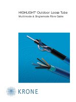
Direct Buried cable
TECHNICAL SPECIFICATIONS
We would like to comment the technical aspects as follows:
Our proposed offer fully complies with ITU-T G.652, IEC, EIA standards and has the
following characteristics:
CABLE DESIGN
- 2 96 fibres.
- Operating wavelength at 1310nm and 1550nm.
- Non-metallic central member.
- Loose buffer tubes (dual layer design) SZ stranded.
- Interstices and buffer fully filled.
- Dielectric strength member.
- Inner PE sheath.
- Corrugated steel tape for superior rodent protection.
- Outer PE jacket.
- Suitable either as
Direct Buried
and Ducted application (
DB
)
OPTICAL AND MECHANICAL CHARACTERISTICS OF A SINGLE MODE FIBRE
Refractive index profile: step
Design: matched cladding
Coating diameter: 245
µ
m
±
5
µ
m
Cladding diameter: 125
µ
m
±
1
µ
m
Mode field diameter (1310nm): 9.2
µ
m
±
0.4
µ
m
Mode field diameter (1550nm): 10.5
µ
m
±
1
µ
m
Mode field concentricity error:
≤
0.5
µ
m
Cladding non circularity:
≤
1%
Effective group index of refraction N
eff
(1310nm): 1.4675
Effective group index of refraction N
eff
(1550nm): 1.4681
Numerical aperture: 0.13
Cut off wavelength of cabled fibre:
≤
1250 nm
Attenuation at 1310nm (nominal): 0.34 dB/km
Attenuation at 1550nm (nominal): 0.19 dB/km
Dispersion in the 1285 to 1330nm window:
≤
3.5 ps/nm x km
Dispersion at 1550nm:
≤
18 ps/nm x km
Zero dispersion wavelength 1301.5
≤
λ
o
≤
1321.5 nm
Zero dispersion slope
≤
0.092 ps/(nm
2
.Km)
Polarization Mode Dispersion (PMD)
≤
0.2 ps/sqrt(Km)
Fibre Curling length
≥
4 m
Page 2 of 6
CORE MATERIAL
The core of the fibre optic, with a higher refractive index compared to the cladding, is made of SiO
2
(Silicon dioxide) doped with GeO
2
(Germanium dioxide).
CLADDING MATERIAL
The cladding of the fibre optic is made of SiO
2
(Silicon dioxide).
TYPE OF PRIMARY COATING
The primary coating is made of an UV-curable acrylate. It is applied in two layers, each of a different
Young’s modulus. The inner layer is somewhat softer than the outer one.
This coating protects the fibre against microbending losses and against abrasion.
Fibre color coding:
Fibre 1 blue Fibre 7 red
Fibre 2 orange Fibre 8 black
Fibre 3 green Fibre 9 yellow
Fibre 4 brown Fibre 10 violet
Fibre 5 grey Fibre 11 pink
Fibre 6 white Fibre 12 aqua
DIMENSION OF PRIMARY COATING
The dimension of the primary coating is 250
µ
m
±
15
µ
m.
MECHANICAL CHARACTERISTICS OF THE PRIMARY COATING
The primary coating is easily strippable by means of a mechanical stripping tool. No chemicals are
required.
MECHANICAL CHARACTERISTICS OF THE FIBRE
Proof test stress: 8 N for 1 second; strain: 1%
Breaking strength of the fibre:
≥
150 N/mm
2
Page 3 of 6
BUFFER TUBE TECHNIQUE
In the loose buffer tube technique the primary coated fibre is accommodated in a secondary coating,
called buffer tube.
The buffer tube may contain one or more fibres; the fibres are loosely laying in the tube, statistically
in the center of the tube.
Due to stranding of the buffers an overlength is produced.
(The overlength depends on stranding radius, tube diameter and lay length).
That means if a tensile force is applied to the cable, an elongation in a wide range will not result in
fibre strain and no attenuation increase is observed.
The loose buffer technique is also coping best to temperature induced contractions or dilatations of
the cable. The structure is as well a good protection against transverse compression.
As a result the whole cable construction is, within a wide range, insensitive to external influences.
REVERSE LAY (SZ) STRANDING
The elements (loose buffer tubes and if necessary filling elements) are stranded around a central
member according to the reverse lay method, which means, that the direction of stranding reverses
after a predetermined number of revolutions .
At the reverse point the elements are laying parallel to the axis of the cable.
A binder is wound around the elements in order to retain them in the proper position.
Page 4 of 6
MANUFACTURING OF A DIRECT BURIED FIBRE OPTIC CABLE
Around a FRP (Fibre Reinforced Plastic) central member, buffer tubes and if necessary filling
elements are stranded to form the core of the cable.
The central member serving mainly as anti-buckling element will be overcoated with a PE jacket if
required, to obtain the correct stranding radius.
The buffer tubes contain up to 12 fibres and are filled with a paraffine oil based filling compound.
Color coding
buffer tube 1 blue buffer tube 5 grey
buffer tube 2 orange buffer tube 6 white
buffer tube 3 green buffer tube 7 red
buffer tube 4 brown buffer tube 8 black
As well the interstices of the core are filled with a filling compound in order to block any possible
water ingress.
Aramid yarns are then stranded around the optical module to provide the required tensile strength.
An inner PE sheath (nominal thickness 1mm) is extruded above the core covering.
A corrugated steel tape is longitudinally applied over the inner PE sheath with an overlap. The
corrugated steel tape has a nominal thickness of 0.155 mm and 0.4mm above the corrugation; both
surfaces are coated with a copolymer, each one 0.05mm thick. The corrugated steel tape acts as a
rodent protection.
Finally an outer PE-jacket (approximate thickness 1.5 mm is extruded).
Please refer to the cross sectional drawing which we enclose.
MARKING
The marking of durable quality, is printed on the cable at regular interval of one meter length. The
type of legend marking on the cable is as follows:
Manufacturer’s Name. Part Number . Cable type Number of Fibres. Date of manufacturing. Metering mark
Page 5 of 6
DELIVERY LENGTH
Nominal standard length of buried cable in each drum is 1Km
±
10% or multiple (2,3,4,5,6) unless
clearly specified at time of ordering.
The wooden drum is non-returnable and will be marked with arrows to indicate the direction of
rotation.
Each drum will have a reel label with the following information:
Drum No
Batch No
Type of cable
Cable code
No of fibres
Cable length
Inner end marking
Outer end marking
Gross Weight
Year /Month of manufacture
TECHNICAL CHARACTERISTICS:
Cable type: A-DF(ZN)2Y(SR)2Y
Fibre count
2 - 30 32 - 48 50 - 96
Diameter approx.
[
mm
]
14.3 16.5 18.0
Weight approx.
[
kg/km
]
195 276 304
Min. bending radius
- during installation
- installed
[
mm
]
[
mm
]
315
285
365
330
400
360
Tensile strength
- short term (during installation)
- long term (installed)
[
N
]
[
N
]
2700
1300
2700
1300
2700
1300
Compressive stress/crush
(Attenuation increase fully reversible)
[
N/10cm
]
4000 4000 4000
Impact resistance (E=3Nm, r= 300mm)
(Attenuation increase fully reversible)
[
impacts
]
30 30 30
Operating temperature range
[
o
C
]
-30 70 -30 70 -30 70
Installation temperature range
[
o
C
]
-5 50 -5 50 -5 50
Page 6 of 6
Outer PE jacket
nom. thickness 1.5mm
Dielectric strength member
Interstices fully filled
Corrugated steel tape
Inner PE sheath
nom. thickness 1.0mm
Dielectric central member
Outer diameter approx.: 14.3 mm Weight approx.: 195kg/km
DIRECT BURIED CABLE
Buffer tube,filled
with 6 single-mode fibres.