Tài liệu GuideBook - Digital Building Telecom Access Guideline 2002 ppt
Bạn đang xem bản rút gọn của tài liệu. Xem và tải ngay bản đầy đủ của tài liệu tại đây (881.65 KB, 56 trang )
Digital River – Digital Building Telecommunications Access Guideline 2002.
August 2002 iii
Table of Contents
Introduction: The Digital Building Telecommunications Access Guideline v
Foreword v
Scope and Purpose vi
Digital River vi
The Process vii
More information and comments vii
Principle 1: Spatial Access and Design 1
1.1 Introduction 2
1.2 Communications Network Architectures 2
1.3 Telecommunications Service Entrance 4
1.4 Equipment Room 5
1.5 Backbone Pathways or Riser Shafts 7
1.6 Telecommunications closets (TC) 8
1.7 Horizontal pathways 9
1.8 Radio (Wireless) Facilities Provision 11
1.9 Standards & References 12
Principle 2: Diversity 13
2.1 Building Entry Point (BEP) 13
2.2 Equipment Room 13
2.3 Riser Shafts 14
2.4 Radio (Wireless) services 14
Principle 3: Building Services 15
3.1 Air-conditioning (HVAC) 15
3.2 Primary Power supply 16
3.3 Fire protection 18
3.4 Electro-Magnetic Radiation 18
3.5 Electro-Magnetic Interference 19
3.6 Lighting 19
Digital River – Digital Building Telecommunications Access Guideline 2002.
August 2002 iv
3.7 Access Security and Building Management 20
3.8 Standards and References 22
Principle 4: Terms of Access 23
4.1 Regulatory Provisions 23
4.2 What about carrier service providers 23
4.3 Terms of Access 24
4.4 Provision of External Communications Services 25
4.5 Standards and References 25
Principle 5: Access Management Issues 26
5.1 Timing and notification 26
5.2 ACIF Guideline 26
5.3 Conduct between Building Management & Carriers/carriage service providers 27
5.4 Tenant Consultation 27
5.5 Security and Access Systems 27
5.6 Co-location and Co-operation 27
5.7 Standards and references 28
Appendices
Appendix A - Regulatory Provisions Relating to Telecommunications Land Access 29
Appendix B – Typical spatial requirements of telecommunications facilities 34
Appendix C – Glossary of Terms 35
Appendix D – Building Access Terms 38
Appendix E – Checklist 46
Digital River – Digital Building Telecommunications Access Guideline 2002.
August 2002 v
Introduction: The Digital Building Access Guideline
Foreword
The objective and purpose of this document is to provide
information and guidance to building owners/managers
to assist them in facilitating and managing the
arrangements for access to buildings for multiple
telecommunications carriers, carriage service providers
and other service providers that are involved in the
provision of telecommunications services to tenants
located in a given building. This document also provides
information that is relevant to tenants.
The focus of this guideline is on:
• Multi-tenant buildings
• Commercial and residential buildings
• Buildings located in the City of Melbourne
• Facilitation of building access carriers and
carriage service providers to provide
telecommunications services to tenants in that
particular building
• Facilitation of provision of broadband services in a
given building by multiple carriers and carriage
service providers
• Providing information to tenants in regard to the
way in which multiple carriers and carriage service
providers can provide broadband services in a
given building
• Encouragement of an environment in the City of
Melbourne where there is multiple suppliers,
extensive competition and high take-up of
broadband telecommunications services to
buildings
In this environment of deregulation of the
telecommunications industry, there has been growth in
the number of carriers and carriage service providers
and in the development of telecommunications services
and broadband services. This has lead to a number of
issues that have emerged for building owners/managers,
carriers, carriage service providers and tenants in the
area of building access.
Key issues include:
• Building access is being sought by multiple
carriers and service providers to service tenants
• There is limited availability of space and
limitations in building services sought for
telecommunications facilities in many buildings
• End-to-end connectivity with customers is sought
by carriers and carriage service providers
• Multiple technology and infrastructure types
require accommodation and building services for
telecommunications systems and other
communications systems
• There is inadequate documentation and co-
ordination of telecommunications and other
communications infrastructure in some buildings
• The complexity of the telecommunications
regulatory environment in regard to rights and
responsibilities of carriers, carriage service
providers, buildings owners/managers and
tenants in regard to building access.
Glossary
A
CA Australian Communications Authority
A
CI
F
Australian Communications Industry Forum
A
ustralian Standard
s
refers to documents
produced by Standards Australia.
Carrier the holder of a telecommunications
carrier license granted under the
Telecommunications Act 1997. There are around
80 licensed carriers in Australia.
high bandwidth or broadband a general term
used to describe transmission at bandwidths
higher than four Mbits/sec (e.g.: high-speed data
and video services). It should be noted that some
lower bandwidth services, and called broadband,
such as ADSL operate at speeds less than 2
Mbit/s
Digital River – Digital Building Telecommunications Access Guideline 2002.
August 2002 vi
Digital River
Scope and Purpose
The purpose of this document is to provide information
and general guidance to building owners/managers. It is
recommended that building/owners managers refer to
the relevant reference material, legislation, industry
codes and guidelines, industry bodies and seek
specialist advice if they judge that it is required in areas
of building services, telecommunications services,
telecommunications regulatory aspects and other
relevant disciplines in the application of this guideline to
a specific building.
It is also highlighted that information provided in
reference sources is subject to change and
telecommunications regulatory arrangements are
subject to change and that building owners/managers
should not rely on the currency of information provided
in this guideline.
The information and scope of this guideline is grouped
into the following areas in the document:
• Spatial Access and Design (Principle 1 )
• Diversity (Principle 2 )
• Building Services (Principle 3 )
• Terms of Access (Principle 4 )
• Access Management Issues (Principle 5)
• Telecommunications Regulatory Principles
• Proposed Building Access Terms (Appendix D)
This guideline recognises that specific legislative rights
and obligations exist for telecommunications carriers
and seeks to integrate these into the approach
suggested for building owners/managers in facilitating
provision of telecommunications services to tenants.
The guideline also recognises that the industry body
ACIF (Australian Communications Industry Forum) is
planning to issue an ACIF Guideline Building Access
Operations and Installation (DR G571) covering the area
of procedures and processes for building access. City of
Melbourne supports the ACIF initiative and supports
building owners/managers, carriers and carriage service
providers adopting the procedures and processes
proposed by ACIF. This guideline is intended to co-exist
with the proposed ACIF Guideline and to complement
the ACIF Guideline by providing a document with focus
on information and guidance for building
owners/managers in the area of building spaces and
services that are required to facilitate multiple
carrier/service provider access to a given building.
Although the focus of this guideline is facilitation of
telecommunications services the document recognises
that building owners/managers are operating in an
environment where in many cases the building spaces
and building services sought by carriers and carriage
service providers are also required by other
communications systems. These other communications
systems include building management systems and
communications systems operated by tenants or other
suppliers on behalf of tenants. However, this guideline is
not intended to provide information and advice to
building owners/mangers or tenants in regard to spatial
or building service requirements of these other
communications systems.
The guideline also recognises that providers of radio
(wireless) based systems and services may seek access
to a building for the purposes of serving tenants within
that building, for serving customers located outside that
building or a combination of the both.
This guideline addresses the requirements of radio
based systems provided to service building tenants,
however, the scope of this guideline does not include the
provision of information and guidance in regard to
building spaces and building services that may be
sought by providers of radio based systems that are
designed primarily to service customers that are not
located in the building where access is sought.
Digital River was commenced in July 2000 by the
Committee for Melbourne, City of Melbourne, Docklands
Authority and the Property Council of Australia (Vic).
During the subsequent 12 months, the Building
Commission joined the founders and, at a later date both
Digital Harbour and Versitec Consulting also joined the
Digital River roundtable. Digital River was directed at
identifying initiatives to address current market barriers
to, and create widespread public awareness and
acceptance of, broadband. Digital River recognised that
Melbourne’s and ultimately Victoria’s economic future
will be enhanced by making Melbourne and Victoria a
more attractive investment target for locating and
developing Business.
The Digital Building Telecommunications Access
Guideline is one of Digital River’s initiatives and the City
of Melbourne has been proud to lead this project.
Multimedia Victoria has provided significant funding
Digital River – Digital Building Telecommunications Access Guideline 2002.
August 2002 vii
The Process
More information and comments
Consultants and Advisors
support to the City of Melbourne for the launch and
implementation of the guideline project recognising that
the project has several aspects that are consistent with
the State Government of Victoria’s multimedia policies
and initiatives.
During the last five years the telecommunications
industry in Australia has undergone extensive change.
At the time of writing this guideline, approximately 80
licensed carriers existed in Australia, with many seeking
to provide telecommunications services to commercial
and residential tenants in buildings.
The Digital Building Telecommunications Access
Guideline was developed in consultation with the market
including carriers, building owners, agents and
telecommunication advisers to identify existing issues
and potential solutions.
Market information was then coupled with research into
best practice and a review of Australian Standards and
legislation.
This document is not intended to be a legally
enforceable document, however it resides within a
regulated environment. The principles and guidelines
outlined in the DBTAG are made in consideration of
market feedback and are intended for use as
complementary documents to the relevant regulations
and legislation.
To make comment on this guideline or to seek further
information please contact:
The City of Melbourne and Digital River would like to
acknowledge and thank the following consultants and
advisors for their assistance in the preparation of this
document.
• Internet Architecture Pty Ltd: for preliminary
document preparation
• Gibson Quai Pty Ltd: for reviewing the document
and providing additional technical and engineering
content and advice
• Matthew Nicholls - Technology and
Communications Law: for reviewing the document
and providing legal content and advice
Digital River and City of Melbourne Disclaimer
The information in this document is current as at the time o
f
first publication and may or may not be updated thereafter.
Persons using this document should ensure that they check
the currency of the information in this document and update
that information as and where necessary.
This document is not intended to impose legal rights or
obligations on any person, nor is anything in this document
intended to create a contract or relationship of any kind as
between any persons.
Nothing in this document constitutes (or is intended to
constitute) legal, engineering, design or other professional
advice. This document is intended as a guide only.
A
ccordingly, persons using this document should not rely on
the information in this document, but should first see
k
independent professional advice specific to thei
r
requirements.
To the maximum extent permitted by law, Digital River and
the City of Melbourne (including the authors of this documen
t
and all persons involved in the preparation of this document)
hereby expressly disclaim and exclude all liability to any
person for any loss, damage, injury or other consequence
(direct or indirect), howsoever caused (including without
limitation by way of negligence) which may arise from or in
any way relate to any person’s use of, reliance on or non-
reliance on, this document.
The reference to any good, service, supplier, person o
r
company in this document is for illustration purposes
only. As to such goods, services and persons, Digital
River and the City of Melbourne make no
representations as to: any affiliation with them; thei
r
quality, accuracy, veracity or otherwise; or any approval,
endorsement or disa
pp
roval of them.
Digital River – Digital Building Telecommunications Access Guideline 2002.
August 2002 1
Principle 1: Spatial Access and Design
“Building space should be able to accommodate multiple independent telecommunications facilities ”
Objective: To encourage a competitive market within
city buildings for telecommunications carriers and
service providers that will result in availability of high
capacity telecommunications services from multiple
carriers. The provision of suitable minimum
accommodation and building services will give more
carriers and carriage service providers the opportunity to
provide services to a building, ensuring that service
access is not limited to services from one carrier to a
given building.
Current key issues include:
• Limited availability of space for
telecommunications facilities in buildings
• Multiple-carrier building access being sought by
carriers and service providers to service tenants
• End-to-end connectivity with customers
• Multiple technology and infrastructure types
requiring accommodation and building services for
telecommunications systems and other
communications systems
• Inadequate management and identification of
telecommunications and other communications
infrastructure in some buildings
A number of facilities are required in a building to ensure
that telecommunications services, other communications
services and broadcasting services can be adequately
provided for.
This guideline suggests that except where permitted by
Standards and Codes, the building accommodation and
building services that are the subject of this document
should be used exclusively for telecommunications,
other communications and cable broadcasting services
and include:
• Telecommunications service entrance facilities,
lead-in ducts and building entry points
• Entrance rooms or space
• Equipment rooms
• Backbone pathways or riser shafts.
• Building distributor or MDF
• Floor distributor
• Horizontal pathways
• Telecommunications outlets
• Lead-in cabling
Glossary
A
ccess—giving access to a building includes access
to all areas required for installation and maintenance o
f
telecommunications facilities. This may include
Equipment Rooms, Entrance Rooms, riser shafts and
horizontal pathways as defined.
A
ccess hole—an underground chamber constructed
on the street side cable route to give access to jointing
or feeding of new services and for maintenance.
Building Entry Point. (BEP) — a point at which a line
that is used to provide a carriage service to an end-
user in a building meets the outer surface of tha
t
building, immediately before entering the building.
AS/ACIF S009: 2001 4.2.2
Building management—for this document means an
y
person or body that controls the building. Includes
building owner, building manager, leasing agent, bod
y
corporate, etc.
Campus—refers to a local network arrangement,
servicing a number of buildings, rather than just a
single building. Examples of these include universities
and many hospitals.
Carriage service provider (CARRIAGE SERVICE
PROVIDERS)—is a supplier of carriage services using
network units owned by carriers.
Entrance Room —this room is often the first room in
the building in which the conduits from the access-hole
appear. This room or space may contain networ
k
interface devices and telecommunications equipment. .
Equipment Room—a centralised room fo
r
telecommunications facilities. It may house equipmen
t
such as switches, computing equipment, video
switches for serving the tenants
Digital River – Digital Building Telecommunications Access Guideline 2002.
August 2002 2
1.2 Communications Network
Architectures
1.1 Introduction
• Building backbone cable
• Horizontal cable
• Telecommunications closets
• Telecommunications equipment/facilities
This document is intended as a guideline to building
owners and managers. The actual size, specifications
and structural design of all accommodation and building
services provided for telecommunications facilities and
other communications facilities should be referred to
professional telecommunications advisers, building
design specialists, carriers and tenants as appropriate
and should adhere to relevant Australian Standards and
Building Codes.
The building’s accommodation of entrance room,
equipment rooms and communications pathways should
aim to be able to accommodate several different types of
network architectures.
Multiple Network Architectures
The communication network architectures in a multiple
storey building include those for telecommunications
carriers and service providers, building management
and control systems, tenant computer and
communications systems and other related systems.
The technology architectures in use for delivery of
telecommunications carrier and carriage service
providers services within buildings include:
• Telephone cabling in vertical and horizontal
pathways
• Special purpose copper cabling in vertical and
horizontal pathways for delivery of high bandwidth
services
• Optical fibre cabling in vertical and horizontal
pathways for delivery of wide bandwidth services
• Coaxial cable in vertical and horizontal pathways
for delivery of Pay TV, high-speed Internet and
telephony services
• Specialised antenna cables in vertical pathways
for provision of mobile telephone and other radio-
based services
• Electronic equipment located in entrance room(s),
equipment room(s), telecommunications closets
and tenancy areas
• Copper and optic fibre cables entering the building
• External antenna systems for connection of
carriage services to the building. External antenna
systems may also be associated with provision of
Carriage Services to customers not located within
the building
Other communications architectures are also in use
within buildings including:
• Multipair data cabling in vertical and horizontal
pathways for LAN systems, other computing
systems, security systems, control systems, video
systems etc.
Glossary
Horizontal pathways— are horizontal cable paths.
These refer generally to pathways for distribution
cabling from telecommunications closet(s) and/or rise
r
shaft(s) to cable outlets. These include ceiling space
systems, under floor systems and skirting duc
t
systems.
MOCS— Melbourne One Call Service (Dial before you
Dig).
Riser shaft—is a vertical pathway for backbone
distribution cables within a building. It is a
physical vertical pathway between floors of a
building. Riser shaft types through floors include
rectangular slots and circular holes. The rise
r
shafts are typically filled with fireproof material to
prevent them from becoming between floo
r
pathways for fire.
Telecommunications— the carriage of
communications by means of guided and/or unguided
electromagnetic energy
Telecommunications Service Entrance—the point a
t
which telecommunications pathways enter or leave a
building.
Telecommunications Closet [TC]—this houses
equipment and cable terminations for horizontal wiring
for each floor. Other names include communication
s
closet, floor distribution
p
oint, wirin
g
closet.
Digital River – Digital Building Telecommunications Access Guideline 2002.
August 2002 3
• Coaxial and fibre-optic cables in vertical and
horizontal pathways for LAN systems, other
computing systems, security systems, control
systems, video systems etc.
In addition, some buildings also have communications
systems that are not specifically related to servicing the
building’s occupants. These include:
• Mobile telephone, mobile data, link radio and
mobile radio systems which have cabling in
vertical pathways for connection of these systems
to a carriers’ network
• Television and radio broadcasting systems which
have cabling in vertical pathways for connection of
these systems to a carriers’ network
• Other systems such as weather monitors,
environmental monitoring, video surveillance,
which have cabling in vertical pathways for
connection of these systems to a carriers’ network
In-building Common Use Telecommunications
Infrastructure.
Building owners typically provide a range of
accommodation and building services in buildings to
facilitate the provision of telecommunications services to
tenants, to accommodate tenant communications
systems and to accommodate other communications
systems. This accommodation and services typically
includes building entry points, entrance room(s),
equipment room(s), vertical pathways, horizontal
pathways, primary power, telephone backbone cabling
(in some cases) back-up power (in some cases),
lighting, HVAC and other building services. These
facilities are typically provided on a common use basis
with carriers, carriage service providers, tenants,
building owner/manager and other suppliers sharing
these infrastructure facilities. In cases where the carriers
or carriage service providers proposed installations
result in additional expenditure, carriers, carriage service
providers and other service providers may fund specific
works and/or upgrades of the facilities (such as
additional electrical distribution circuits and circuit
breakers, additional air-conditioning, additional cabling,
back-up power systems, access control systems etc.) to
meet the requirements of their specific systems.
Carriers, carriage service providers, other service
providers and tenants in many cases establish
agreements in relation to use of common-use
infrastructure.
In the specific case of vertical backbone cabling, building
owners typically provide backbone telephone cabling in
vertical pathways in multi-storey buildings and in some
cases inter-building telephone cabling in a multi-building
environment.
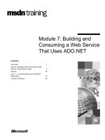
Entrance Room (Often
combined with
Equipment Room)
Workstation
Telephone
Fax
BEP or Lead-
in to building
Riser Shaft(s)
Horizontal
pathways as
Cable Trays
or under floor
area.
Telecommunications
outlets
Telecommunications
closets (TC)
Floor Distributor (FD)
Equipment Room (ER).
(Often contains
Building Distributor)
Entrance pathways
Vertical Riser
Shaft
ER
TC
123
456
789
*8#
123
456
789
*8#
to BEPto BEP
123
456
789
*8#
123
456
789
*8#
BD
FD
Digital River – Digital Building Telecommunications Access Guideline 2002.
August 2002 4
1.3 Telecommunications Service Entrance
This is done to facilitate tenants being connected to
telecommunications carrier services without the need for
disruptive and time-consuming provision of new
telephone cables for each building tenant.
Typically, these backbone cables are provided and
owned by the building owner and made available for use
by tenants and carriers.
In some cases, building owners may also provide optical
fibre cables in vertical pathways and between buildings.
However, due to the diverse range of architectures used
by telecommunications carriers, in most cases in a multi-
storey building, carriers will still need to install additional
equipment and cabling to deliver the full range of
telecommunications services to tenants.
These carrier systems of additional equipment and
cabling require access and accommodation, including
telecommunications service entrance, entrance room(s),
equipment rooms, telecommunications closets, vertical
and horizontal pathways.
In accordance with the telecommunications regulatory
requirements or as part of a commercial arrangement,
telecommunications carrier infrastructure provided in
buildings may be used by other carriers and carriage
service providers.
Equipment and Cabling requirements
This document does not contain specific advice on the
type of communications equipment and cabling that
should be installed into a building as this is the
responsibility of carriers, carriage service providers,
other service providers and tenants other than in the
case of the building owner/manager providing common
use infrastructure. Issues relating to choosing the most
suitable communications equipment and cabling,
especially in the case where a common-use
infrastructure is provided, should be referred to a
telecommunications advisor and building services
advisor (where appropriate) and planned in consultation
with carriers where appropriate.
To provide telecommunications services and cable-
based broadcasting services to a building, lead-in ducts
need to be laid below pavement level from an access
hole outside the property boundary that contains cables
from an underground street system, to the building’s
entry point.
In accordance with appropriate Australian Standards
and best practice, building management should meet
spatial and structural requirements for all relevant
building entrance facilities and contact relevant local
authorities and MOCS (Dial before you Dig) for
information on existing conditions.
Any location where a lead-in duct enters the building is
defined in this document as the Building Entry Point
(BEP). In some cases for diversity two or more building
entry points are provided to a building. It is also noted
that in some cases a carrier may use a radio-based
system with antennas mounted on the building to
provide the primary or secondary building entry point to
a building.
Entrance Pathways and Entrance Rooms
In the current environment of multiple carriers and
changing technology architectures (eg extensive use of
fibre optic cable) the identification of the appropriate
sizing of entrance pathways and entrance rooms is not
straightforward. In many cases building
owners/managers are operating in a situation where the
disruption and costs of providing additional facilities are
significant.
A
n exam
p
le of an ER
Digital River – Digital Building Telecommunications Access Guideline 2002.
August 2002 5
1.4 Equipment Room
Building management should obtain advice from
telecommunication advisers and tenants and liaise with
carriers to agree on a suitable location, type, size and
number of entrance pathways to meet their cabling
requirements.
The following issues should be considered in the
consideration of entrance pathways and entrance
rooms:
• Carriers have certain obligations in relation to co-
locating facilities and co-operating with others.
See section 5.6 of this Guideline for further details
• Multiple entrance pathways may be sought by
carriers and tenants to provide diversity of
connections to a given building. In these cases
multiple entrance rooms and equipment rooms
are highly desirable to maximise the degree of
diversity that is provided
• The entrance room is required to accommodate
the building distributor (building MDF) cable
frames, which is typically either wall, mounted or
located in freestanding frames/racks
• In many cases the entrance room and equipment
room are collocated
• Information on the spatial design of underground
lead-in ducts and entrance facilities is given in AS
3084-1993 s.7.3 and s.7.4 and AS/ACIF
S009:2001 s.5.5
• Additional information is provided in Appendix B,
”Typical Spatial Requirements for
Telecommunications Facilities”
It is noted that in the case of large-scale multi-unit
apartment complexes or campus-style commercial
arrangements, where underground networks may be
required to link up all the buildings within the
development, provision may also need to be made for a
campus distributor and an alternate inter-building
backbone pathway. Alternatively, separate lead-in ducts
along the perimeter of the estate for connecting an
individual building may be provided.
In the current environment of multiple carriers and
changing technology architectures (eg many carriers
seeking accommodation, extensive use of optic fibre
cable systems and reduction in physical dimensions of
The size of the ER will depend on the tenable
area of the building
Positioning of an ER under water pipes should be
avoided
Digital River – Digital Building Telecommunications Access Guideline 2002.
August 2002 6
equipment) the identification of the appropriate sizing of
equipment rooms is not straightforward. In many cases
building owners/managers are operating in a situation
where the disruption and costs of providing additional
facilities are significant. For a building to facilitate
provision of multiple carrier systems and services,
management will need to provide one or more dedicated
equipment rooms with enough suitable space to house
carrier communications equipment and in some cases
equipment associated with tenants and/or associated
suppliers. Provision for the equipment accommodation
for a minimum of four carriers is suggested.
The room should house only telecommunications
equipment or related compatible equipment.
It is desirable that access to the equipment room be
available on a 24 hour, 7 days a week basis.
Refer to Appendix B for suggested dimensions of
equipment rooms to accommodate a minimum of four
carriers.
General considerations in regard to equipment room
requirements are as follows:
• Carriers have certain obligations in relation to
collocating facilities and co-operating with others.
See section 5.6 of this Guideline for further details
• Multiple equipment rooms may be sought by
carriers and tenants to facilitate increased
diversity of connections to a given building
• In many cases the entrance room and equipment
room are collocated. In these cases the room will
be required to accommodate the building
distributor (building MDF) cable frames, which is
typically, either wall mounted or located in
freestanding frames/racks
• The room should be located above the building’s
lowest basement level and be resistant to flood
damage
• The room should be easily accessible to the
carriers
• The room should have pathways to the vertical
pathway(s), campus pathways and the entrance
room (if separate) as well as the lead-in ducts if
no entrance room is provided
• No water pipes, sewage pipes, water drainage,
water sprinklers, high voltage power supply cables
or power transformers shall be installed within the
equipment room
• The equipment room should be protected against
water infiltration and if there is a risk, then a floor
drain must be provided
• No air ducts, except for ducts that provide service
to the equipment room, should be installed or
routed through the equipment room
• There should be no openings in the room except
for the door, the ventilation ducts and cabling
ducts. All windows, if any, must be shut and
sealed. If necessary, window coverings and
security grilles should be provided. Penetrations,
openings and doors must adhere to suitable fire
resistance levels where applicable. (Also see
Principle 3.3 Fire protection)
• The room should not be located where it is
exposed to vibration due to vehicles or machinery
• There must be sufficient lighting provided in the
room. in accordance with AS 3084-1993 s. 6.2.3.8
• A dedicated electrical power supply should be
provided to the room. The power supply should be
connected to an essential supply generator if
provided
• The temperature and humidity range for the room
should be between 180C and 240C with 30% to
55% humidity as per AS 3084-1993 s.6.2.3.6.2
• The floor, walls and ceiling should be painted in
light colours to assist in the room illumination and
to minimise dust generation
A suitable layout of an equipment room should
most importantly take into account the following:
• The potential quantity and volume of equipment to
be used by multiple carriers
• The expected frequency of accessing equipment
racks for maintenance purposes
• Security and access arrangement for access
to/from the equipment room to external parking for
the transport of equipment
• Ensure that room for future expansion is allowed
wherever possible
For further information refer to AS3084 – 1993 s.6
Digital River – Digital Building Telecommunications Access Guideline 2002.
August 2002 7
1.5 Backbone Pathways or Riser Shafts
In the current environment of multiple carriers and
changing technology architectures (e.g. many
carriers seeking accommodation, extensive use of
optic fibre cable systems and reduction in physical
dimensions of equipment) the identification of the
appropriate sizing of riser shafts is not
straightforward. In many cases building
owners/managers are operating in a situation
where the disruption and costs of providing
additional facilities are significant.
Riser shafts provide a vertical passage for
telecommunications services to be distributed to each
floor. Therefore, it is important that carriers are provided
adequate cabling space and access in riser shafts so
they can provide an effective service within the building.
Riser shafts are also used for cabling associated with
other communications services including:
• Backbone cabling for tenant telephone systems
• Pay TV cabling
• Antenna cables (e.g. mobile telephone systems)
• Tenant LAN/WAN systems
• Security and surveillance systems
Riser shaft penetrations between floors are often
accessible at each floor of a multiple storey building at a
riser shaft cupboard that also accommodates a
telecommunications closet.
In accordance with appropriate Australian Standards
and best practice, building management should provide
adequate spatial, structural and access requirements for
dedicated telecommunication riser shafts or backbone
pathways. If the network architecture is not known,
spatial provision for a minimum of four carriers is
recommended. Refer to Appendix B for suggested
minimum riser shaft (between floor penetration)
dimensions to accommodate a minium of four carriers.
For further information refer to AS 3084-1993, 3.2.2.To
obtain maximum utility from the riser shafts, they should
ideally be placed through a common part of the building
and central to the distribution area in which they are to
serve.
To ensure the proper fixing of cables, the
accommodation associated with riser shafts should be
fitted with appropriate cable fixing devices. (eg: steel
cable racks, perforated cable trays, etc.) These devices
will be fixed along the entire length of the vertical
pathway from the entrance or equipment room to the top
of the building and should only be installed on the
permanent structure of the building to avoid difficulties
with future rearrangements of partition walls. Vertical
pathway fixings used will depend on the type and
quantity of cables to be installed. All cabling fixed in the
building should conform to current cabling standards.
To provide flexibility of cable runs and to improve
reliability of telecommunication services, provision of
more than one riser shaft is highly desirable in buildings
with large floor areas.
For firestopping through riser shafts etc. refer to
AS 3084-1993 s.3.2.2.3
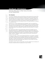
Provision for access to cabling must be
provided within the riser shaft
750mm
1500mm
2000mm
150mm clearance all-
round for vertical cabling
Steel
decking
Vertical
Cabling
Floor Distributor
Typical vertical riser shaft design
Digital River – Digital Building Telecommunications Access Guideline 2002.
August 2002 8
1.6 Telecommunications Closets (TC)
Access to riser shafts
Access to each riser shaft will be necessary on each
floor and should always be from a corridor or common
area to avoid disturbance to tenants. Access is best
provided by a hinged-door of standard height to give
reasonable access to the cables.
In the current environment of multiple carriers and
changing technology architectures (eg many carriers
seeking accommodation, extensive use of optic fibre
cable systems and reduction in physical dimensions of
equipment) the identification of the appropriate sizing of
telecommunications closets is not straightforward. In
many cases building owners/managers are operating in
a situation where the disruption and costs of providing
additional facilities are significant
The telecommunications closet (TC) contains
telecommunications equipment, cable terminations for
the horizontal wiring and the cross-connection wiring to
the backbone cabling. In some cases the TC is also
used to accommodate equipment associated with tenant
systems and other systems. As a general guideline, the
size and spacing of telecommunications closets should
be in accordance with AS 3084-1993 s.5.2 however,
depending on the requirements to facilitate multiple
carriers and to accommodate tenant systems, additional
accommodation may be required.
Typically, in large buildings, the Telecommunications
Closet is located on the services core(s) and the riser
shaft floor penetrations are located within the same
accommodation area as the Telecommunications
Closet.
In general, the following requirements should be met:
• Ideally, at least one telecommunications closet
with adequate access should be provided on each
floor. As a general guide, as per AS3084-1993
5.2.2.1, each Telecommunications Closet should
serve a maximum floor area of 1500m2 . Should
any cable run exceed 90 metres in length then a
further Telecommunications Closet is required.
The 90-metre distance limit is particularly relevant
where the horizontal cabling system is an
integrated telephone and data system
• Adequate provision to accommodate a minimum
of four carriers is suggested
• There should be a rigid wall that is capable of
supporting the equipment
• Telecommunications closets must be located
away from water pipes and fire hydrants
Sufficient access should be provided into riser
shafts
Digital River – Digital Building Telecommunications Access Guideline 2002.
August 2002 9
1.7 Horizontal Pathways
Horizontal pathways allow the installation of
telecommunications cabling from each
telecommunications closet to the tenant area in an office
or apartment. The pathways may be in conduit, cable
tray and ducts, ceiling or perimeter, infloor or under floor
access. In some cases the use of catenaries may be
employed. Horizontal pathways are typically inherent in
the building design and hence are managed by the
building owner/manager and the tenant, however in
some cases parts of the horizontal pathways are
provided by the tenant by means such as partitioning
ducting.
In all cases, the pathway should be designed to
accommodate all types of telecommunications cable,
other distribution cables and also have spare capacity to
allow for expansion. It is noted that although the industry
practice is for use of integrated voice and data horizontal
cabling systems ( eg Category 5 cabling ) that in many
cases there are still separate telephone and data cabling
systems in many tenancy areas due to historical
installations and/or use of certain computer systems
which have specific cabling systems.
In general, building management and tenants should
provide horizontal distribution pathways with spatial
design in accordance with AS 3084-1993 Section 2.
However, it is highlighted that the requirements will be
specific to particular tenant requirements for computer
system and telephone system internal cabling in addition
to telecommunications services.
Building management should liaise with
telecommunications advisors, building services advisors,
existing and prospective tenants to ensure that the most
appropriate horizontal pathways are used for the
planned network architecture
.
Methods of distribution
To service the building tenant work areas, building
management should provide one or more of the
following horizontal distribution methods:
Infloor
There are several types of infloor ducting; some are
incorporated in the concrete when the building is being
constructed. Others, such as freestanding duct, are not
embedded in the concrete. Refer to AS3084-1993
s2.2.1.3 for the design information.
Access floor
This requires the construction of a floor, from floor
panels supported on pedestals. Design guidelines for
this type of floor are given in AS 3084-1993 s. 2.3
Pedestals
Floor Panels
Power cables
Telecommunications
cables
If ducts not used, separation between cables
is required for EMI prevention.
Typical underfloor cabling
A cable tray attached to ceiling
Digital River – Digital Building Telecommunications Access Guideline 2002.
August 2002 10
Conduit
This may be constructed from rigid metal or PVC. This
method is mainly used where the telecommunications
outlets quantities are low in density and their positions
are likely to be permanent. For design information refer
to AS 3084-1993 s. 2.4.
Ceiling Pathway
Ceiling spaces may be used for the provision of
pathways for telecommunications cables. Generally this
requires the provision of ducting or troughing, such as
cable trays. The cables must not be laid directly on the
ceiling tiles.
Should the ceiling space be inaccessible, such as
behind fixed ceiling tiles, or plaster, these spaces should
not be used for a pathway unless a duct or conduit with
draw wire is provided.
Access to the pathway is through the ceiling where the
tiles must be of the removable or lay-in type. Refer to
AS 3084-1993 s. 2.6.
Perimeter Pathways
These pathways are often located as a skirting duct. AS
3084-1993 s. 2.7 discusses in detail the types and the
general design guidelines for this type of pathway.
A highly detailed description regarding pathways may be
found by referring to Section 3 of the Communications
Cabling Handbook, Module 2, HB 29:2000.
Residential Premise
The horizontal pathway requirements of multiple
dwelling residential premises will in general need to be
specifically developed for the particular building to take
into account aesthetic requirements and specific plans
such as provision of outlets for telephone, Pay TV, free
to air TV and computer systems. Typically in the case of
residential apartments, where integrated wiring is
employed, telecommunications wiring is brought into the
apartment from the floor distributor (FD) where it is
connected to a disconnection test point (DTP). This
enables tests to be undertaken for both, in the direction
of the network and in the direction of the tenant’s
equipment. After the DTP there is a distribution device
(DD) from whence cabling in a star configuration goes to
each telecommunications outlet. In some cases,
particularly where there is existing cabling, the point
between the network and the customer may be at the
building distributor.
If the building is wired using an integrated cabling
system, a detailed description of the wiring, pathways
and installation requirements is described in AS
3086:1996.
Building management should liaise with
telecommunications advisors and building services
advisors to ensure that the most appropriate horizontal
pathways are used for the planned network architecture.
In-wall
socket
Conduit
Cable
False
Ceiling
Cable tray
Cable distribution through a false ceiling
Digital River – Digital Building Telecommunications Access Guideline 2002.
August 2002 11
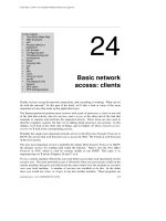
1.8 Radio (Wireless) Facilities Provision
Providers of radio (wireless) based systems and
services may seek access to a building for the purposes
of serving tenants within that building, for serving
customers located outside that building or a combination
of the both.
The purpose of this guideline is assist building
owners/managers in facilitating the access of multiple
telecommunications carriers and service providers to
provide high capacity services to building tenants.
For the cases of organisations seeking building access
for the purpose of providing services to their own
customers in general rather than solely for provision of
services to tenants of the building (eg mobile radio base
station facility, mobile telephone base station facility) a
range of issues in regard to accommodation and building
services arise, plus issues in regard to rights of access
for carriers. Building owners/managers should seek
professional advice from telecommunications advisors,
building services advisors, carriers and other advisors in
regard to these facilities. It is noted that these facilities
may have requirements for use of inbuilding common-
use infrastructure such as riser shafts, equipment rooms
and building services.
For the case of carriers seeking building access for radio
based facilities to provide services to tenants, building
owners/managers should apply the general principles of
this guideline in regard to provision spaces and building
services.
In-building requirements
The nature and design of carrier radio based systems for
provision of services to building tenants range widely
from very small external antennas and small internal
equipment to relatively large antenna systems and
requirements for equipment racks.
The arrangements need to be dealt with on a case-by-
case basis with the carrier, for access to rooftop
equipment accommodation and mounting locations for
antennas.
Carrier requirements for access to vertical riser shafts,
the telecommunications equipment room and building
services such as power should be made in a manner
that is consistent with the principles for carriers’ access
to these facilities that are outlined in other sections of
this guideline.
Building owners/managers should take into account a
number of additional items in making arrangements for
carriers to provide radio-based systems to service
building tenants including:
• Carriers should be responsible to ensure that
external equipment including antennae and cables
meet appropriate structural and wind load
requirements and to demonstrate this to building
owners
• The ACA has regulatory powers in regard to
protection of health and safety of persons
exposed to non-ionising Electro Magnetic
Radiation (EMR). The ACA does not have
regulatory powers in relation to ionising radiation
such as X-rays
• The ACA has been instrumental in a process of
development and consultation in relation to EMR
limits in the communications industry (including
the Australian Radiation Protection and Nuclear
Safety Agency (ARPANSA) and the Australian
Communications Industry Forum (ACIF)). The
ACA has requested public comment in regard to
the ACA proposal to adopt the EMR limits set by
the ARPANSA standard “Radiation Protection
Standard Maximum Exposure Levels to
Radiofrequency Fields – 3kHz to 300 GHz” which
was issued in May 2002
• It is anticipated that this process will result in
changes to the current interim standards and
responsibilities in regard to EMR for
manufacturers/importers/agents, distributors and
resellers, and operators and users of equipment
that generates EMR
• It is also noted that ACIF published in April 2002
the Industry Code ACIF C564: 2002 Deployment
of Radiocommunications Infrastructure, which is
understood to be intended to complement the
ARPANSA standard. As at July 2002 this Code is
Radio Communications on rooftop
Digital River – Digital Building Telecommunications Access Guideline 2002.
August 2002 12
1.9 Standards and references
under consideration by the ACA for registration as
an industry code
• Carriers should agree to remove the radio-based
facilities and make good in the event that the
facility is no longer in use to provide service to
building tenants
• Please refer to section 3.1 for further information
on EMR aspects of radio installations
To keep abreast of developments in industry, these
Standards and references from the ACA, Standards
Australia and ACIF are periodically amended or new
editions are published. It is therefore important that
readers refer to these organisations to ensure that they
are in possession of the current document.
The following standards, references and codes,
incorporated in the Standards Australia document,
“Communications Cabling Manual”, are relevant to this
principle:
AS3084-1993
Telecommunications Pathways and Spaces for
Commercial Buildings
ACA TS 008-1997
Requirements for Authorised Cabling Products
AS/ACIF S009:2001
Installation Requirements for Customer Cabling (Wiring
Rules)
AS HB 29:2000
Communications Cabling Handbook
AS/NZS 3080: 2000
Telecommunications Installations - Integrated
Telecommunications cabling systems for commercial
premises
The following are relevant standards /regulations/codes.
ACCC Facilities Access Code 1999
A code of access to telecommunications transmission
towers, sites of towers and underground facilities
DR ACIF: G571 : April 2001
Building Access Operations and Installation
Note that this reference is in draft form
ACIF C564:2002
Deployment of Radiocommunications Infrastructure
ARPANSA . Radiation Protection Standard – Maximum
Exposure levels to Radiofrequency fields. May 2002
AS 1170
Minimum design loads on structures
AS 1530
Methods for fire tests on building materials, components
and structures
AS/NZS 2053
Conduits and fittings for electrical installations
AS 2118
Automatic fire sprinkler systems
AS2772.2-1998
Radiofrequency radiation - Principles and methods of
measurement – 300kHz – 100 GHz
Building Act 1993
Building Regulations 1994
Building Code of Australia 1996
City of Melbourne Local Laws
Telecommunications Act 1997
Telecommunications Code of Practice 1997
Digital River – Digital Building Telecommunications Access Guideline 2002.
August 2002 13
Principle 2: Diversity
"Provision of spatially diverse telecommunications connections to a building "
2.1 Building Entry Point (BEP)
2.2 Equipment Room (ER)
Objective: This principle addresses the issue of
diversity or redundancy in the telecommunications
services to a building and the associated requirements
for diversity in building spaces and building services that
may be sought by carriers, carriage service providers
and tenants. It aims to outline requirements for a
building in order to facilitate provision of the highest
possible level of telecommunications service reliability.
Typically this is achieved through the provision of a
minimum of two building entry points so that carriers can
provide connections to the public network via two
geographically diverse routes.
This guideline is intended to provide guidance to building
owners/managers in regard to potential requirements of
tenants and carriers/carriage service providers for
building spaces and building services to facilitate the
provision of diverse telecommunications services. The
requirement for diversity in telecommunications
connection to a building will vary with the requirements
of individual tenants and the size of a building. The
requirement is however, increasingly important for
communications intensive tenants.
The provision of full diversity of a telecommunications
service to a tenant is a complex design process that is
ultimately the responsibility of carriers and carrier
customers to determine. However, the provision of
diverse telecommunications services to a given building
will typically generate requirements for building spaces
and building services which support the diverse service
provision. The potential requirements may include
diverse Building Entry Points, diverse Entrance Rooms
and/or Equipment Rooms, diverse vertical riser shafts,
diverse horizontal pathways and back-up to primary
power.
The provision of diversity in building spaces and
services to facilitate diversity in telecommunications
services to a building should be carried out in
consultation with tenants, carriers and carriage service
providers where feasible.
Building space and building service diversity issues
should also be referred to a professional
telecommunications adviser and building services
advisor.
The requirement for provision of diverse building entry
points is dependent on tenant requirements, however as
a guide it is suggested that as a minimum, one alternate
entrance be included in new buildings or in
reconditioned buildings with a lettable floor area greater
than 50,000 m
2
where possible. (Refer to Appendix B ).
Where a second BEP is provided, a second entrance
room (or equipment room where it is collocated) may be
sought to allow for spatial diversity in the building
distributor and other equipment.
It is highlighted that carriers and tenants may also seek
a radio-based facility to provide diverse connection.
The requirement for provision of diverse equipment
rooms is dependent on tenant requirements however as
guide it is suggested that a second equipment room be
considered for new buildings and in reconditioned
buildings with a floor area greater than 50,000 m
2
. A
possible approach in the case of existing buildings
where the existing single equipment room is of
insufficient size is to provide an additional equipment
Glossary
A
lternate Entrance—a supplementary service
entrance facility into a building using a differen
t
routing to provide diversity of service and assurance
of service continuity. AS3084-1993, S.1.4.4
Building Entry Point (BEP) —a point at which a
line that is used to provide a carriage service to an
end-user in a building meets the outer surface o
f
that building, immediately before entering the
building. AS/ACIF S009: 2001 4.2.2
.
Spatial or geographical diversity — the use of two
independent facilities that do not have elements
located on the same route or same accommodation.
This minimises the risk of all services being los
t
through damage.
Digital River – Digital Building Telecommunications Access Guideline 2002.
August 2002 14
2.3 Riser Shafts
2.4 Radio (Wireless) services
room to provide diversity and additional floor space. It is
noted that an alternative to diverse equipment rooms is
the use of tenant floor areas and/or telecommunications
closets to accommodate equipment.
In the case of residential buildings, provision for a
second ER is not considered to be a key requirement for
tenants. It is noted that individual tenant requirements
for diversity may be provided by carriers by the use of
fixed and mobile radio services.
It is critical to consider a disaster recovery strategy as
part of the overall diversity of the building infrastructure.
For a high level of diversity when two ERs exist, one
should be able to continue operating if the other is taken
out of service. This means that diversity of building
services such as primary power and Heating Ventilating
Air Conditioning (HVAC) for the diverse Equipment
Rooms will need to be considered.
The requirement for provision of diverse riser shafts is
dependent on tenant requirements however as guide it
is suggested that a second riser shaft be considered for
new buildings and in reconditioned buildings where
multiple telecommunications closets are required. A TC
per 1500 m
2
of habitable floor area is recommended in
AS 3084 s5.2.2.1. In addition it is suggested that an
extra riser be provided for buildings of total floor area in
multiples of 50,000 m
2
. For residential developments
and smaller commercial or reconditioned buildings, it is
suggested, that where tenant requirements for diversity
are identified that alternatives be considered. In these
cases, building management should consider utilising an
existing appropriate utility riser, separately fire-rated, as
a provisional secondary communications riser. It is also
noted that carriers may be able to provide diversity to
individual tenants by use of fixed and mobile radio based
services. It is considered that geographical diversity is
more likely to be critical in commercial buildings than in
residential buildings.
Radio based carrier services can be used to provide
BEP diversity to cable based telecommunications
services.
Entrance pathways
Vertical Riser
Shaft
ER
TC
123
456
789
*8#
123
456
789
*8#
to BEPto BEP
123
456
789
*8#
123
456
789
*8#
BD
FD
Diverse path via microwave link
Digital River – Digital Building Telecommunications Access Guideline 2002.
August 2002 15
Principle 3: Building Services
"Adequate building services to support broadband telecommunications facilities.”
3.1 Air-conditioning ( HVAC )
Air-conditioning units in ER area
Objective: The objective of this principle is to ensure
that building services provided are adequate to support
telecommunications facilities for a minimum of four
carriers.
In addition to the spatial access requirements outlined in
Principle 1, the facilities that carriers and carriage
service providers install in buildings to provide
broadband and other telecommunications services to
building tenants also typically have requirements for:
• Air-conditioning (HVAC)
• Primary power
• Fire Protection
• Lighting
• Access control and security
This section outlines the principles that are suggested as
being appropriate for building owners and managers to
consider in the design and provision of building services
to facilitate provision of telecommunications facilities by
multiple carriers.
The focus of this document is on carrier (and carriage
service provider) telecommunications facilities however
as highlighted in Principle 1, “Spatial Access and Design
“, there are number of other communications systems
which may also be provided by the building
owner/manager, tenants and other suppliers that may
also require similar building services to those identified
in this section.
Building service issues should also be referred to a
professional building services and telecommunications
advisors and adhere to relevant Australian Standards
and Building Codes as outlined in Principle 3.8:
Standards and references.
Telecommunications facilities for providing services to
tenants are typically electronic equipment requiring a
controlled environment in regard to temperature and
humidity for optimum reliability and service life.
Telecommunications facilities of this type will be located
in the equipment room and also may be located in the
entrance room (where this is separate to the equipment
room), in the riser and/or the telecommunications closet
and in some cases in the tenant’s floor area.
Glossary
earthing — the provision of a direct, low-impedance
connection to the building earth.
electromagnetic interference (EMI) —unwanted
signals or interference from an external source,
such as radio transmitters, interfering with o
r
degrading performance in another service.
electromagnetic radiation (EMR) — the radio
frequency energy generated by a radio transmitte
r
and radiated from an antenna.
.
HVAC—Heating Ventilation and Air Conditioning
equipment.
Pathway —the spaces in which backbone o
r
horizontal cables are installed.
Digital River – Digital Building Telecommunications Access Guideline 2002.
August 2002 16
3.2 Primary Power supply
A power supply
The typical general HVAC requirements for these
telecommunications facilities are:
• Air temperatures should be between 180C and
240C with and humidity from 30% to 55% as per
AS 3084-1993 s.6.2.3.6
• It is highly desirable that separate HVAC zones
covering the entrance room and equipment
room(s) are provided so that settings can be
made specifically for these areas and the HVAC
operation is continuous and unaffected to settings
of tenancy areas
• Cooling capacity in entrance room and equipment
rooms sufficient to maintain temperatures required
for the heat load of the equipment installed. The
heat load of telecommunications facilities and
other systems in these rooms needs to be
assessed for each specific situation, however as a
guide, the heat dissipation of each rack of
telecommunications carrier facility is typically in
the range of 100 watts to 250 watts. However
there are some certain installations that will
exceed this range
• The total number of racks that may be installed in
a given room can be estimated on the basis of the
direct footprint floor area of a typical rack (up to
0.5m2) and the typical occupancy ratio of an
equipment room (in the order of 25% to 35% after
allowance for walk areas, room doorways and
access to racks). It is noted that heat loads of
other systems that tenants and suppliers to
tenants may seek to have accommodated may be
higher than these allowances
• It is desirable that common area HVAC zones
service telecommunications facilities located in
risers/telecommunications closets so that settings
can be made specifically for these areas and the
HVAC operation is continuous and unaffected to
settings of tenancy areas. Typically, facilities
provided by carriers in these locations are
relatively robust and specific dimensioning of
HVAC cooling capacity is not required
Building owners/managers should inform carriers and
other users of spaces of the capabilities of the HVAC
systems provided. Carriers and other users should be
responsible for ensuring that the HVAC services are
appropriate for their requirements and that their facilities
will not jeopardise the performance of HVAC services for
other existing users. Further, if HVAC services require
augmentation or upgrade as a direct result of
carrier/service provider proposed installation then the
carrier/user will reach agreement with the building
owner/manager on these changes. These matters
should be covered in a building access agreement.
Telecommunications facilities for providing services to
tenants are typically electronic equipment requiring
continuous 240VAC primary power.
Telecommunications facilities of this type will be located
in the equipment room and also may be located in the
entrance room (where this is separate to the equipment
room), in the riser and/or the telecommunications closet
and in some cases in the tenant’s floor area.
Typical general primary power requirements for these
telecommunications facilities -
• It is highly desirable that dedicated 240VAC
circuit(s) are provided from the building main
distribution board to the entrance room and
equipment room(s) so that so that power is
specifically for these areas and is unaffected by
loads and circuit breaker operation of circuits
servicing of tenancy areas
Digital River – Digital Building Telecommunications Access Guideline 2002.
August 2002 20
3.7 Access Security and Building
Management
Typical lighting level in an ER.
• It is highly desirable that lighting circuit(s) for the
risers/telecommunications closets are provided so
that circuits are specifically for these areas and
lighting is unaffected by loads and circuit breaker
operation of circuits servicing of tenancy areas. It
is also highly desirable that switching of lighting is
locally located at each riser/telecommunications
closet
• Where a building emergency primary power
supply is provided it should be connected to
lighting circuits or emergency lighting for servicing
the entrance room, equipment room(s) and
risers/telecommunications closets. The
arrangements for specific buildings in regard to
which lighting is to be connected to the
emergency primary power would be subject to
agreement between the building owner/Manager
and the carriers and service providers)
Building owners/managers should inform carriers and
other users of spaces of the capabilities of the lighting
systems provided. Carriers and other users should be
responsible for ensuring that the lighting and back-up
lighting services are appropriate for their requirements
and that their facilities will not jeopardise the
performance of services for other existing users. Further,
if lighting services require augmentation or upgrade as a
direct result of carrier/carriage service provider proposed
installation then the carrier/user will reach agreement
with the building owner/manager on these changes.
These matters should be covered in a building access
agreement.
Building owners/managers are responsible for
establishing the operations and management
arrangements for building services, and any agreements
that are made with carriers and other service providers
in regard to building access. In addition to the building
services addressed in the preceding sections of this
guideline, carriers and other service providers will seek
services in the areas of access/security systems and
information services. In regard to these services
building owners/managers will need to address any of
the arrangements entered into for building access.
It is suggested that building management act as a
central repository of information relating to all installation
and maintenance work. The building management
should also be made aware of access to shared
facilities.
Access/Security
The building owner/manager and the carrier or other
carriage service provider will need to establish
arrangements for access to facilities provided and
operated by the carriers and other service providers that
provide the agreed degree of access control and
security. The factors to be addressed in agreement of
arrangements for access control and security should
include:
• Carriers and other carriage service providers will
generally be seeking access control arrangements
that facilitate access to the telecommunications
facilities on a 7 days a week, 24 hours a day basis
to allow rapid response to fault situations.
Systems to facilitate this may include keys; entry
passes, parking passes and access control
system cards
• Building owners/managers, tenants, carriers and
other carriage service providers may seek access
control system arrangements that automatically
keep a record of ingress and egress activities of
personnel
• Change management processes will be required
for access control arrangements to deal with
changes such as changes in the listing of
authorised personnel, provision of access to new
Digital River – Digital Building Telecommunications Access Guideline 2002.
August 2002 17
• It is highly desirable that electrical distribution
boards (or sub-boards) are provided in the
entrance room and equipment room(s) so that
individual circuits and associated circuit breakers
can be allocated to individual equipment racks
(and/or major systems) so that the operation of
one rack (or system), which is usually associated
with one carrier or service provider, is unaffected
by loads and circuit breaker operation of other
racks/systems
• It is desirable that dedicated 240VAC circuit(s) are
provided from the building main distribution board
to a sub-board(s) which service the
risers/telecommunications closets so that power is
specifically for these and power is unaffected by
loads and circuit breaker operation of circuits
servicing tenancy areas. The number of electrical
outlets required at each riser/telecommunications
closet will need to be determined for each specific
building, however it is suggested that a minimum
of 2x 10A, 240VAC double general purpose
outlets (GPOs) are provided
• The power load of telecommunications facilities
and other systems in entrance room and/or
equipment room(s) needs to be assessed for each
specific situation, however, as a guide the power
load of each rack of telecommunications facility is
typically in the range of 100VA to 400VA with
peak VA draw on start-ups being higher
• The total number of racks that may be installed in
a given room can be estimated on the basis of the
direct footprint floor area of a typical rack (up to
0.5m2) and the typical occupancy ratio of an
equipment room (in the order of 25% to 35%,
after allowance for walk areas, room doorways
and access to racks). It is noted that power
requirements of other systems that tenants and
suppliers to tenants may seek to have
accommodated may be higher than these
allowances
• The power load of telecommunications facilities
and other systems in risers/telecommunications
closets needs to be assessed for each specific
situation, however as a guide the power load of
each closet of telecommunications facilities may
range from nil VA to 250VA for each carriers
facilities with peak VA draw on start-ups being
higher.
• Where a building emergency primary power
supply is provided it should be connected to sub-
boards servicing the entrance room, equipment
room(s) and risers/telecommunications closets.
The arrangements for specific buildings in regard
to which racks/systems are to be connected to the
emergency primary power would be subject to
agreement between the building owner/Manager
and the carriers and carriage service providers
• Electrical earthing is outside the scope of this
guideline as this is covered in various electrical
standards. There are several ways in which
earthing for telecommunications purposes may be
undertaken, the type used being the responsibility
of the carrier/carriage service provider. A detailed
technical description of the three main methods is
covered in Section 5.6 of AS/ACIF S009:2001.
The building owner/manager should provide
access to the main building earth if required by
the carrier or service provider. Should a special
form of earthing be employed by a carrier or
service provider, details of the earthing should be
provided to the building owner/manager
The provision of back-up batteries and uninterruptible
power supply (UPS) systems is typically the
responsibility of individual carriers and service providers
although it is noted that use of batteries may require
adjustment to the HVAC system.
It is suggested that requirements for 3 Phase power for
telecommunications facilities be treated on a case-by-
case basis.
Arrangements for payment by carriers and carriage
service providers for access to primary power and back-
up power should be made and included in a building
access agreement. Also any arrangements for the
provision of separate metering for power should be
identified and agreed.
Building owners/managers should inform carriers and
other users of spaces of the capabilities of the primary
power and back-up power systems provided. Carriers
and other users should be responsible for ensuring that
the primary power and back-up power services are
appropriate for their requirements and that their facilities
will not jeopardise the performance of power services for
other existing users. Further, if power services require
augmentation or upgrade
as a direct result of
carrier/carriage service provider proposed installation,
then the carrier/user will reach agreement with the
building
owner/manager on these changes. These
matters should be covered in a building access
agreement.