Tài liệu ADC KRONE - Guide - Data Center - Designing an Optimized Data Center pptx
Bạn đang xem bản rút gọn của tài liệu. Xem và tải ngay bản đầy đủ của tài liệu tại đây (707.35 KB, 12 trang )
WHITE PAPER
Designing an
Optimized Data Center
Designing an
Optimized Data Center
The data center is a key resource. Many organizations simply shut down when
employees and customers are unable to access the servers, storage systems, and
networking devices that reside there. Literally, millions of dollars can be lost in
a single hour of down time for some businesses, such as large banks, airlines,
package shippers, and online brokerages. Given these consequences, reliability is
a key data center attribute. Another is flexibility. Tomorrow’s requirements may
not be the same as today’s. Advances in technology, organizational restructuring,
and even changes to the broader society may impose new demands.
Designing and building a data center to meet these requirements is not a simple
or insignificant task. Armed with information, however, the task may become
more manageable. That is the purpose of this white paper. While far from a
complete discussion on this complex subject, it offers insights into key data
center design issues and points you to additional sources of information. Topics
covered include:
• Space and layout
• Cable management
• Power
• Cooling
Figure 1. Equipment and Cable Racks
Page 3
Carriers
Entrance Room
Offices,
Operations Center,
Support Rooms
Carriers
Backbone Cabling
(Carrier Equip &
Demarcation)
Main Dist Area
(Routers Backbone
LAN/SAN Switches,
PBX, M13 Muxes)
Telecom Room
(Office & Operations
Center LAN Switches)
Zone Dist Area
Horiz Dist Area
(LAN/SAN/KVM
Switches)
Equip Dist Area
(Rack/Cabinet)
Equip Dist Area
(Rack/Cabinet)
Backbone Cabling
Horizontal Cabling
Horizontal Cabling
Backbone
Cabling
Computer
Room
Horiz Dist Area
(LAN/SAN/KVM
Switches)
Equip Dist Area
(Rack/Cabinet)
Horizontal Cabling
Horiz Dist Area
(LAN/SAN/KVM
Switches)
Equip Dist Area
(Rack/Cabinet)
Horizontal Cabling
Horizontal Cabling
Space and Layout
Data center real estate is valuable, so designers need to
ensure that there is a sufficient amount of it and that it is
wisely used. This will include:
• Ensuring that future growth is included in the
assessment of how much space the data center
requires. The space initially needed may be inadequate
in the future.
• Ensuring that the layout includes ample areas of
flexible white space, empty spaces within the center
that can be easily reallocated to a particular function,
such as a new equipment area.
• Ensuring that there is room to expand the data center
if it outgrows its current confines. This is typically done
by ensuring that the space that surrounds the data
center can be easily and inexpensively annexed.
Layout
In a well-designed data center, functional areas are laid
out in a way that ensures that
• Space can be reallocated easily to respond to changing
requirements, particularly growth
• Cable can be easily managed so that cable runs do not
exceed recommended distances and changes are not
unnecessarily difficult
Layout Help: TIA-942
TIA-942, Telecommunications Infrastructure Standard for
Data Centers, a standard that has yet to be released as of
this writing (May, 2004), offers guidance on data center
layout. According to the standard, a data center should
include the following key functional areas:
• One or more entrance rooms
• A main distribution area (MDA)
• One or more horizontal distribution areas (HDA)
• A zone distribution area (ZDA)
• An equipment distribution area
Designing an Optimized Data Center
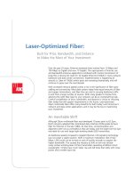
Figure 2. TIA-942 Compliant Data Center
Designing an Optimized Data Center
Page 4
Entrance Room
The entrance room houses carrier equipment and the
demarcation point. It may be inside the computer room,
but the standard recommends a separate room for
security reasons. If it’s housed in the computer room, it
should be consolidated within the main distribution area.
Main Distribution Area
The MDA houses the main cross-connect, the central
distribution point for the data center’s structured cabling
system. This area should be centrally located to prevent
exceeding recommended cabling distances and may
include a horizontal cross-connect for an adjacent
equipment distribution area. The standard specifies
separate racks for fiber, UTP, and coaxial cable.
Horizontal Distribution Area
The HDA is the location of the horizontal cross-
connects, the distribution point for cabling to equipment
distribution areas. There can be one or more HDAs,
depending on the size of the data center and cabling
requirements. A guideline for a single HDA is a maximum
of 2000 4-pair UTP or coaxial terminations. Like the
MDA, the standard specifies separate racks for fiber, UTP,
and coaxial cable.
Zone Distribution Area
This is the structured cabling area for floor-standing
equipment that cannot accept patch panels. Examples
include some mainframes and servers.
Equipment Distribution Area
This is the location of equipment cabinets and racks. The
standard specifies that cabinets and racks be arranged
in a “hot aisle/cold aisle” configuration to effectively
dissipate heat from electronics. See page 11 for a
discussion on cooling.
Space and Layout
Figure 3. Data Center with Flexible White Space
Designing an Optimized Data Center
Page 5
Cable Management
The key to cable management in the optimized data center is understanding that the cabling system is permanent and
generic. It’s like the electrical system, a highly reliable and flexible utility that you can plug any new application into.
When it’s designed with this vision in mind, additions and changes aren’t difficult or disruptive.
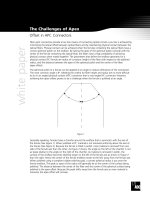
Key Principles
Highly reliable and resilient cabling systems adhere to the following principles:
• Common rack frames are used throughout the main distribution and horizontal distribution areas to simplify
rack assembly and provide unified cable management.
• Common and ample vertical and horizontal cable management is installed both within and between rack frames
to ensure effective cable management and provide for orderly growth.
• Ample overhead and underfloor cable pathways are installed—again, to ensure effective cable management and
provide for orderly growth.
• UTP and coaxial cable are separated from fiber in horizontal pathways to avoid crushing fiber—electrical cables
in cable trays and and fiber in troughs mounted on trays.
• Fiber is routed using a trough pathway system to protect it from damage.
Figure 4. Elements of Cable Management
Designing an Optimized Data Center
Page 6
Racks and Cabinets
Cable management begins with racks and cabinets,
which should provide ample vertical and horizontal
cable management. Proper management not only keeps
cabling organized, it also helps keep equipment cool
by removing obstacles to air movement. These cable
management features should protect the cable, ensure
that bend radius limits are not exceeded, and manage
cable slack efficiently (Figure 5).
It’s worth doing a little math to ensure that the rack or
cabinet provides adequate cable management capacity.
The formula for Category 6 UTP is shown below. The
last calculation (multiplying by 1.30) is done to ensure
that the cable management system is no more than 70
percent full.
Formula Cables x 0.0625 square inches (cable
diameter) x 1.30 = Cable Management
Requirement.
Example 350 cables x .0.0625 x 1.30 = 28.44 square
inches (minimum cable management of
6” x 6” or 4” x 8)
Cable Routing Systems
A key to optimized cable routing is ample overhead
and under floor cable pathways. Use the under floor
pathways for permanent cabling and the overhead for
temporary cabling. Separate fiber from UTP and coaxial
to ensure that the weight of other cables doesn’t crush
the more fragile fiber.
Figure 5. Cable Racks
Cable Management
Designing an Optimized Data Center
Page 7
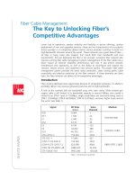
Ideal Rack and Cable Routing System
What is an ideal rack and cable routing system? Figure 6 is an illustration of ADC’s vision. Here are some key features:
1. The FiberGuide
®
assembly is mounted to the overhead cable racking and protects fiber optic cabling.
2. Express Exits
™
units are mounted where they are needed, allowing flexible expansion or turn-up of new network
elements.
3. Upper and lower cable troughs are used for patch cords and jumpers, and an overhead cable rack is used for
connection to equipment located throughout the data center.
4. Eight-inch Glide Cable Manager with integrated horizontal cable management organizes cables and aids in accurate
cable routing and tracing
5. Racks are equipped with 3.5-inch upper troughs (2 RUs) and 7-inch lower troughs (4RUs), providing adequate space
for cable routing.
6. Eight-inch vertical cable managers are shown. Six-, ten-, and 12-inch cable managers are also options, to best meet
the specific requirements of the data center installation and applications.
7'-0"
24"
DSX-1
DSX-3
Raised Floor
Structural Floor
FIBER
ETHERNET
Raised Floor
Supports Not
Shown for
Clarity
6
1
2
3
4
5
Figure 6. Fully-Populated, Fully-Integrated Lineup
Designing an Optimized Data Center
Page 8
Direct Connect
In the data center, direct connection (Figure 7) is not a
wise option because when changes occur operators are
forced to locate cables and carefully pull them to a new
location, an intrusive, expensive, unreliable, and time-
consuming effort. Data centers that comply with TIA-942
do not directly connect equipment.
Interconnect
When change occurs with an interconnect connection
(Figure 8), operators reroute end system cables to reroute
the circuit. This is far more efficient than the direct
connect method, but not as easy or reliable as the cross-
connect method.
Direct Connect Cable
ServerSwitch
Cable
Server
Patch Panel
Cable
Switch
Permanent
Cable
Jumper/
Patch Cord
Permanent
Cable
Ethernet
Distribution
Frame
Patch Panel
Patch Panel
Switch
Server
Introduction to Connection Methods
The industry recognizes three methods of connecting equipment in the data center: direct connect, interconnect, and
cross-connect. Only one of these, however – cross-connect – adheres to the vision of the cabling system as a highly-
reliable, flexible and permanent utility.
Cross-Connect
With a centralized cross-connect patching system, achieving the dual requirements of lower costs and highly reliable
service is possible. In this simplified architecture, all network elements have permanent equipment cable connections
that are terminated once and never handled again. Technicians isolate elements, connect new elements, route around
problems, and perform maintenance and other functions using semi-permanent patch cord connections on the front of
a cross-connect system, such as the ADC Ethernet Distribution Frame shown in Figure 9. Here are a few key advantages
provided by a well-designed cross-connect system:
• Lower operating costs: Compared to the other approaches, cross-connect greatly reduces the time it takes for adding
cards, moving circuits, upgrading software, and performing maintenance.
• Improved reliability and availability: Permanent connections protect equipment cables from daily activity that can
damage them. Moves, adds, and changes are effected on the patching field instead of on the backplanes of sensitive
routing and switching equipment, enabling changes in the network without disrupting service. With the ability to
isolate network segments for troubleshooting and reroute circuits through simple patching, data center staff gains
time for making proper repairs during regular hours instead of during night or weekend shifts.
• Competitive advantage: A cross-connect system enables rapid changes to the network. Turning-up new service is
accomplished by plugging in a patch cord instead of the labor-intensive task of making multiple hard-wired cable
connections. As a result, cards are added to the network in minutes instead of hours, decreasing time to revenue and
providing a competitive edge—faster service availability.
Figure 7. Direct Connect Figure 8. Interconnect
Figure 9. Cross-Connect
Designing an Optimized Data Center
Page 9
Fiber Optics: An Introduction
The benefits of fiber optic cabling are well known. It’s indispensable for bandwidth hungry applications, environments
where high levels of EMI are likely, and cable runs that exceed the recommended distances for copper. To get the most
from your investment in this valuable resource, however, it needs to be managed properly.
Plan for Growth
Data center personnel often underestimate their
requirements for fiber optic cabling, believing that
the first few strands are the end of it. That’s seldom
true. The best practice is to assume that your fiber
requirements will grow and to plan to handle that
growth efficiently.
Handling Considerations
Fiber is far from the delicate medium imagined by some.
It can be broken, however, if it is bent beyond the bend
diameter specified by the manufacturer. To prevent this,
effective fiber management systems should provide:
• Routing paths that reduce the twisting of fibers
• Access to the cable so that it can be installed or
removed without inducing excessive bends in
adjacent fiber
• Physical protection of the fiber from accidental
damage by technicians and equipment
Splicing vs. Field Connectorization
There are two methods for connecting strands of fiber,
splicing and field connectorization. The best choice
depends on the application. For short runs of multimode
fiber, using field connectorization is a good choice. It is
also an alternative for temporary connections. Otherwise,
splicing is the preferred method for the following
reasons:
• Lower signal loss:
Field-terminated connectors
– under the best circumstances – offer 0.25 dB signal
loss. Loss from fusion splicing is typically 0.01dB.
• More predictable results:
Anecdotal evidence
indicates that as many as 50 percent of field-installed
connectors fail when done by green technicians.
• Speed:
Trained technicians can splice two strands of
fiber together in as little as 30 seconds or six minutes
for two 12-strand fiber bundles.
Designing an Optimized Data Center
Page 10
Power
Requirements
Electricity is the life blood of a data center. A power
interruption of even a fraction of a second is enough to
cause a server failure. To meet demanding availability
requirements, data centers often go to great lengths
to ensure a reliable power supply. Common practices
include:
• Two or more power feeds from the utility company
• Uninterrupted power supplies (UPS)
• Multiple circuits to computing and communications
systems and to cooling equipment
• On-site generators
The measures you employ to prevent disruptions will
depend on the level of reliability required and, of course,
the costs. To help you sort through the tradeoffs, the
Uptime Institute, an organization concerned with
improving data center performance, has developed
a method of classifying data centers into four tiers,
with Tier I providing the least reliability and Tier IV the
most. Use this system, which is described briefly in the
following table, to help you sort through the tradeoffs.
Estimating Power Requirements
Estimating the data center power needs involves the
following steps:
1. Determine the electrical requirements for the servers
and communication devices that are in use now.
You can get this information from the device’s
nameplate. While the nameplate rating isn’t a perfect
measurement, it is the best data available to you.
2. Estimate the number of devices required to
accommodate future growth and assume that these
new devices will require the average power draw of
your current equipment. Be sure that this estimate
includes equipment that will supply the level of
redundancy required by your data center. While
estimating future needs is a difficult and imprecise
exercise, it will provide better guidance on future
needs than any other method.
3. Estimate the requirements for support equipment,
such as power supplies, conditioning electronics,
backup generation, HVAC equipment, lighting, etc.
Again, be sure that this estimate includes redundant
facilities where required.
4. Estimate the power requirements for this support
equipment.
5. Total the power requirements from this list.
Tier Description Availability
I
Tier I centers risk disruptions from planned and unplanned events. If they have a UPS or an engine generator, they are single-
module systems with many single points of failure. Maintenance will require a shutdown and spontaneous failures will cause
data center disruption.
99.671%
II
Tier II centers are slightly less susceptible to disruptions than Tier I centers because they have redundant components.
However, they have a single-threaded distribution path, which means that maintenance on the critical power path and other
infrastructure parts will require a shutdown.
99.741%
III
Tier III centers can perform planned maintenance work without disruption. Sufficient capacity and distribution are available to
simultaneously carry the load on one path while performing maintenance on the other. Unplanned activities, such as errors in
operation or spontaneous failures of components will still cause disruption.
99.982%
IV
Tier IV centers can perform any planned activity without disruption to the critical load and sustain at least one worst-case
unplanned failure with no critical load impact. This requires simultaneously active distribution paths. Electrically, this means two
separate UPS systems in which each system has N+1 redundancy. Tier IV requires all computer hardware to have dual power
inputs. Because of fire and electrical safety codes, there will still be downtime exposure due to fire alarms or people initiating
an Emergency Power Off (EPO).
99.995%
Designing an Optimized Data Center
Page 11
Cooling
Servers, storage area devices, and communications
equipment are getting smaller and more powerful.
The tendency is to use this reduced footprint to cram
more gear into a smaller space, thus concentrating an
incredible amount of heat. Dealing with this heat is
a significant challenge. Adequate cooling equipment,
though a start, is only part of the solution. Air flow is also
critically important. To encourage air flow, the industry
has adopted a practice known as “hot aisle/cold aisle.”
In a hot aisle/cold aisle configuration, equipment racks
are arranged in alternating rows of hot and cold aisles.
In the cold aisle, equipment racks are arranged face to
face. In the hot aisle, they are back to back. Perforated
tiles in the raised floor of the cold aisles allow cold air to
be drawn into the face of the equipment. This cold air
washes over the equipment and is expelled out the back
into the hot aisle. In the hot aisle, of course, there are no
perforated tiles, which keep the hot air from mingling
with the cold. For the best results with this method, aisles
should be two tiles wide, enabling the use of perforated
tiles in both rows if required.
This practice has met with wide industry acceptance.
In fact, it’s part of the TIA-942 recommendation.
Unfortunately, it’s not a perfect system. While it’s
common for equipment to exhaust heat out the back,
it’s not a universal practice. Some equipment draws cold
air in from the bottom and discharges the heated air out
the top or sides. Some brings in cold air from the sides
and exhausts hot air out the top. If additional steps are
required, other things to try include:
• Spreading equipment out over unused portions of
the raised floor. Obviously, this is an alternative only if
unused space is available.
• Increasing the height of the raised floor. Doubling floor
height has been shown to increase air flow as much as
50%.
• Using open racks instead of cabinets. If security
concerns or the depth of servers makes using racks
impossible, cabinets with mesh fronts and backs are
alternatives.
• Increasing air flow under the floor by blocking all
unnecessary air escapes.
• Replacing existing perforated tiles with ones with
larger openings. Most tiles come with 25% openings,
but some provide openings of 40 to 60%.
Power Cables
Telecom
Cable Trays
Power Cables
Perforated
Tiles
Telecom
Cable Trays
Cabinets
Rear
Front
Cabinets
Rear
Front
Cabinets
Rear
Front
Perforated
Tiles
Conclusion
The optimized data center is a well-designed system, each of its component parts working together to
ensure reliable access to the center’s resources while providing the flexibility needed to meet unknown
future requirements. Neglecting any aspect of the design is likely to leave the data center vulnerable
to very costly failure or to early obsolescence. This white paper has addressed several key design
considerations and offered the following recommendations:
•
Space: Ensure that there is enough of it and allocated flexibly to meet both current and future needs.
•
Cable Management: Treat the cabling system as a permanent and generic utility, a highly reliable
and flexible resource that can easily accommodate any new application.
•
Power: It’s the life blood of the data center. Build the level of redundancy needed to meet your data
center’s access requirements.
• Cooling:
Cooling equipment isn’t your only concern in this area. Air flow strategies also play a
significant role.
For More Information
See the following web sites for more information on data center issues.
For information on See the following
TIA-942 The TIA website (www.tiaonline.org/standards)
General data center reliability issues, including
power and cooling
The Uptime Institute (www.upsite.com)
ADC IP Infrastructure Solution www.adc.com/IP
Web Site: www.adc.com
From North America, Call Toll Free: 1-800-366-3891 • Outside of North America: +1-952-938-8080
Fax: +1-952-917-3237 • For a listing of ADC’s global sales office locations, please refer to our web site.
ADC Telecommunications, Inc., P.O. Box 1101, Minneapolis, Minnesota USA 55440-1101
Specifications published here are current as of the date of publication of this document. Because we are continuously
improving our products, ADC reserves the right to change specifications without prior notice. At any time, you may
verify product specifications by contacting our headquarters office in Minneapolis. ADC Telecommunications, Inc.
views its patent portfolio as an important corporate asset and vigorously enforces its patents. Products orfeatures
contained herein may be covered by one or more U.S. or foreign patents. An Equal Opportunity Employer
101818AE 12/05 Revision © 2004, 2005 ADC Telecommunications, Inc. All Rights Reserved
WHITE PAPER