Tài liệu TrueNet® Structured Cabling Solutions pdf
Bạn đang xem bản rút gọn của tài liệu. Xem và tải ngay bản đầy đủ của tài liệu tại đây (29.11 MB, 418 trang )
2nd Edition
TrueNet
®
Structured Cabling Solutions
Introduction 3
Technical Reference
Industry Standards
6
How to Choose the Right Cabling Infrastructure
19
10Gigabit Ethernet over UTP: CopperTen
™
Cabling Solution 22
Choosing the Right Ethernet Patch Panels
26
Designing the Optimized Data Center
31
Key Fiber Optic Cable Management Concepts
36
Power-over-Ethernet Solutions
Midspan Power-over-Ethernet Controller
40
Four-Port Midspan Power-over-Ethernet Unit
43
Four-Circuit Midspan Power-over-Ethernet Unit
44
Copper Cable Solutions
Introduction
46
Augmented Category 6 Horizontal Cable
CopperTen
™
Category 6A Plenum Data Cable 47
CopperTen
™
Category 6A Riser Data Cable 48
Category 6 Horizontal Cable
Plenum
49
Riser
52
Bundled Plenum
55
Bundled Riser
58
Limited Combustible
61
Category 5e Horizontal Cable
Plenum
64
Riser
67
Bundled Riser
70
The Outback Outdoor Cable
73
Category 5 Backbone Cable
25-pair Plenum
76
25-pair Riser
78
Category 3 Horizontal and Backbone Cable
Plenum
80
Riser
82
Horizontal and Backbone Cable
Category 1 UTP Plenum
84
Category 1 UTP Riser
86
Copper Connectivity Solutions
CopperTen
™
: Augmented Category 6 Solutions
Introduction
90
CopperTen
™
Patch Panels 91
CopperTen
™
Termination Blocks 92
CopperTen
™
Patch Cords 93
CopperTen
™
Modular Jack 94
CopperTen
™
Faceplate 95
CopperTen
™
Surface Mount Box 96
3 / 0 6 • 1 0 2 0 9 4 A E
TrueNet
®
Structured Cabling
Table of Contents
w w w . a d c . c o m • + 1 - 9 5 2 - 9 3 8 - 8 0 8 0 • 1 - 8 0 0 - 3 6 6 - 3 8 9 1
Table of Contents
Category 6 Solutions
Introduction
98
Patch Panels
24-Port
100
48-Port
100
6-Port
100
Blank Panel
100
Dynamic Angle Right/Left Panel
24-Port
101
48-Port
101
Plug ‘n’ Play Patch Panel
24-Port Patch Plus
103
High-Density Plug ‘n’ Play
103
Label Sheets
103
Ultim8
™
Termination Block System
Wire Termination Block
104
Field Assembly Kits
96-Pair
105
160-Pair
105
168-Pair
105
HighBand
®
25 Termination Block Systems
Wire Termination Blocks
300-Pair Basic System
107
900-Pair Basic System
107
300-Pair Cable Management Kit
107
900-Pair Cable Management Kit
107
Block with Rear Cable Manager
107
25-Pair Voice Module
107
Label Holder
108
Back Mount Frame
108
Cable Trough
108
Cable Management Rings
108
Rack Mount Frame
108
Patch Cords
RJ45 Plug to RJ45 Plug
109
For Ultim8
™
Blocks 110
For HighBand
®
25 Blocks 112
KM8 Modular Jacks
113
Category 5e Solutions
Introduction
116
Patch panels
24-Port
118
48-Port
118
Dynamic Angle Right/Left
24-Port
119
48-Port
119
Plug ‘n’ Play Patch Panel
24-Port Patch Plus
121
High-Density Plug ‘n’ Play
121
Label Sheets
121
3 / 0 6 • 1 0 2 0 9 4 A E
TrueNet
®
Structured Cabling
Table of Contents
w w w . a d c . c o m • + 1 - 9 5 2 - 9 3 8 - 8 0 8 0 • 1 - 8 0 0 - 3 6 6 - 3 8 9 1
Table of Contents
UMS/Mini Patch Panels
6-Port
122
Patch Cords
123
HighBand
®
10 Termination Block System
10-pair Blocks
124
Field Assembly Kits
125
K610 Series Jacks
126
Specialty Copper Connectivity Products
Ethernet Test Access Panel
128
T1 Demarcation Modular Patch Panels
129
RJ45 Coupler Panel
130
Fast Ethernet Patch Panels
131
25-Pair Cable Assemblies
RJ21x/RJ21x
132
RJ21x/Hydra
132
HighBand
®
10 Collocation Block Systems
100-Pair
134
200-Pair
134
300-Pair
134
Feed-Thru (FT) Termination Blocks
4-Pair Color-Coded Block
136
5-Pair Color-Coded Block
136
Type 160 Hinged Label Holder
136
Label Sheets
136
Field Assembly Kits
100-Pair, 4-Pair Color-Coded
138
100-Pair, 5-Pair Color-Coded
138
300-Pair, 4-Pair Color-Coded
138
300-Pair, 5-Pair Color-Coded
138
Patch Cords
139
Test Shoe
141
Test Cord
141
Copper Cable Management Solutions
Ethernet Distribution Frame
144
Glide Cable Manager
Glide Cable Manager, Vertical Mount
146
Hinged Black Metal Cover Kit
146
Glide Cable Manager, Cabinet Mount
146
Crossover Troughs
147
Horizontal Cable Managers
147
Rear Cable Management Bar
147
Slack Manager
147
Stabilizers
147
Extender Brackets
147
7' Equipment Racks
147
Universal Mounting System (UMS) Introduction
148
Universal Mounting System (UMS)
149
Basic Kit
149
Vertical Cable Manager
151
3 / 0 6 • 1 0 2 0 9 4 A E
TrueNet
®
Structured Cabling
Table of Contents
w w w . a d c . c o m • + 1 - 9 5 2 - 9 3 8 - 8 0 8 0 • 1 - 8 0 0 - 3 6 6 - 3 8 9 1
Table of Contents
Horizontal Wire Manager 151
BackBoard
152
High Volume Cable Managers
19" Cable Manager
153
23" Cable Manager
153
35.5" Cable Manager
153
6.5" Cable Manager
153
9" Cable Manager
153
Back Mount Frames
Type 85 Back Mount Frames
154
Type 105 Back Mount Frames
155
Type 105 Back Mount Frame with Ground Lug
156
Rod Mount Frames
Type 85 Rod Mount Brackets
157
Type 105 Rod Mount Brackets
158
Rod Mount Spacer
158
Wall or Rack Mount Mounting Frames
19" Mounting Frame
159
23" Mounting Frame
159
35.5" Mounting Frame
159
Wall or Rack Mount Support Bars
19" Support Bar
160
23" Support Bar
160
35.5" Support Bar
160
Type 85 and Type 105 Inverted Support Bars
161
Jumper Rings
19" Jumper Ring Bar
162
23" Jumper Ring Bar
162
35.5" Jumper Ring Bar
162
Accessories
Vertical Cable Organizer
164
Horizontal Cable Organizer
164
Rear Wire Management Guide
164
High-Density Cable Manager
164
Ring Wire Manager
164
Hinged Wall Mount Bracket
164
Copper Connectivity Accessories and Labels
Accessories
HighBand
®
10 to Series 2 Adapter 166
Red Dummy Plug
166
Red Marking Cap
166
Disconnect Plug
166
Bridging Test Cord
166
“Look-Both-Ways” Test Cord
166
Winged Test Adapter
166
Labeling
Labeling for Category 5e and Category 6 Patch Panels
167
Type 105 Label Strip
168
Type 105 Label Holder
168
Type 105 Hinged Label Holder
169
3 / 0 6 • 1 0 2 0 9 4 A E
TrueNet
®
Structured Cabling
Table of Contents
w w w . a d c . c o m • + 1 - 9 5 2 - 9 3 8 - 8 0 8 0 • 1 - 8 0 0 - 3 6 6 - 3 8 9 1
Table of Contents
Paper Labels 171
TIA/EIA-606 Color-Coding
171
Label Sheet for Type 105 Hinged Label Holder
171
Label Sheet for Type 105 Label Holder
171
Label Sheet for Type 105 Label Strip
171
Work Area Solutions
Introduction
174
Category 6A Modular Jacks
175
Category 6 KM8 Modular Jacks
176
Category 5e K610 Series Jacks
177
Modular Adapters
F-81 Adapter
179
MTRJ Adapters
179
SC Multimode/Singlemode Adapters
179
ST
®
Multimode/Singlemode Adapters 179
BNC Adapter
179
S-Video Adapter
179
RCA Adapter
179
Blank Modular Insert
179
Angled Port Faceplates
4-Port
180
8-Port
180
Faceplate Extender
180
Flush Mount Faceplates
Single-Gang
2-Port
182
4-Port
182
6-Port
182
Dual-Gang
4-Port
182
8-Port
182
12-Port
182
Specialty Faceplates
Stainless Steel
184
Stainless Steel Wall Phone Plate
184
4-Port Walker Monument Faceplate
184
Drywall Faceplate Adapter
184
Electrical Faceplate 106 Adapter
184
Dual-Gang Surface Mount Box
184
Decorative Faceplates
185
Modular Furniture Faceplates
3-Port
187
4-Port
187
4-Port Beltline Adapter
187
2-Port Horizontal
187
Surface Boxes
2-Port
188
4-Port
188
6-Port
188
3 / 0 6 • 1 0 2 0 9 4 A E
TrueNet
®
Structured Cabling
Table of Contents
w w w . a d c . c o m • + 1 - 9 5 2 - 9 3 8 - 8 0 8 0 • 1 - 8 0 0 - 3 6 6 - 3 8 9 1
Table of Contents
Surface Box for Modular Furniture
12-Port
189
Mounting Accessories
189
Specialty Boxes
Multimedia Box
Multimedia Box
190
Empty Bezels
190
Mounting Magnets
190
All-Fit Specialty Box
6-Port
192
4-Port
192
Steel Cover
192
Duplex SC Bezel
192
Surface Mount Box
192
Magnet Strip
192
Accessories
KM8 Termination Tool
193
Termination Puck
193
ID Tabs
193
Paper Labels for Faceplates
193
Concealed Entrance Outlets
194
Fiber Cable Solutions
Introduction
196
OSP Cable
I/O Dry Loose Tube – Riser/Plenum
198
I/O Riser
200
Compact Building Cables
Plenum
202
Riser
204
Breakout Cables: Riser and Plenum
206
Closet Distribution LCF Optical Cable (Heavy Metal/Lead-Free)
Plenum
208
Riser
211
Furcation Tubing
214
Next Generation Frame – High Density Fiber Solutions
Introduction & Applications
218
Fiber Main Distributing Frame
219
Fiber Termination Blocks & Accessories
Fiber Termination Blocks (FTB) – Adapter Only
220
Cable Clamping Block Conversion Kit
221
Fiber Termination Blocks (FTB) – Preterminated with IFC or OSP Cable
222
Fiber Combination Blocks (FCB)
224
Sliding Adapter Packs
226
Accessories
End Guard
228
Cable Clamp Kit
228
Rack Installation Kit
228
3 / 0 6 • 1 0 2 0 9 4 A E
TrueNet
®
Structured Cabling
Table of Contents
w w w . a d c . c o m • + 1 - 9 5 2 - 9 3 8 - 8 0 8 0 • 1 - 8 0 0 - 3 6 6 - 3 8 9 1
Table of Contents
Fiber Connectivity Solutions
Fiber Enclosure Products
FL2000 System
Preconfigured Termination/Splice Panels
234
Preconfigured Termination Only Panels
235
Preconfigured Termination/Splice Panels with Two Adapter Styles
236
Preconfigured Termination Panels with MTRJ Adapters
237
Preconfigured Termination Panels with Multifiber Cable
239
Empty Termination Panels
241
Empty Splice Panels
242
Empty Termination/Splice Panels
243
6pak Connector Plug-Ins with Adapters and Pigtails
244
6pak Connector Plug-Ins with Adapters only
245
FL2000 Mounting Options
19" (48.26cm) Rack Mounting: Standard and Flush Mount
246
19" (48.26cm) Rack Maximum Mounting
247
FPL Series Fiber Panels
1 Rack Unit FPL
249
Preconfigured Termination Only Panels
251
Preconfigured Termination Panels with Multifiber Cable
253
Preconfigured Termination/Splice Panels
255
Preconfigured High Density Termination/Splice Panels
257
Fiber Management Trays
1 Rack Unit Slack Storage
261
1 Rack Unit Termination/Splice Fixed Bulkhead
263
1 Rack Unit Termination and Storage Fixed Bulkhead
264
1 Rack Unit Specifications
265
2 Rack Unit Termination with Adapters Only
266
2 Rack Unit Termination with Multifiber Cable
267
2 Rack Unit Termination/Splice
268
2 Rack Unit Micro Value – Added Module System
269
2 Rack Unit Micro Value – Added Module System Monitor Module
270
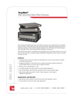
RMG Series Rack Mount Fiber Enclosures
Specifications
273
Pre-Configured Panels with Adapters and/or Pigtails
274
Empty Panels
275
Modular Adapter Paks
276
Modular MTP/MPO Cassettes
278
WMG Series Wall Mount Fiber Enclosures
Pre-Configured Enclosures with Adapters and/or Pigtails
280
Empty Enclosures
281
Modular Adapter Paks
282
Fiber Optic Specifications
284
Fiber Optic Patch Cords
Multimode
285
Singlemode
286
Multifiber Patch Cords
287
Fiber Connectivity Accessories
Fiber Connector/Adapter Cleaning Kit
288
Fiber Optic Connectors
Epoxy/Polish Connectors
289
Field Installation Connectors
291
3 / 0 6 • 1 0 2 0 9 4 A E
TrueNet
®
Structured Cabling
Table of Contents
w w w . a d c . c o m • + 1 - 9 5 2 - 9 3 8 - 8 0 8 0 • 1 - 8 0 0 - 3 6 6 - 3 8 9 1
Table of Contents
Fiber Cable Raceway System
Standard FiberGuide
®
Fiber Management System
Patch Cord Densities
296
Express Exits
™
Units 297
2x2 System
297
2x6 System
298
4x4 System
299
4x4 and 4x6 Downspout Options
300
2x6, 4x4 and 4x6 Support Kits
300
4x6 System
301
4x12 System
302
Vertical Duct System
303
Flex Tubing
303
Accessories
303
Plenum FiberGuide
®
System
Patch Cord Density
306
2x2 System
307
4x6 System
308
4x12 System
309
Accessories
309
Complementary Products
Voice Grade Solutions
Series 2 Wire Termination Block System
8-Pair Block
312
10-Pair K110 Disconnect Block
312
10-Pair Block
312
Field Assembly Kits
160-Pair
314
200-Pair
314
300-Pair
314
Preterminated Assemblies
160-Pair
316
168-Pair
316
200-Pair
316
300-Pair
317
Preterminated Blocks
200-Pair
318
300-Pair
318
Stubbed Disconnect Blocks
100-Pair
319
200-Pair
319
8-Pair Termination Block System
320
Grounding Blocks
Grounding Block
322
Ground Clips
322
Rod Mount/Back Mount Frame Ground Kit
322
Category 5 Patch Cords
323
Labeling
Type 85 Label Holder
325
Type 85 Rod Mount Label Holder
325
3 / 0 6 • 1 0 2 0 9 4 A E
TrueNet
®
Structured Cabling
Table of Contents
w w w . a d c . c o m • + 1 - 9 5 2 - 9 3 8 - 8 0 8 0 • 1 - 8 0 0 - 3 6 6 - 3 8 9 1
Table of Contents
Type 85 Hinged Label Holder 325
Type 85 Label Strip
325
Side-Mount Label Holder
325
Type 105 Label Holder
325
Type 105 Hinged Label Holder
325
Type 105 Slotted Label Strip
325
Label Sheet for Type 85 Rod Mount Label Holder
327
Label Sheet for Type 85 Label Holder, Hinged Label Holder or Label Strip
327
Label Sheet for Type 105 Hinged Label Holder
327
Label Sheet for Type 105 Label Strip
327
Accessories
Disconnect Plug
329
Flat-Top Dummy Plugs
329
Marking Caps
329
Ground Clips
329
Cable Clamp
329
Disconnect Bars
329
200-Pair Dust Cover
330
Winged Test Adapter
330
Signature Device
330
Test Cords
330
“Look-Both-Ways” Test Cord
330
Site-Mounted Test Cord
NT Termination Block System
Disconnect Block
332
Switching Block
332
Connect Block
332
Ground Block
332
NT to Series 2 Adapter
332
Dummy Plug
332
Marking Caps
332
Disconnect Plug
332
Hinged Label Holder
332
Label Holder
332
5-Position Back Mount Frame
333
10-Position Back Mount Frame
333
20-Position Back Mount Frame
333
30-Position Back Mount Frame
333
KRONE Insertion Tool
334
89D Style Termination Blocks and Assemblies
25-Pair Disconnect Block Assembly
335
50-Pair Disconnect Block Assembly
335
5-Pair Disconnect Block
335
25-Pair Disconnect Block with RJ-21X Connector
336
25-Pair Disconnect Block with RJ-71C
336
25-Pair Disconnect Block with RJ48X Connectors
337
25-Pair Disconnect Block with RJ48S Connectors
338
25-Pair Disconnect Block with RJ48C Connectors
338
25-Pair Disconnect Block with RJ48S and RJ-21X Connectors
339
25-Pair Disconnect Block with RJ14C and RJ-21X Connectors
339
50-Pair Disconnect Block with RJ-21x Connectors
340
3 / 0 6 • 1 0 2 0 9 4 A E
TrueNet
®
Structured Cabling
Table of Contents
w w w . a d c . c o m • + 1 - 9 5 2 - 9 3 8 - 8 0 8 0 • 1 - 8 0 0 - 3 6 6 - 3 8 9 1
Table of Contents
50-Pair Disconnect Block with RJ48X Connectors 341
50-Pair Disconnect Block with RJ48X Connectors Modified for Shielded Applications
341
50-Pair Disconnect Block with RJ48C Connectors
342
50-Pair Disconnect Block with RJ45 Connectors
342
50-Pair Disconnect Block with ARMM Stub
343
50-Pair Disconnect Block with ARMM Stub and RJ-21x Connectors
343
900-Pair Disconnect Frame with ARMM Stub
344
Mounting Frames
19" Mounting Frame
345
23" Mounting Frame
345
35.5" Mounting Frame
345
Accessories
50-Pair Block Center Mount Label Holder
346
Clear Dust Cover
346
Labeling Strip for Dust Cover
346
Hinged Dust Cover
346
Stand off Bracket
346
Disconnect Plug
347
Flat-Top Dummy Plugs
347
Building Entrance Terminals
NEMA 4x-Classified Fiber Wall Mount Box
348
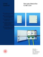
NEMA Fiber Demarcation Box (FDB)
With Pigtails
351
With Multifiber Cable
352
High-Density 5-Pin Protection
25-Pair
355
50-Pair
355
100-Pair
355
5-Pin Indoor and Outdoor Enclosed Building Entrance Terminals
25-Pair
357
50-Pair
357
100-Pair
357
10-Pair Magazine Protection
25-Pair
359
50-Pair
359
100-Pair
359
10-Pair Magazine Protection Indoor and Outdoor Enclosed Building Entrance Terminals
100-Pair Indoor
361
100-Pair Outdoor
361
10-Pair Protection Magazine with Fail-Safe
362
Single-Pair Protectors
25-Pair Building Entrance Terminal
364
50-Pair Building Entrance Terminal
364
100-Pair Building Entrance Terminal
364
Single-Pair Solid-State Protector Units
365
Media Conversion Solutions
OptEnet
™
Modular Chassis
Introduction
367
Applications
368
Modular Chassis
369
Power Supply Modules
370
3 / 0 6 • 1 0 2 0 9 4 A E
TrueNet
®
Structured Cabling
Table of Contents
w w w . a d c . c o m • + 1 - 9 5 2 - 9 3 8 - 8 0 8 0 • 1 - 8 0 0 - 3 6 6 - 3 8 9 1
Table of Contents
Communications Modules
CPU
371
Alarm Card
371
Singlemode to Multimode Optical Conversion Line Card
372
10/100Mbps Optical Ethernet Conversion Line Card
374
Gigabit Ethernet Line Card
376
OptEnet
™
Work Station Media Converters
Introduction
379
Mouse Port Power Option
380
Wall Outlet Power Option
380
USB Port Power Option
380
RJ45 Patch Cords
380
OptEnet
™
Single-Mount Solution
Introduction
381
Application
382
Singlemode to Multimode, 10-622Mbps
383
10/100Mbps Optical Ethernet Conversion
383
1000Mbps Optical Ethernet Conversion
383
Wall Mount Bracket
383
Specifications
384
Other Enterprise Solutions
Power Distribution Products
385
Digital Signal Cross-Connect Products
385
Outside Plant Cabinets for Campus Applications
386
Sound and Video Solutions for Auditoriums and Surveillance Applications
387
Data Management and Access Products
387
Megabit Modem 702G2
388
Indoor Wireless Coverage Solutions
389
Index 391
3 / 0 6 • 1 0 2 0 9 4 A E
TrueNet
®
Structured Cabling
Table of Contents
w w w . a d c . c o m • + 1 - 9 5 2 - 9 3 8 - 8 0 8 0 • 1 - 8 0 0 - 3 6 6 - 3 8 9 1
Table of Contents
3 / 0 6 • 1 0 2 0 9 4 A E
TrueNet
®
Structured Cabling
w w w . a d c . c o m • + 1 - 9 5 2 - 9 3 8 - 8 0 8 0 • 1 - 8 0 0 - 3 6 6 - 3 8 9 1
Table of Contents
TrueNet
®
Structured Cabling Solutions
Introduction
ADC’s TrueNet
®
Structured Cabling System is the integrated portfolio of high-performance copper and
fiber cable, connectivity, and cable management products from ADC and KRONE. The precisely tuned
TrueNet system exceeds TIA/EIA standards and provides a clear path for uninterrupted data throughput
within the entire network.
True End-to-End Solutions
The TrueNet system delivers proven cable, connectivity, and cable management solutions for fiber,
10 Gigabit Ethernet over UTP, and Category 6/5e from the data center to the desktop.
Category 6 & 5e Ethernet
ADC's TrueNet Category 6 & 5e
patch panels, patch cords, and
cable are impedance matched to
deliver extra bandwidth and better
attenuation with zero bit errors.
Work Area Solutions
ADC’s high-performance modular
jacks are field-configurable for
flush, surface, and furniture
mounting applications.
Cable Management
Protect, route, and manage
network cables for optimized
signal integrity with ADC’s
portfolio of cable management,
labeling, and racking solutions.
Copper Cables
ADC’s high-performance riser and
plenum cable supports backbone
and horizontal applications. TrueNet
copper cables feature patented
AirES
®
technology to enhance
signal speed and strength while
minimizing cable size and crosstalk.
Media Conversion
Expand optical networks
while extending legacy copper
infrastructure. ADC’s OptEnet
™
Media
Converters transition and protect
critical Ethernet, OC-12, and GigE
circuitry throughout the network.
1
w w w . a d c . c o m • + 1 - 9 5 2 - 9 3 8 - 8 0 8 0 • 1 - 8 0 0 - 3 6 6 - 3 8 9 1
Introduction
Fiber Cables
Fiber cables including: cost
saving interlocked armored
versions, plenum rated dry
loose tube small diameter
Indoor/outdoor cables, single
mode reduced water peak, and
standard or laser optimized
multimode configurations.
NEW
Fiber Connectivity
In the backbone or to the desk,
optical networks achieve peak
performance with ADC’s high
density frames, fiber connectors,
patch cords, raceways, and
panels featuring integrated
cable management and bend
radius protection.
NEW
Power-over-Ethernet
Deliver power to VoIP phones,
Wi-Fi access points, and other
IP devices over the local area
network with ADC’s IEEE
802.3af-compliant Power-over-
Ethernet Midspan Controllers.
NEW
Augmented Category 6
ADC’s patent-pending CopperTen
™
Solution is the world's first
complete system to meet the IEEE
requirements for 10G Ethernet
over 100 meters of the UTP cable.
NEW
Applications Solutions
A global network infrastructure
leader, ADC offers complete
solutions for data centers,
storage area networks, central
offices, campuses, wireless and
Wi-Fi networks, and other high-
performance applications.
NEW
3 / 0 6 • 1 0 2 0 9 4 A E
TrueNet
®
Structured Cabling
2
w w w . a d c . c o m • + 1 - 9 5 2 - 9 3 8 - 8 0 8 0 • 1 - 8 0 0 - 3 6 6 - 3 8 9 1
Introduction
TrueNet
®
Structured Cabling Solutions
Introduction
True Performance
With TrueNet, you can push networks to the performance edge. Innovative products that exceed
industry standards support advanced applications such as 10GigE over UTP, VoIP, and Wi-Fi today and
tomorrow. Building upon a high-performance TrueNet infrastructure foundation, network managers and
designers are assured a flexible evolution path to next-generation technologies and services.
A Tradition of Innovation
With thousands of patents worldwide, ADC continually invests in innovation to support emerging
technologies and to enhance our customers’ network operations. In fiscal 2000 to 2003, ADC invested
approximately 13% of net sales to fuel research and development.
For example, ADC’s innovative CopperTen
™
solution is the world’s first Augmented Category 6 system
to deliver all internal requirements of Category 6 while achieving 18 Gb/s capacity as measured
by Shannon’s Law with extended frequencies up to 625MHz. To achieve these high-performance
specifications, CopperTen incorporates patent-pending features including a unique oblique filler that
minimizes alien crosstalk (interference from adjacent cables).
The company’s patent-pending AirES
®
technology is a critical element in the TrueNet CopperTen,
Category 6, and Category 5e solutions and results in the first and only cable design to increase
signal speed and strength while simultaneously minimizing crosstalk. AirES technology utilizes air as a
conductor insulator, eliminating the bulky fillers and extra bonding that increase cable weight, reduce
flexibility, and require extra space.
Setting the Standards
ADC’s TrueNet solutions meet or exceed all major cabling standards. We are actively establishing and
advocating next-generation technologies and standards worldwide through work with these leading
industry organizations:
TIA: Telecommunications Industry Association
EIA: Electronic Industries Alliance
IEEE: Institute of Electrical and Electronic Engineers
BICSI: Building Industry Consulting Service International
MEF: Metro Ethernet Forum
ISO: International Organization for Standardization
IEC: International Electrotechnical Commission
ANSI: American National Standards Institute
Training and Certification
Studies show that over 70% of network downtime can be directly attributed to physical layer problems,
specifically cabling faults. ADC recognizes that proper installation of structured cabling solutions is a
critical success factor for high-performance networks. ADC’s network of more than 400 TrueNet System
Certified contractors and installers undergoes annual extensive training to ensure that TrueNet system
installations meet the most stringent industry standards.
3 / 0 6 • 1 0 2 0 9 4 A E
TrueNet
®
Structured Cabling
3
w w w . a d c . c o m • + 1 - 9 5 2 - 9 3 8 - 8 0 8 0 • 1 - 8 0 0 - 3 6 6 - 3 8 9 1
Introduction
TrueNet
®
Structured Cabling Solutions
Introduction
True Reliability
Mission-critical networks rely upon trusted TrueNet infrastructure. Built and tested in ADC’s world-class
facilities, TrueNet is backed by the industry’s only true Zero Bit-Error Warranty that guarantees signal
integrity and throughput.
World-Class Manufacturing Expertise
ADC is committed to consistently delivering the highest possible quality in all that we do. A registered
TL9000 and ISO9000:2000 manufacturer, ADC is certified in 21 categories—the largest number of
registrations of any ISO-certified company. Additionally, ADC facilities are approved to self-certify
products for compliance with UL Safety Standards.
A best-in-class manufacturer, ADC operates more than 385,000 square feet of manufacturing space
in the Americas.
Backed by the TrueNet Warranty
ADC’s TrueNet system is backed by an industry-leading warranty that not only addresses physical
component performance, but also data throughput. Cable and connectivity solutions are tuned to
eliminate impedance mismatches to standards five times more rigorous than industry specifications.
As a result, TrueNet optimizes network speed by eliminating data retransmissions.
The TrueNet warranty covers all aspects of the structured cabling system for horizontal and backbone
networks that support voice and data. A 20-year all-inclusive industry standards compliance warranty
addresses all parts, labor, and technical support. And for certain TrueNet product categories, an
additional 5-year throughput warranty guarantees zero bit-error rate performance throughout the
structured cabling channel.
3 / 0 6 • 1 0 2 0 9 4 A E
TrueNet
®
Structured Cabling
4
w w w . a d c . c o m • + 1 - 9 5 2 - 9 3 8 - 8 0 8 0 • 1 - 8 0 0 - 3 6 6 - 3 8 9 1
Introduction
TrueNet
®
Structured Cabling Solutions
Introduction
About ADC
Founded in 1935, ADC has served the communications industry for more than half a century and today
is a leading supplier of global network infrastructure products and services. In 2004, ADC acquired the
KRONE Group, a leading global supplier of copper and fiber-based connectivity solutions and cabling
products. The integration of these two companies positions ADC with annual sales exceeding $1 Billion
and an employee base exceeding 7000 professionals worldwide.
The company conducts business in more than 100 countries and operates primary facilities in
Minneapolis, Minnesota; Denver, Colorado; Sidney, Nebraska; Bennington, Vermont; Santa Teresa, New
Mexico; Delicias and Mexico City, Mexico; Berlin, Germany; Glenrothes, Scotland; Chelthanham and
Richmond, Great Britain; Shanghai, China; Berkley Vale, Australia; Cotia, Brazil; and Bangalore, India.
Customers around the world include leading communications service providers and enterprises of all
types including Bank of England, BellSouth, Bloomberg, British Telecom, Chase Manhattan, Cingular,
CitiBank, Deutsche Telekom, Glaxo Smith Kline, Hong Kong Telecom, Morgan Stanley, Nextel, Reliance
Telecom (India), Qwest, T-Mobile, SBC, Seagrams, Sprint, Verizon, and many others.
Learn More About TrueNet Structured Cabling Solutions
Within this catalog, you’ll find complete descriptions and ordering information for the most popular
TrueNet Structured Cabling Solutions. Because we continually enhance our product portfolio and our
specifications, we encourage you to visit our web site or contact an ADC representative to keep pace
with the latest innovations.
3 / 0 6 • 1 0 2 0 9 4 A E
TrueNet
®
Structured Cabling
5
w w w . a d c . c o m • + 1 - 9 5 2 - 9 3 8 - 8 0 8 0 • 1 - 8 0 0 - 3 6 6 - 3 8 9 1
Technical Reference
Technical Reference
Industry Standards 6
How to Choose the Right Cabling Infrastructure 19
10Gigabit Ethernet over UTP 22
Choosing the Right Ethernet Patch Panels 26
Designing the Optimized Data Center 31
Key Fiber Optic Cable Management Concepts 36
3 / 0 6 • 1 0 2 0 9 4 A E
TrueNet
®
Structured Cabling
6
w w w . a d c . c o m • + 1 - 9 5 2 - 9 3 8 - 8 0 8 0 • 1 - 8 0 0 - 3 6 6 - 3 8 9 1
Technical Reference
Imagine trying to link railroads together that are based on different gauges, to build anything with
a combination of metric and American parts, to type a letter on something other than a QWERTY
keyboard, or to wire a building for voice, data and video if all the components had different requirements.
The key to simplifying all these tasks is standardization. Bringing standards to the wiring and cabling
segments of the building industry has enabled the industry to define a common infrastructure that allows
many companies to provide common components. Strict adherence to these standards benefits everyone.
ADC’s Position on Standards
ADC is a strong proponent of standards-based design for structured cabling systems. A strictly
defined set of standards helps ensure uniform application of physical layer networking products
and creates a usable infrastructure for communications networks.
However, ADC also believes that by nature, the standards evolve into a lowest-common denominator
indicator of performance. In order to accommodate various competing interests, a significant amount
of “flexibility” gets built into the allowable tolerances. The cumulative effect of these tolerances can
result in structured cabling channels in which different components can have radically different electrical
performance characteristics.
Consequently, when various standards-compliant components from randomly selected vendors are used,
the net result could be conformance to the standards, but not efficient performance.
The research undertaken by ADC for the TrueNet
®
structured cabling system revealed that only
a impedance-matched structured cabling channel that conforms to a tightly defined subset of the
performance standards is capable of flawless data transmission.
ADC, as a full system supplier, is able to deliver a complete system of impedance-matched components
so there is no guesswork. Choosing standards-compliant components randomly from unrelated vendors
will yield a standards-compliant channel, but may not result in optimum network performance.
Therefore, use the standards as a design guide, then make sure that you purchase standards-compliant
matched components.
Technical Reference
Industry Standards
The Benefits of Standards
Telecommunications
Rooms
Horizontal Cabling
Work Area
Entrance Facilities
and Equipment Rooms
Backbone Cabling
(Interbuilding)
Backbone Cabling
(Interbuilding)
The TIA/EIA-568-B Series standard defines a typical,
generic telecommunications cabling system.
Intermediate
Cross-Connects
Telecommunications
Rooms
Main Cross-Connect
3 / 0 6 • 1 0 2 0 9 4 A E
TrueNet
®
Structured Cabling
7
w w w . a d c . c o m • + 1 - 9 5 2 - 9 3 8 - 8 0 8 0 • 1 - 8 0 0 - 3 6 6 - 3 8 9 1
Technical Reference
Entrance Facilities
The entrance facility provides a connection point between the outside plant facilities—whether it is
public network services, private network customer premises or a combination of both—and the interior
premises cabling. Products used in this area include cables, connecting hardware, special protection
devices and other connecting hardware.
The demarcation point separating the service provider’s cabling and the customer’s cabling may be
part of the entrance facilities. Because the location of the demarcation point is determined by state
and federal regulations, the local regulated carrier (telephone service provider) or competitive access
provider should be contacted for detailed information.
The primary standards for this area are outlined in TIA/EIA-569-A, Commercial Building Standard
for Telecommunications Pathways and Spaces, and J-STD-607-A, Commercial Building Grounding/
Bonding Requirements.
ADC manufactures special overvoltage blocks, protection devices and building entrance terminals
for both fiber and copper cabling for use in this area.
Equipment Rooms
The TIA/EIA-568-B Series standard makes a distinction between equipment rooms and telecom-
munications rooms because of the nature of complexity of the equipment they contain. However, an
equipment room may alternately provide any or all of the functions of a telecommunications room.
Equipment rooms provide a controlled environment to house telecommunications equipment.
This equipment may include connecting hardware, splice closures, grounding and bonding facilities
and protection devices, where applicable. Switches, routers and other active equipment may reside
in the same rack or cabinet space as the passive cabling infrastructure.
In the premises cabling backbone hierarchy, an equipment room may contain either the main
cross-connect or the intermediate cross-connect. The equipment room may also contain network trunk
terminations and auxiliary terminations that are under the control of the premises cabling administrator.
The primary standards for this area are outlined in TIA/EIA-569-A, Commercial Building Standard
for Telecommunications Pathways and Spaces.
ADC manufactures a wide variety of fiber and copper patch panels, termination blocks and cable
management solutions that are well suited for this area.
Telecommunications Rooms
Telecommunications rooms may provide various functions for the cabling system and because of this
they are treated as a distinct subset in the cabling system hierarchy.
The primary function of a telecommunications room is to provide a termination point for horizontal
cable distribution, that supports all voice, data, video and other applications requiring structured
cabling. The telecommunications room also serves as a termination point for backbone cable.
The cross-connection of these two parts of the premises cabling is an important function of the
telecommunications room. Cross-connections may be accomplished using jumper wires or patch cords,
and ADC products handle both methods equally well.
Telecommunications rooms may also house cross-connects for different portions of the backbone
cabling system. These cross-connects are sometimes used to tie different rooms together in a ring, bus
or tree configuration.
Technical Reference
Industry Standards
3 / 0 6 • 1 0 2 0 9 4 A E
TrueNet
®
Structured Cabling
8
w w w . a d c . c o m • + 1 - 9 5 2 - 9 3 8 - 8 0 8 0 • 1 - 8 0 0 - 3 6 6 - 3 8 9 1
Technical Reference
Telecommunications rooms also provide a controlled environment for specific areas of a building. These
rooms may house telecommunications equipment, connecting hardware and splice closures as well as
devices such as routers and hubs. In some instances, the demarcation point and protection devices may
be located in a telecommunications room.
The TIA/EIA-568-B Series standard details cable routing and installation practices for telecommunications
rooms to prevent cable stress and to properly organize and manage cables.
Additional standards for this area are outlined in TIA/EIA-569-A, Commercial Building Standard for
Telecommunications Pathways and Spaces.
ADC manufactures a wide variety of blocks and patch panels capable of providing termination and
cable management for a wide range of wire sizes and cable types found in telecommunications rooms.
For More Information
Although this catalog presents a brief overview of information contained in the standard, persons
involved with the installation and maintenance of structured cabling systems should obtain a copy of
the complete standard and/or related standards.
Technical Reference
Industry Standards
FUSE
ON OFF
FUSE
ON OFF
Work Area
Work Area
Cable
Telcom
Outlet
Station
Field
Equipment
Field
Patch Cord
Data Hub
3M (Max) 90M (Max)
A + B < 10M
Equipment CableStation Cable
Transition
Point
(Optional)
7M
A B
TIA/EIA-568-B Series Horizontal Channel/Link Model
Work Area
Work Area
Cable
Telcom
Outlet
Station
Field
Equipment
Field
Patch Cord
Data Hub
5M (Max)90M (Max)
A + B + E < 10M
Equipment CableStation Cable
Transition
Point
(Optional)
A B E
ISO/IEC 11801 Horizontal Channel/Link Model
3 / 0 6 • 1 0 2 0 9 4 A E
TrueNet
®
Structured Cabling
9
w w w . a d c . c o m • + 1 - 9 5 2 - 9 3 8 - 8 0 8 0 • 1 - 8 0 0 - 3 6 6 - 3 8 9 1
Technical Reference
Technical standards that address various aspects of commercial cabling include:
• TIA/EIA-568-B Series, Commercial Building Telecommunications Cabling Standard
• TIA/EIA-569-A, Commercial Building Standard for Telecommunications Pathways and Spaces
• TIA/EIA-570-A, Residential Telecommunications Cabling Standard
• TIA/EIA-606, Administration Standard for the Telecommunications Infrastructure
of Commercial Buildings
• J-STD-607A, Commercial Building Grounding/Bonding Requirements
For information on obtaining copies of any of these standards, please contact:
Global Engineering Documents
800.854.7179 or 303.397.7956
www.global.ihs.com
ISO 11801 (International Standard)
www.iso.ch
NEC (National Electrical Code),
written and distributed by the National Fire Protection Association (NFPA)
www.NFPA.org
A discussion of standards affecting the design and layout of a standards-based data center, as well as
ADC’s recommendations for assuring that your data center supports the demands of, and grows with,
your network, follows on page 28.
Technical Reference
Industry Standards
3 / 0 6 • 1 0 2 0 9 4 A E
TrueNet
®
Structured Cabling
10
w w w . a d c . c o m • + 1 - 9 5 2 - 9 3 8 - 8 0 8 0 • 1 - 8 0 0 - 3 6 6 - 3 8 9 1
Technical Reference
The TIA/EIA-568-B Series standard addresses two basic wiring schemes for the telecommunications
room: interconnection and cross-connection.
Both the backbone and the horizontal cabling are terminated on connecting hardware that meets
the requirements of the TIA/EIA-568-B Series standard. However, the standard prohibits the use of these
terminations for moves, adds and changes. Any connection between the backbone and horizontal
cabling must be accomplished through the use of a “horizontal cross-connect” between the common
equipment and the connecting hardware to which the horizontal cabling is terminated. This connection
may be made using an interconnection or a cross-connection cabling scheme.
An interconnection is a cabling scheme that provides for a direct connection between two cables
without the use of patch cords or jumper wires.
A cross-connection is a cabling scheme between cabling runs, subsystems and equipment using
patch cords or jumper wires that attach to connecting hardware on each end.
Common equipment that utilizes cables that extend an individual port may be permanently terminated
or interconnected to the connecting hardware for the horizontal cabling. Direct interconnections such as
this reduce the number of connections in a channel, but may also reduce the flexibility, especially as the
volume of moves, adds and changes increases.
Technical Reference
Industry Standards
Interconnection Cross-Connection
Interconnection vs. Cross-Connection
3 / 0 6 • 1 0 2 0 9 4 A E
TrueNet
®
Structured Cabling
11
w w w . a d c . c o m • + 1 - 9 5 2 - 9 3 8 - 8 0 8 0 • 1 - 8 0 0 - 3 6 6 - 3 8 9 1
Technical Reference
Technical Reference
Industry Standards
Backbone Cabling
Backbone cabling provides interconnections between the telecommunications rooms, equipment
rooms and entrance facilities. Backbone cabling consists of cables, main and intermediate cross-connects,
mechanical terminations and patch cords or jumper wires. Backbone cabling can be within buildings
(intrabuilding) or between buildings (interbuilding).
The TIA/EIA-568-B Series standard requires that backbone cabling use a hierarchical star topology.
Each horizontal cross-connect in a telecommunications room is cabled to an intermediate cross-
connect and then to a main cross-connect (or directly to a main cross-connect), with no more than two
hierarchical levels of cross-connect in the backbone cabling. These cross-connects may be located in
telecommunications rooms, equipment rooms or entrance facilities.
Recognized cables for use in backbone
cabling include the following:
100 Ohm UTP (unshielded twisted pair)
cable (four or more pairs)
150 Ohm STP-A (shielded twisted pair) cable
62.5/125µm, multimode optical fiber cable
50µm, multimode optical fiber cable
Singlemode optical fiber cable
Backbone cabling uses a hierarchical star topology.
Intermediate
Cross-Connects
Telecommunications
Rooms
Main Cross-Connect
3 / 0 6 • 1 0 2 0 9 4 A E
TrueNet
®
Structured Cabling
12
w w w . a d c . c o m • + 1 - 9 5 2 - 9 3 8 - 8 0 8 0 • 1 - 8 0 0 - 3 6 6 - 3 8 9 1
Technical Reference
Technical Reference
Industry Standards
Horizontal Cabling
Horizontal cabling extends from the work area telecommunications outlet to the horizontal cross-connect
in the telecommunications room. Horizontal cabling includes the cables, the telecommunications outlet
in the work area, the mechanical termination and patch cords or jumper wires and cable management
solutions located in the telecommunications room.
• Voice service
• Internet service
• Video and conferencing services
• Premises switches, routers and hubs
• Data communications to support fax,
storage servers, network printers
• Local area networks (LANs)
• Life safety systems such as security,
fire alarm and door entrance
• Automation systems such as lighting
and HVAC control
• Other building signaling systems,
such as CCTV, nurse call, paging,
audio and others
Relocation of offices is a common occurrence in enterprises. Horizontal cabling is often one of the
more dynamic areas of the premises system. However, after installation, horizontal cabling is often much
less accessible than backbone cabling, and the time, effort and skills required to change or modify it
can be extremely high. Horizontal cabling should be designed with the intention of minimizing ongoing
maintenance and relocation so that moves, adds and changes can be accomplished from the telecom-
munications and equipment rooms. Additional consideration should be given to accommodating a wide
range of applications in order to reduce the necessity of changes to the cabling as users’ needs evolve.
Care should be given to separate telecommunications cabling from electrical facilities that generate
high levels of electromagnetic interference (EMI). Fluorescent lights, copy machines, heating/cooling devices,
motors and transformers that support the building’s mechanical requirements all contribute to EMI. TIA/
EIA-569-A specifies separation of horizontal cabling pathways from common sources of EMI.
Horizontal cabling is required to use a star topology. Each work area telecommunications outlet is to be
connected to a horizontal cross-connect in the telecommunications room. Each work area is to be served
by a telecommunications room.
Maximum Distances
The maximum distance of a copper horizontal cabling run is 90 meters (approximately 295 feet) from
the mechanical termination at the horizontal cross-connect in the telecommunications room to the
telecommunications outlet in the work area.
Cross-connect jumper wires and patch cords used in the cross-connect facilities should not exceed
six meters in length (approximately 20 feet).
Intermediate
Cross-Connects
Telecommunications
Rooms
Main Cross-Connect