Tài liệu Fiber Optic Cable Assemblies and Accessories pdf
Bạn đang xem bản rút gọn của tài liệu. Xem và tải ngay bản đầy đủ của tài liệu tại đây (256.67 KB, 11 trang )
www.adc.com • +1-952-938-8080 • 1-800-366-3891
209
Fiber Optic Cable Assemblies
and Accessories
Patch Cords 210
Multifiber Patch Cords 211
TracerLight
™
Connector Identification System 212
Adjustable Optical Attenuator Patch Cord 214
IFC Assemblies 215
Attenuators 217
Fiber Connector/Adapter Cleaning Kit 218
Fiber Optic Specifications 219
www.adc.com • +1-952-938-8080 • 1-800-366-3891
210
6/04 • 1247379
MSO Market Solutions
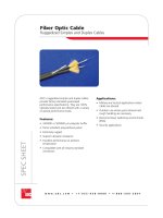
Patch Cords
Fiber Optic Patch Cords
Singlemode Patch Cord
Singlemode
Catalog Number
__ __ - __ - S - __ M
Cable Option
Connector Type**
Length
X Length in meters
FPC Connector on both ends (patch cord)
FPT Connector on one end (pigtail)
Cable Type
3 mm single
M 2 mm single
F 1.7 mm single
9 900 micron
Z 3 mm dual zip
2 2 mm dual zip
T 1.7 mm dual zip
Leave
Blank
*Requires 900 micron, 1.7 or 2 mm cable.
**For hybrid patch cords, enter both connector types in this field, separate them with a
slash mark and remove the “S” from the second connector.
Ordering Example
FPC2-SPFC-10M: Patch cord with ultra polish FC connectors on both ends, 2 mm dual zip
cable, 10 meters in length with standard breakout length of 12" on both ends.
SPSC SC ultra polish
SPFC FC ultra polish
SPLX LX.5
®
ultra polish*
SDLX LX.5
®
ultra polish duplex*
APSC SC angled polish
APFC FC angled polish
ALX5 LX.5
®
angled polish*
ADLX LX.5
®
angled polish duplex*
SPLC LC ultra polish*
Other connector types are available. Please contact ADC.
www.adc.com • +1-952-938-8080 • 1-800-366-3891
211
6/04 • 1247379
MSO Market Solutions
Buffered Fiber
900 micron
PVC Jacket
0.64 mm thick
Patch Cords
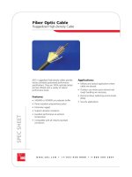
Multifiber Patch Cords (4 to 24 fibers)
Singlemode
Standard wall: Available with 4, 6, 12 or 32 tight buffered 1.7 mm fibers enclosed in a standard wall
outer jacket. Each 1.7 mm fiber is coded for easy identification of individual fibers. Central strength
member, aramid yarn; PVC jacket thickness 0.89 mm.
Soft wall: Available with 6, 8 or 12 tight buffered 900 micron fibers with a thin outer jacket. No central
strength member or aramid yarn; PVC jacket thickness 0.64 mm.
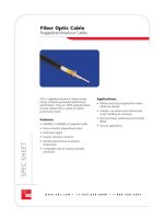
Thick wall: Available with 4 or 24 tight buffered 1.7 mm fibers. Each 1.7 mm fiber is coded for easy
identification of individual fibers. Central strength member, aramid yarn; PVC jacket thickness 1.65 mm.
Thin wall: Available with 4 tight buffered 900 micron fibers with a thin outer jacket (4.8 mm overall
diameter). No central strength member, aramid yarn; PVC jacket thickness 0.48 mm.
Ordering Examples
FPM-07/0-P005M: Multifiber patch cord with ultra polish SC connectors on one end, no connectors on the other
end (pigtail), 6-fiber soft wall, 5 meters long with standard breakout.
Standard Wall
(4-Fiber Shown)
Soft Wall
(12-Fiber Shown)
Thin Wall
(4-Fiber Shown)
Thick Wall
(4-Fiber Shown)
Catalog Number
FPM-0 __ / __ - __ __ __ __ M- __ __ / __ __
Connector Type
(1st and 2nd end)
Length
X Length in meters
Breakout Length
X Length in inches
Leave blank if both ends 12"
0 Stub
7 SC ultra polish
2 FC ultra polish
N LX.5
®
ultra polish
K LC ultra polish
E SC angled polish
D FC angled polish
Cable Type
D 4-fiber standard wall with 1.7 mm subunits
E 6-fiber standard wall with 1.7 mm subunits
P 6-fiber soft wall
L 8-fiber soft wall
F 12-fiber standard wall with 1.7 mm subunits
M 12-fiber soft wall
AD 24-fiber thick wall with 1.7 mm subunits
BD 32-fiber thick wall with 1.7 mm subunits
Aramid Yarn
Buffered Fiber
900 micron
Cable Jacket
0.48 mm thick
Cable Jacket, PVC
1.65 mm thick
Central Strength
Member
1.7 mm
Fiber subunit
Ripcord
Ripcord
Aramid Yarn
Cable Jacket, PVC
0.89 mm thick
Central Strength
Member
1.7 mm
Fiber subunit
Ripcord
Ripcord
Aramid Yarn
Other connector types are available. Please contact ADC.
www.adc.com • +1-952-938-8080 • 1-800-366-3891
212
6/04 • 1247379
MSO Market Solutions
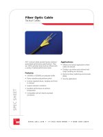
Patch Cords
TracerLight
™
Connector Identification System
ADC‘s innovative TracerLight
™
Connector Identification System offers a quick and accurate method of
identifying the termination point of optical patch cords. Each end of a TracerLight patch cord features a
flashing light source allowing technicians to visually trace individual patch cords from one end to the other
without pulling or affecting the patch cord.
TracerLight optical patch cords feature a flashing light source (LED) component near each connector
end. The TracerLight power source is inserted with minimal force into the TracerLight component on
one end of the patch cord. This causes the LED on each end to begin flashing rapidly. As a result, the
distant end of the patch cord can be quickly and easily identified without interruption of service.
Available in any standard length or connector style, TracerLight patch cords have the same functions,
features, and stringent environmental requirements as our standard patch cords. Optical performance of
the patch cords is not affected by the TracerLight components. TracerLight patch cords are installed in the
same manner as standard patch cords and can be pulled through ADC‘s FiberGuide
®
Fiber Cable
Management System with ease.
The compact power source is comprised of a
lightweight, plastic flashlight body featuring two
AA batteries and a printed circuit board (PCB). It
provides approximately 80 hours of continuous
service and features 1-hour auto-off. The end of
battery life is indicated by a slowing of the
blink rate.
TracerLight Power Source
FTL-PS
www.adc.com • +1-952-938-8080 • 1-800-366-3891
213
6/04 • 1247379
MSO Market Solutions
Patch Cords
TracerLight
™
Connector Identification System
FTL-2/2-D003M: Single fiber patch cord
with FC connectors on both ends,
3 meters in length
Ordering Example
Cable Type
D Singlemode single fiber
Example: 050 = 50 meters
125 = 125 meters
Catalog Number
FTL- __ / __ - __ __ __ __ M
Length (in meters)
Connector Style (first end)
7 SC ultra polish
2 FC ultra polish
N LX.5
®
ultra polish
E SC angled polish
D FC angled polish
L LX.5
®
angled polish
Connector Style (second end)
7 SC ultra polish
2 FC ultra polish
N LX.5
®
ultra polish
E SC angled polish
D FC angled polish
L LX.5
®
angled polish
Singlemode Ordering Information
Other connector types are available. Please contact ADC.
www.adc.com • +1-952-938-8080 • 1-800-366-3891
214
6/04 • 1247379
MSO Market Solutions
Other connector types are available. Please contact ADC.
ADC offers adjustable attenuation fiber patch
cords as a flexible, cost-effective solution to fixed
attenuated adapters. You can set your receiver
signal to the exact level desired, eliminating the
need to purchase a wide range of attenuators.
The attenuation level can be continuously adjusted
from 1.5 dB to 20 dB.
Patch Cords
Adjustable Optical Attenuation Patch Cord
Outside
Plant
Cables
Tx
Rx
Fiber Distribution Frame FOT Terminal
Attenuated
Equipment
Jumper
Attenuated patch cords used as equipment
jumpers may be purchased double ended or
single ended. With a single ended cord, the
stub end can be cut to the exact length and
field terminated with a connector. The
attenuator resides close to the fiber optic
terminal for easy access.
.5 m
Total Length
3 mm outer diameter
Connector #1*
(Closest connector to variable attenuator)
Connector #2
Catalog Number
APC- __ / __ - __ - __ M
Length in Meters
Example: 4 = 4 meters
35 = 35 meters
Connector #1*
SPSC SC ultra polish
SPFC FC ultra polish
APSC SC angled polish
APFC FC angled polish
Connector #2
Stub
PSC SC ultra polish
PFC FC ultra polish
APSC SC angled polish
APFC FC angled polish
Attenuation Range
S 4 to 20 dB**
H 1.5 to 20 dB**
Leave
Blank
**1310 nm wavelength
www.adc.com • +1-952-938-8080 • 1-800-366-3891
215
6/04 • 1247379
MSO Market Solutions
Cable Assemblies
IFC Assemblies
Coating
Cladding
Core
1 2 3 4 5 6 7 8 9 10 11 12
1 - Blue
2 - Orange
3 - Green
7 - Red
8 - Black
9 - Yellow
PVC INNER
JACKET
PVC OUTER
JACKET
FIBERGLASS
STRENGTH
MEMBERS
MYLAR
TAPE
RIBBON
AIR CORE
DETAIL B
SEE
DETAIL A
DETAIL A
SEE DETAIL B
4 - Brown
5 - Slate
6 - White
10 - Violet
11 - Rose
12 - Aqua
Ribbon IFC
Ribbon cable consists of multifibers arranged in ribbons. Each ribbon contains 12 fibers and is identified
as a subunit. The fibers which comprise the ribbons are color-coded for identification. With the
construction of ribbon cable, the fibers are located in the center of the cable and the outer jacket
provides the strength and protection of the cable. Three benefits are derived from the construction: the
outer jacket is more robust than stranded cable; the outer diameter of the cable remains constant over
the range of fiber counts available; and ribbon cable may be used with mass fusion type splicing.
ARAMID YARN
BUFFERED
FIBER
RIPCORD (2)
6 FIBER SUBUNIT
(SEE DETAIL A)
MYLAR
TAPE
COATING
CLADDING
CORE
BUFFERED FIBER
BUFFER
PVC CABLE
JACKET
CENTRAL
STRENGTH
MEMBERS
DETAIL A
BUFFERED
FIBER
RIPCORD (2)
12 FIBER SUBUNIT
(SEE DETAIL B)
MYLAR
TAPE
PVC CABLE
JACKET
CENTRAL
STRENGTH
MEMBERS
ARAMID YARN
PVC JACKET
DETAIL B
SEE
DETAIL C
SEE
DETAIL C
DETAIL C
PVC JACKET
1 BLUE
2 ORANGE
3 GREEN
4 BROWN
5 SLATE
6 WHITE
7 RED
8 BLACK
9 YELLOW
10 VIOLET
11 ROSE
12 AQUA
COLOR CODE CHART
6 fiber subunits
(example shows 36 fibers)
12 fiber subunits
(example shows 72 fibers)
(12 fiber shown)
PVC JACKET
BUFFERED FIBER
900 MICRON
ARAMID YARN
With stranded cable, individual 900 micron fibers make up the construction of the cable. The fibers are
bundled into subunits of 6 or 12 fibers each. Each subunit is identified and the individual fibers within
the subunits are color-coded. Stranded IFC diameters increase in proportion with the fiber counts.
www.adc.com • +1-952-938-8080 • 1-800-366-3891
216
6/04 • 1247379
MSO Market Solutions
Cable Assemblies
Singlemode IFC Assemblies
* For 144 or 216 fiber counts, additional fiber types and ordering information, contact your ADC representative.
** ADC will customize the breakout length of the IFC to ensure proper cable management. For competitors’
products, ADC recommends using the FCM breakout length (6' = 1.8 m).
For information on ADC’s FL2 panel products and Next Generation Frame Fiber Termination Blocks (FTB), call ADC
Technical Assistance Center, 1-800-366-3891.
Catalog Number
IFC - __ /__ __ __ __ __ - __
Length (In meters)
Example: 020 = 50 meters
150 = 150 meters
Connector Style
0 Stub
7 SC ultra polish
2 FC ultra polish
N LX.5
®
ultra polish
E SC angled polish
D FC angled polish
L LX.5
®
angled polish
K LC ultra polish
Cable Type*
A 12-fiber stranded
B 24-fiber stranded
C 36-fiber stranded
2 48-fiber stranded
V 72-fiber stranded
L 96-fiber stranded
NA 12-fiber ribbon
HA 24-fiber ribbon
MA 36-fiber ribbon
JA 48-fiber ribbon
DS 72-fiber ribbon
LA 96-fiber ribbon
Breakout/Panel Type**
8" FCM
L FDM
2A FL2, 12 exit up or down
2B FL2, 24 exit up or down
2C FL2, 48 exit up or down
2D FL2, 72 exit up
2E FL2, 96 exit up
2F FL2, 72 exit down
2G FL2, 96 exit down
FTB FTB MOD
3A1 FL1-A, bottom
3A2 FL1-A, top
LEAVE
BLANK
www.adc.com • +1-952-938-8080 • 1-800-366-3891
217
6/04 • 1247379
MSO Market Solutions
Attenuators
In-Line Attenuators
ADC’s in-line attenuators are installed between an
adapter and a connector; they are fused attenuators,
providing exceptional optical performance.
Description
SC Ultra
05 dB
10 dB
15 dB
20 dB
SC Angled
05 dB
10 dB
15 dB
20 dB
FC Ultra
05 dB
10 dB
15 dB
20 dB
FC Angled
05 dB
10 dB
15 dB
20 dB
LX.5
®
Ultra
03 dB
05 dB
07 dB
10 dB
12 dB
15 dB
20 dB
LX.5
®
Angled
03 dB
05 dB
07 dB
10 dB
12 dB
15 dB
20 dB
LC Ultra
5
10
15
20
Catalog Number
FOA-INSC05
FOA-INSC10
FOA-INSC15
FOA-INSC20
FOA-INASC05
FOA-INASC10
FOA-INASC15
FOA-INASC20
FOA-INFC05
FOA-INFC10
FOA-INFC15
FOA-INFC20
FOA-INAFC05
FOA-INAFC10
FOA-INAFC15
FOA-INAFC20
FOA-INLX03
FOA-INLX05
FOA-INLX07
FOA-INLX10
FOA-INLX12
FOA-INLX15
FOA-INLX20
FOA-INALX03
FOA-INALX05
FOA-INALX07
FOA-INALX10
FOA-INALX12
FOA-INALX15
FOA-INALX20
FOA-INLC05
FOA-INLC10
FOA-INLC15
FOA-INLC20
Ordering Information
In-Line SC Attenuator
Adapter
In-Line
Attenuator
Connector/ Patch Cord
SPECIFICATIONS
Attenuation Tolerance
≤5 dB ±0.75 dB
>5 dB ±10%
218
6/04 • 1247379
MSO Market Solutions
www.adc.com • +1-952-938-8080 • 1-800-366-3891
218
Accessories
The fiber connector/adapter cleaning kit contains
all the items required to adequately clean fiber
connectors and adapters. The performance of an
optical fiber system is largely dependent on the
fiber connector cleaning procedures followed
prior to installation. It is suggested that all the
connectors and adapters be cleaned before
making any connections. The kit cleans
approximately 500 connectors or adapters.
Description
Fiber connector/adapter cleaning kit
Includes:
• Instruction sheet
• Lint-free wipes
• Isopropyl alcohol
• Cotton swabs
• Lint-free pipe cleaners
• Oil-free compressed air
Catalog Number
FPC-CLNKIT
Ordering Information
Fiber Connector/Adapter Cleaning Kit
This kit contains flammable alcohol and compressed air. For this reason, it can be shipped
by surface method only.
219
6/04 • 1247379
MSO Market Solutions
www.adc.com • +1-952-938-8080 • 1-800-366-3891
219
Fiber Optic Specifications
Patch Cords
L
Length Tolerance
0 to 15 m +16 cm/-0 cm
+15 m +1%/-0 cm
Length Tolerance
0 to 15 m +16 cm/-0 cm
+15 m +1%/-0 cm
Stranded
Length Tolerance
0 to 15 m +16 cm/-0 cm
+15 m +1%/-0 cm
Ribbon
Length Tolerance
0 to 20 m +15 cm/-0 cm
+20 m +90 cm/-0 cm
Multifiber
L
IFC
L
SC ST
®
FC LC LX.5
®
0.2 dB max. 0.2 dB max. 0.2 dB max. 0.3 dB max. 0.2 dB max.
0.09 dB typical 0.15 dB typical 0.09 dB typical 0.1 dB typical 0.08 dB typical
57 dB min. 57 dB min. 57 dB min. 55 dB min. 57 dB min.
± 50 nm ± 50 nm ± 50 nm -100 to +50 nm ± 50 nm
50 micron max. 50 micron max. 50 micron max. 50 micron max. 50 micron max.
10-25 mm 10-25 mm 10-25 mm 10-25 mm 10-25 mm
SC ST
®
FC LX.5
®
E-2000
0.5 dB max. 0.5 dB max. 0.5 dB max. 0.2 dB max. 0.5 dB max.
0.15 dB typical 0.2 dB typical 0.15 dB typical 0.08 dB typical 0.2 dB typical
65 dB min. 65 dB min. 65 dB min. 65 dB min. 65 dB min.
5 - 15 mm 5 - 15 mm 5 - 15 mm 5 - 12 mm 5 - 15 mm
-100 to +50 nm -100 to +50 nm -100 to +50 nm ± 50 nm -100 to +50 nm
50 micron 50 micron 50 micron 65 micron 50 micron
8˚ ± 0.5 8˚ ± 0.5 8˚ ± 0.5 8˚ ±0.5 8˚ ± 0.5
SC ST
®
FC LX.5
®
0.7 dB max. 0.7 dB max. 0.7 dB max. 0.4 dB max.
0.15 dB typical
20 dB min. 20 dB min. 20 dB min. 25 dB min.
Singlemode Ultra
Polish Connectors (UPC)
Insertion Loss
(1310 and 1550 nm)
Return Loss
(1310 and 1550 nm)
Fiber Recess
Apex Offset
Radius of Curvature
Singlemode Angled
Polish Connectors (APC)
Insertion Loss
(1310 and 1550 nm)
Return Loss
(1310 and 1550 nm)
Polished Endface Radius
Fiber Recess
Apex Offset
Endface Angle
Multimode Ultra
Polish Connectors
Insertion Loss
(1310 nm)
Return Loss
(1310 nm)