Tài liệu Configuring Distance Vector Protocols docx
Bạn đang xem bản rút gọn của tài liệu. Xem và tải ngay bản đầy đủ của tài liệu tại đây (423.52 KB, 32 trang )
Color profile: Generic CMYK printer profile
CertPrs8
Composite Default screen
/ CCNA Cisco Certified Network Associate Study Guide / Deal / 222934-9 / Chapter 10
Blind Folio 10:1
10
Configuring
Distance Vector
Protocols
CERTIFICATION OBJECTIVES
10.01
IP Routing Protocol Basics
✓
Two-Minute Drill
10.02
IP RIP
Q&A
Self Test
10.03
IP IGRP
D:\omh\CertPrs8\934-9\ch10.vp
Monday, August 04, 2003 12:13:16 PM
Color profile: Generic CMYK printer profile
CertPrs8 /
Composite Default screen
2
Chapter 10:
CCNA Cisco Certified Network Associate Study Guide / Deal / 222934-9 / Chapter 10
Configuring Distance Vector Protocols
I
n the preceding chapter, you gained an overview of routing protocols, including the
different types and their advantages and disadvantages. This chapter covers the basic
configuration of distance vector protocols, specifically the IP Routing Information
Protocol (RIP) and the Interior Gateway Routing Protocol (IGRP). It focuses on the basics
of these protocols; advanced configuration of these protocols is beyond the scope of this book.
However, by the end of the chapter, you’ll be able to configure routers running RIP and IGRP
that will route traffic in a network.
CERTIFICATION OBJECTIVE 10.01
IP Routing Protocol Basics
Before learning about how to configure RIP and IGRP, consider some basic configuration
tasks that are required no matter what routing protocol you are running. You need to
perform two basic steps when setting up IP routing on your router:
■ Enable the routing protocol.
■ Assign IP addresses to your router’s interfaces.
Memorize the two basic
steps for setting up IP routing.
Please note that the order of these tasks is not
important. You already know how to configure
an IP address on the router’s interface: this was
discussed in Chapter 5. The following sections
cover the first bullet point in more depth.
The router Command
Enabling an IP routing protocol is a two-step process. First, you must go into Router
Subconfiguration mode. This mode determines the routing protocol that you’ll be
running. Within this mode, you’ll configure the characteristics of the routing protocol.
To enter the routing protocol’s configuration mode, use the following command:
Router(config)# router name_of_the_IP_routing_protocol
Router(config-router)#
The router command is used to access the routing protocol that you wish to
configure; it doesn’t enable it. If you are not sure of the name of the routing protocol
that you wish to enable, use the context-sensitive help feature:
D:\omh\CertPrs8\934-9\ch10.vp
Monday, August 04, 2003 12:13:16 PM
Color profile: Generic CMYK printer profile
CertPrs8
Composite Default screen
/ CCNA Cisco Certified Network Associate Study Guide / Deal / 222934-9 / Chapter 10
IP Routing Protocol Basics
3
Router(config)# router ?
bgp
Border Gateway Protocol (BGP)
egp
Exterior Gateway Protocol (EGP)
eigrp
Enhanced Interior Gateway Routing
Protocol (EIGRP)
igrp
Interior Gateway Routing Protocol (IGRP)
isis
ISO IS-IS
iso-igrp
IGRP for OSI networks
mobile
Mobile routes
odr
On Demand stub Routes
ospf
Open Shortest Path First (OSPF)
rip
Routing Information Protocol (RIP)
static
Static routes
traffic-engineering Traffic engineered routes
Router(config)#
As you can see from the context-sensitive help output, you have a lot of IP routing
protocols at your disposal. One important item to point out is that the router
command doesn’t turn on the routing protocol. This process is done in the protocol’s
Router Subconfiguration mode, indicated by the (config-router) prompt.
The network Command
Once in the routing protocol, you need to specify what interfaces are to participate in
the routing process. By default, no interfaces participate. To specify which interfaces
will participate, use the network Router Subconfiguration mode command:
Router(config-router)# network IP_network_#
As soon as you enter a network number, the routing process is active. For distance
vector protocols like RIP and IGRP, you need to enter only the class A, B, or C network
number or numbers that are associated with your interface. In other words, if you
have subnetted 192.168.1.0 with a subnet mask of 255.255.255.192 (/26), and you have
subnets 192.168.1.0/26, 192.168.1.64/26, 192.168.1.128/26, and 192.168.1.192/26, you
don’t need to enter each specific subnet. Instead, just enter 192.168.1.0, and this will
accommodate all interfaces that are associated with this class C network. If you specify
a subnet, the router will convert it to the class address, because RIP and IGRP are classful
protocols.
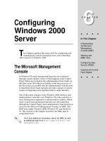
Let’s take a look at a simple example to show the configuration, shown in Figure 10-1.
In this example, I’ll focus on the configuration of the network commands, assuming
that the routing protocol is a classful protocol, such as RIP or IGRP. In this example,
the router is connected to a Class B network (172.16.0.0) and a Class C network
(192.168.1.0), both of which are subnetted.
D:\omh\CertPrs8\934-9\ch10.vp
Monday, August 04, 2003 12:13:16 PM
Color profile: Generic CMYK printer profile
CertPrs8 /
Composite Default screen
4
Chapter 10:
CCNA Cisco Certified Network Associate Study Guide / Deal / 222934-9 / Chapter 10
Configuring Distance Vector Protocols
FIGURE 10-1
Simple network
example
Let’s assume that you forgot that you need to enter only the classful network
numbers, and that you entered the subnetted values instead, like this:
Router(config-router)#
Router(config-router)#
Router(config-router)#
Router(config-router)#
network
network
network
network
172.16.1.0
172.16.2.0
192.168.1.64
192.168.1.128
When entering your network statements, you need to include any network that
is associated with your router’s interfaces; if you omit a network, then your router will
not include the omitted interface in the routing process. As you can see from the
preceding example, all of the subnets were included. Remember, however, that the
router requires only that you enter the class addresses. If you were to execute a show
running-config command, you would not see the four networks just listed, but
just the Class B and C network numbers. You shouldn’t worry about this; it’s just that
you entered more commands than were necessary. In reality, you needed to enter only
two network commands:
Router(config-router)# network 172.16.0.0
Router(config-router)# network 192.168.1.0
For exam purposes,
I would recommend that you enter the
class networks instead of the subnets
on the simulator questions. Remember
D:\omh\CertPrs8\934-9\ch10.vp
Monday, August 04, 2003 12:13:16 PM
that the simulator is just that—a simulator.
It’s not a full-functioning IOS router. You’ll
need to be very familiar with the router
and network commands.
Color profile: Generic CMYK printer profile
CertPrs8
Composite Default screen
/ CCNA Cisco Certified Network Associate Study Guide / Deal / 222934-9 / Chapter 10
IP RIP
5
Both ways of entering your statements is correct, but the latter is what the router
will use if you type in all of the specific subnets.
10.01. The CD contains a multimedia demonstration of an introduction to
basic IP routing protocol configuration.
CERTIFICATION OBJECTIVE 10.02
IP RIP
IP RIP (Routing Information Protocol) comes in two different versions: 1 and 2.
Version 1 is a distance vector protocol and is defined in RFC 1058. Version 2 is a
hybrid protocol and is defined in RFCs 1721 and 1722. The CCNA exam focuses on
version 1. However, you still need to know a few things about RIPv2, specifically its
characteristics. This section covers the basics of configuring and troubleshooting your
network using IP RIP.
Characteristics of RIPv1 and RIPv2
As you recall from the last chapter, RIP is a distance vector protocol. RIP is a very old
protocol and therefore is very stable; in other words, Cisco really doesn’t do that much
development on the protocol, unlike other, more advanced protocols. Therefore,
you can feel very safe that when you upgrade your IOS to a newer version, RIP will
function the same way that it did in the previous release. This section includes brief
overviews of both versions of RIP.
RIPv1
RIPv1 uses local broadcasts to share routing information. These updates are periodic in
nature, occurring, by default, every 30 seconds, with a hold-down period of 180 seconds.
Both versions of RIP use hop count as a metric, which is not always the best metric to use.
For instance, if you had two paths to reach a network, where one was a two-hop Ethernet
connection, and the other was a one-hop 64 Kbps WAN connection, RIP would use the
slower 64 Kbps connection because it has a lesser hop count value. You have to remember
this little tidbit when looking at how RIP will populate your router’s routing table. To
prevent packets from circling around a loop forever, both versions of RIP solve counting
to infinity by placing a hop count limit of 15 hops on packets. Any packet that reaches
the sixteenth hop will be dropped.
D:\omh\CertPrs8\934-9\ch10.vp
Monday, August 04, 2003 12:13:16 PM
Color profile: Generic CMYK printer profile
CertPrs8 /
Composite Default screen
6
Chapter 10:
CCNA Cisco Certified Network Associate Study Guide / Deal / 222934-9 / Chapter 10
Configuring Distance Vector Protocols
And as I mentioned in the last section, RIPv1 is a classful protocol. This is important
for configuring RIP and subnetting your IP addressing scheme: you can use only one
subnet mask value for a given Class A, B, or C network. For instance, if you have a Class
B network such as 172.16.0.0, you can subnet it with only one mask. As an example,
you couldn’t use 255.255.255.0 and 255.255.255.128 on 172.16.0.0—you can choose
only one.
Another interesting feature is that RIP supports up to six equal-cost paths to
a single destination, where all six paths can be placed in the routing table and
the router can load-balance across them. The
default is actually four paths, but this can be
increased up to a maximum of six. Remember
IP RIPv1, a classful
that an equal-cost path is where the hop count
protocol, broadcasts updates every 30
value is the same. RIP will not load-balance
seconds, and has a hold-down period
across unequal-cost paths.
of 180 seconds. Hop count is used as
Let’s look at Figure 10-2 to illustrate equala metric.
cost-path load balancing. In this example,
RouterA has two equal-cost paths to 10.0.0.0
(with a hop count of 1) via RouterB and RouterC. There are actually two advantages
of putting both of these paths in RouterA’s routing table:
■ First, the router can perform load balancing to 10.0.0.0, taking advantage of
the bandwidth on both of these links.
■ And second, convergence is sped up if one of the paths fails. For example, if
the connection between RouterA and RouterB fails, RouterA can still access
network 10.0.0.0 via RouterB and has this information in its routing table;
therefore, convergence is instantaneous.
For these two reasons, many routing protocols support parallel paths to a single
destination. Some protocols, such as IGRP and EIGRP, even support unequal-cost
load balancing, which is discussed in the section "IGRP" of this chapter.
RIPv2
One thing you have to keep in the back of your mind when dealing with RIPv2
is that it is based on RIPv1 and is, at heart, a distance vector protocol with routing
enhancements built into it. Therefore, it is commonly called a hybrid protocol. I
pointed out some of the characteristics that both versions of RIP have in common
in the preceding section. This section focuses on the characteristics unique to RIPv2.
One major enhancement to RIPv2 pertains to how it deals with routing updates.
Instead of using broadcasts, RIPv2 uses multicasts. And to speed up convergence,
D:\omh\CertPrs8\934-9\ch10.vp
Monday, August 04, 2003 12:13:16 PM
Color profile: Generic CMYK printer profile
CertPrs8
Composite Default screen
/ CCNA Cisco Certified Network Associate Study Guide / Deal / 222934-9 / Chapter 10
IP RIP
7
FIGURE 10-2
Equal-cost load
balancing
RIPv2 supports triggered updates—when a change occurs, a RIPv2 router will
immediately propagate its routing information to its connected neighbors.
A second major enhancement that RIPv2 has is that it is a classless protocol. RIPv2
supports variable-length subnet masking (VLSM), which allows you to use more than
one subnet mask for a given class network number. VLSM allows you to maximize
the efficiency of your addressing design as well as to summarize routing information
to create very large, scalable networks. VLSM is discussed in Chapter 12.
As a third enhancement, RIPv2 supports authentication. You can restrict what
routers you want to participate in RIPv2. This is accomplished using a hashed
password value.
Even with all of these advanced characteristics, RIPv2 is still, at heart, a distance
vector protocol. It uses hop count as a metric, supports the same solutions to solve
routing loop problems, has a 15-hop count limit, and shares other characteristics of
these protocols.
RIPv2 is a hybrid
protocol, based on RIPv1. It uses
multicasts to disseminate routing
information and supports triggered
D:\omh\CertPrs8\934-9\ch10.vp
Monday, August 04, 2003 12:13:17 PM
updates. Unlike RIPv1, RIPv2 supports
VLSM, which allows you to summarize
routing information. Otherwise, its
characteristics are like RIPv1.
Color profile: Generic CMYK printer profile
CertPrs8 /
Composite Default screen
8
Chapter 10:
CCNA Cisco Certified Network Associate Study Guide / Deal / 222934-9 / Chapter 10
Configuring Distance Vector Protocols
Configuring IP RIP
As you will see in this section, configuring RIP is a very easy and straightforward
process. The basic configuration of RIP involves the following two commands:
Router(config)# router rip
Router(config-router)# network IP_network_#
Use the router rip
and network commands to configure RIP
routing. Remember to put in the class
address (not the subnetted network
number) in the network statement.
As explained in the preceding section, RIPv1 is
classful and RIPv2 is classless. However, whenever
you configure either version of RIP, the network
command assumes classful: You need to enter only
the Class A, B, or C network number, not the
subnets, as was discussed earlier in this chapter.
If you refer back to Figure 10-1, the router’s RIPv1
configuration would look like this:
Router(config)# router rip
Router(config-router)# network 172.16.0.0
Router(config-router)# network 192.168.1.0
10.02. The CD contains a multimedia demonstration of a basic RIP
configuration on a router.
Specifying RIP Version 1 and 2
By default, the IOS accepts both RIPv1 and RIPv2 routing updates; however, it generates
only RIPv1 updates. You can configure your router to
■ Accept and send RIPv1 only
■ Accept and send RIPv2 only
■ Use a combination of the two, depending on your interface configuration
To accomplish either of the first two items in the list, you need to set the version
in your RIP configuration:
Router(config)# router rip
Router(config-router)# version 1|2
When you specify the appropriate version number, your RIP routing process will
send and receive only the version packet type that you configured.
You can also control which version of RIP is running on an interface-by-interface
basis. For instance, you might have a bunch of new routers at your site that support
D:\omh\CertPrs8\934-9\ch10.vp
Monday, August 04, 2003 12:13:17 PM
Color profile: Generic CMYK printer profile
CertPrs8
Composite Default screen
/ CCNA Cisco Certified Network Associate Study Guide / Deal / 222934-9 / Chapter 10
IP RIP
9
both versions and a remote office that understands only RIPv1. In this situation, you
can configure your routers to generate RIPv2 updates on all their LAN interfaces, but
for the remote access connection at the corporate site, you could set the interface to
run only RIPv1.
To control which version of RIP should handle generating updates on an interface,
use the following configuration:
Router(config)# interface type [slot_#/]port_#
Router(config-router)# ip rip send version 1 | version 2 |
version 1 2
A Cisco router running
RIP, by default, generates only RIPv1
updates but processes received v1 and
v2 updates. Use the version command
to change the RIP version.
With the ip rip send command, you can
control which version of RIP the router should
use on the specified interface when generating
RIP updates. You can be specific by specifying
version 1 or 2, or you can specify both.
To control what version of RIP should be
used when receiving RIP updates, use the
following configuration:
Router(config)# interface type [slot_#/]port_#
Router(config-router)# ip rip receive version 1 | version 2 |
version 1 2
10.03. The CD contains a multimedia demonstration of RIPv2 configuration
on a router.
Configuration Example
Let’s use a simple network example, shown in Figure 10-3, to illustrate configuring
RIPv1.Here’s RouterA’s configuration:
RouterA(config)# router rip
RouterA(config-router)# network 192.168.1.0
RouterA(config-router)# network 192.168.2.0
Here’s RouterB’s configuration:
RouterB(config)# router rip
RouterB(config-router)# network 192.168.2.0
RouterB(config-router)# network 192.168.3.0
As you can see, to configure RIP is very easy.
D:\omh\CertPrs8\934-9\ch10.vp
Monday, August 04, 2003 12:13:17 PM
Color profile: Generic CMYK printer profile
CertPrs8 /
Composite Default screen
10
Chapter 10:
CCNA Cisco Certified Network Associate Study Guide / Deal / 222934-9 / Chapter 10
Configuring Distance Vector Protocols
FIGURE 10-3
RIPv1
configuration
example
Troubleshooting IP RIP
Once you have configured IP RIP, you have a variety of commands available to view
and troubleshoot your configuration and operation of RIP:
■ show ip protocols
■ show ip route
■ debug ip rip
The following sections cover these commands in more depth.
One other important command to point out is the clear ip route * Privilege
EXEC mode command. This command clears and rebuilds the IP routing table. Any
time that you make a change to a routing protocol, you should clear and rebuild the
routing table with this command. You can replace the “*” with a specific network
number, if you choose to do so--this will only clear the specified route from the routing
table. Please note that the clear command only clears dynamic routes: static and
connected routes cannot be cleared from the routing table with this command.
The show ip protocols Command
The show ip protocols command displays all of the IP routing protocols that you
have configured and are running on your router. Here’s an example of this command:
Router# show ip protocols
Routing Protocol is "rip"
Sending updates every 30 seconds, next due in 5 seconds
Invalid after 180 seconds, hold down 180, flushed after 240
Outgoing update filter list for all interfaces is not set
Incoming update filter list for all interfaces is not set
Redistributing: rip
Default version control: send version 1, receive any version
Interface
Send Recv
Key-chain
Ethernet0
1
1 2
Ethernet1
1
1 2
D:\omh\CertPrs8\934-9\ch10.vp
Monday, August 04, 2003 12:13:17 PM
Color profile: Generic CMYK printer profile
CertPrs8
Composite Default screen
/ CCNA Cisco Certified Network Associate Study Guide / Deal / 222934-9 / Chapter 10
IP RIP
Routing for Networks:
192.168.1.0
192.168.2.0
Routing Information Sources:
Gateway
Distance
192.168.2.2
120
Distance: (default is 120)
11
Last Update
00:00:22
In this example, RIP is running on the router.
The routing update interval is 30 seconds, with
the next update being sent in 5 seconds. You
can see that two interfaces are participating:
RIP advertises routes
ethernet0 and ethernet1. On these
every 30 seconds. Its hold-down period
interfaces, RIPv1 is being used to generate
is 180 seconds, and its flush period is 240
updates and both versions are accepted if they
seconds. Know the output of the show
are received on these two interfaces. You can see
ip protocols command.
the two networks specified with the network
commands: 192.168.1.0 and 192.168.2.0. In this example, this router received an
update 22 seconds ago from a neighboring router: 192.168.2.2. And last, the default
administrative distance of RIP is 120.
10.04. The CD contains a multimedia demonstration of the show ip
protocols command for RIP on a router.
The show ip route Command
Your router keeps a list of the best paths to destinations in a routing table. There is
a separate routing table for each routed protocol. For instance, if you are running IP
and IPX, your router will have two routing tables: one for each. However, if you are
running two routing protocols for a single routed protocol, such as IP RIPv1 and IGRP,
your router will have only one routing table for IP.
To view the routing table, use the show ip route command:
Router# show ip route
Codes: C - connected, S - static, I - IGRP, R - RIP,
M - mobile, B - BGP, D - EIGRP, EX - EIGRP external,
O - OSPF, IA - OSPF inter area, N1 - OSPF NSSA
external type 1, N2 - OSPF NSSA external type 2,
E1 - OSPF external type 1, E2 - OSPF external type 2,
E - EGP, i - IS-IS, L1 - IS-IS level-1,
L2 - IS-IS level-2, * - candidate default,
U - per-user static route, o - ODR,
T - traffic engineered route
D:\omh\CertPrs8\934-9\ch10.vp
Monday, August 04, 2003 12:13:17 PM
Color profile: Generic CMYK printer profile
CertPrs8 /
Composite Default screen
12
Chapter 10:
CCNA Cisco Certified Network Associate Study Guide / Deal / 222934-9 / Chapter 10
Configuring Distance Vector Protocols
Gateway of last resort is not set
172.16.0.0/24 is subnetted, 2 subnets
C
172.16.1.0 is directly connected, Ethernet0
R
172.16.2.0 [120/1] via 172.16.1.2, 00:00:21, Ethernet0
192.168.1.0/24 is subnetted, 2 subnets
C
192.168.1.0 is directly connected, Serial0
R
192.168.2.0/24 [120/2] via 192.168.1.2, 00:00:02, Serial2
In this example, you can see that there are
two types of routes in the routing table: R is for
RIP, and C is for a directly connected network.
For the RIP entries, you can see two numbers
Remember the output of
in brackets: the administrative distance of the
the show ip route command for the
route and the metric. For instance, 172.16.2.0
RIP routing protocol.
has an administrative distance of 120 and a hop
count of 1. Following this is the neighboring RIP router that advertised the route
(172.16.1.2), how long ago an update for this route was received from the neighbor
(21 seconds), and on which interface this update was learned (Ethernet0).
10.05. The CD contains a multimedia demonstration of the show ip route
command for RIP on a router.
The debug ip rip Command
Remember that the show commands show a static display of what the router knows
and sometimes don’t display enough information concerning a specific issue or problem.
For instance, you might be looking at your routing table with the show ip route
command and expect a certain RIP route to be appearing from a connected neighbor,
but this network is not being shown. Unfortunately, the show ip route command
won’t tell you why a route is or isn’t in the routing table. However, you can resort to
debug commands to assist you in your troubleshooting.
For more detailed troubleshooting of IP RIP problems, you can use the debug
ip rip command, shown here:
Router# debug ip rip
RIP protocol debugging is on
Router#
00:12:16: RIP: received v1 update from 192.168.1.2 on Serial0
00:12:16:
192.168.2.0 in 1 hops
00:12:25: RIP: sending v1 update to 255.255.255.255 via Ethernet0
172.16.1.1)
00:12:26:
network 192.168.1.0, metric 0
00:12:26:
network 192.168.2.0, metric 1
D:\omh\CertPrs8\934-9\ch10.vp
Monday, August 04, 2003 12:13:18 PM
Color profile: Generic CMYK printer profile
CertPrs8
Composite Default screen
/ CCNA Cisco Certified Network Associate Study Guide / Deal / 222934-9 / Chapter 10
IP RIP
13
This command displays the routing updates sent and received on the router’s
interfaces. In this code example, the router received an update from 192.168.1.2 on
Serial0. This update contained one network: 192.168.2.0. After this update, you
can see that your router generated a RIP update (local broadcast--255.255.255.255)
on its Ethernet0 interface. This update contains two networks: 192.168.1.0 and
192.168.2.0. Also notice the metrics associated with these routes: 192.168.1.0 is
connected to this router, while 192.168.2.0 is one hop away. When the neighboring
router connected to Ethernet0 receives this update, it will increment the hop
count by 1 for each route in the update.
When using debug commands, you must be at Privilege EXEC mode. To disable a
specific debug command, negate it with the no parameter. To turn off debugging for
all debug commands, use either the undebug all or no debug all command.
10.06. The CD contains a multimedia demonstration of the debug ip rip
command for RIP on a router.
Be familiar with the
output of the debug ip rip command
and how to disable debug: preface the
debug command with the no parameter or
use the undebug all or no debug all
command.
EXERCISE 10-1
ON THE CD
Configuring RIP
These last few sections dealt with configuring RIP on a router. This exercise will help
you reinforce this material for setting up and troubleshooting RIP. You’ll perform this lab
using Boson’s NetSim™ simulator. This exercise has you set IP RIP on the two routers
(2600 and 2500). You can find a picture of the network diagram for Boson’s NetSim™
simulator in the Introduction for this book. After starting the simulator, click on the
LabNavigator button. Next, double-click on Exercise 10-1 and click on the Load Lab
button. This will load the lab configuration based on Chapter 5’s and 7’s exercises.
1. On the 2600, verify that the fa0/0 and s0 interfaces are up. If not, bring
them up. Examine the IP addresses configured on the 2600 and look at its
routing table.
D:\omh\CertPrs8\934-9\ch10.vp
Monday, August 04, 2003 12:13:18 PM
Color profile: Generic CMYK printer profile
CertPrs8 /
Composite Default screen
14
Chapter 10:
CCNA Cisco Certified Network Associate Study Guide / Deal / 222934-9 / Chapter 10
Configuring Distance Vector Protocols
At the top of the simulator in the menu bar, click on the eRouters icon
and choose 2600. On the 2600, use the show interfaces command to
verify your configuration. If fa0/0 and s0 are not up, go into the interfaces
(fa0/0 and s0) and enable them: configure terminal, interface
type [slot_#/]port_#, no shutdown, and end. Use the show
interfaces command to verify that the IP addresses you configured
in Chapter 5 are still there. Use the show ip route command. You
should have two connected networks: 192.168.1.0 connected to fa0/0
and 192.168.2.0 connected to s0.
2. On the 2500, verify that the e0 and s0 interfaces are up. If not, bring them up.
Examine the IP addresses configured on the 2500 and look at its routing table.
At the top of the simulator in the menu bar, click on the eRouters icon and
choose 2500. On the 2500, Use the show interfaces command to verify
your configuration. If e0 and s0 are not up, go into the interfaces (e0 and s0)
and enable them: configure terminal, interface type port_#,
no shutdown, and end. Use the show interfaces command to verify
your configuration. Use the show interfaces command to verify that the
IP addresses you configured in Chapter 5 are still there. Use the show ip
route command. You should have two connected networks: 192.168.3.0
connected to e0 and 192.168.2.0 connected to s0.
3. Test connectivity between Host1 and the 2600. Test connectivity between
Host3 and the 2500. Test connectivity between Host3 and Host1.
At the top of the simulator in the menu bar, click on the eStations icon and
choose Host1. From Host1, ping the 2600 router (the default gateway): ping
192.168.1.1. The ping should be successful. At the top of the simulator in
the menu bar, click on the eStations icon and choose Host3. From the Host3,
ping the 2500 router (the default gateway): ping 192.168.3.1. The ping
should be successful. From the Host3, ping Host1: ping 192.168.1.10.
The ping should fail. Why? there is no route from the 2500 to this destination.
(Look at the 2500’s routing table: it doesn’t list 192.168.1.0/24.)
4. Access the 2500 and examine the routing table to see why the ping failed.
At the top of the simulator in the menu bar, click on the eRouters icon and
choose 2500. Examine the routing table: show ip route. Notice that it
doesn’t list 192.168.1.0/24, which explains why Host3 can’t reach Host1.
5. Enable RIP on the 2600 and 2500 routers.
At the top of the simulator in the menu bar, click on the eRouters icon and
choose 2600. On the 2600, execute the following: router rip, network
D:\omh\CertPrs8\934-9\ch10.vp
Monday, August 04, 2003 12:13:18 PM
Color profile: Generic CMYK printer profile
CertPrs8
Composite Default screen
/ CCNA Cisco Certified Network Associate Study Guide / Deal / 222934-9 / Chapter 10
IP RIP
15
192.168.1.0, and network 192.168.2.0. At the top of the simulator
in the menu bar, click on the eRouters icon and choose 2500. On the 2500,
execute the following: router rip, network 192.168.2.0, and
network 192.168.3.0.
6. On the 2600 and 2500, verify the operation of RIP.
At the top of the simulator in the menu bar, click on the eRouters icon and
choose 2600. Use the show ip protocols command to make sure that RIP
is configured—check for the neighboring router’s IP address. Use the show ip
route command and look for the remote LAN network number as a RIP (R)
entry in the routing table. On the 2600, you should see 192.168.3.0, which was
learned from the 2500. At the top of the simulator in the menu bar, click on the
eRouters icon and choose 2500. Use the show ip protocols command to
make sure that RIP is configured—check for the neighboring router’s IP address.
Use the show ip route command and look for the remote LAN network
number as a RIP (R) entry in the routing table. On the 2500, you should see
192.168.1.0, which was learned from the 2600.
7. On Host1, test connectivity to Host3.
At the top of the simulator in the menu bar, click on the eStations icon and
choose Host1. On Host1, test connectivity: ping 192.168.3.2. The
ping should be successful.
EXERCISE 10-2
ON THE CD
Basic RIP Troubleshooting
This section dealt with the basics of IP RIP. This is a troubleshooting exercise,similar to
Exercise 9-2. In that exercise, you were given a configuration task to set up RIP. In this
exercise, the network is already configured; however, there are three problems that you’ll
need to find and fix in order for the network to operate correctly. All of these problems
deal with IP (layer-3) connectivity. You’ll perform this exercise using Boson’s NetSim™
simulator. The addressing scheme is the same as that configured in Chapter 5. After
starting up the simulator, click on the LabNavigator button. Next, double-click on
Exercise 10-2 and click on the Load Lab button. This will load the lab configuration
based on Chapter 5’s exercises (with problems, of course).
Lets’ start with your problem: Host1 cannot ping Host3. Your task is to figure out
what the problems are (there are three) and fix them. In this example, RIPv1 has
D:\omh\CertPrs8\934-9\ch10.vp
Monday, August 04, 2003 12:13:18 PM
Color profile: Generic CMYK printer profile
CertPrs8 /
Composite Default screen
16
Chapter 10:
CCNA Cisco Certified Network Associate Study Guide / Deal / 222934-9 / Chapter 10
Configuring Distance Vector Protocols
been preconfigured on the routers. I recommend that you try this troubleshooting
process on your own first; if you havetrouble with it, come back to the steps and
solutions providedhere.
1. Test connectivity from Host1 to Host3 with ping as well as from Host1 to
its default gateway.
At the top of the simulator in the menu bar, click on the eStations icon and
choose Host1. On Host1, ping Host3: ping 192.168.3.2. Note that the
ping fails. Examine the IP configuration on Host1 by executing: winipcfg.
Make sure the IP addressing information is correct: IP address of 192.168.1.10,
subnet mask of 255.255.255.0, and default gateway address of 192.168.1.1.
Click on the Cancel button to close winipcfg. Ping the default gateway
address: ping 192.168.1.1. The ping should fail, indicating that at
least layer-3 is functioning between Host1 and the 2600.
2. Check the 2600’s IP configuration.
At the top of the simulator in the menu bar, click on the eRouters icon and
choose 2600. From the 2600, ping Host1: ping 192.168.1.10. The ping
should fail. Examine the interface on the 2600: show interface fa0/0.
The interface is enabled, but has an incorrect IP address: 192.168.1.254. Fix the
IP address: configure terminal, interface fa0/0, ip address
192.168.1.1 255.255.255.0, end. Verify the IP address: show
interface fa0/0. Retry the ping test: ping 192.168.1.10. The
ping should be successful. Save the configuration on the router: copy
running-config startup config.
3. Test connectivity from Host1 to Host3 with ping.
At the top of the simulator in the menu bar, click on the eStations icon and
choose Host1. On Host1, ping Host3: ping 192.168.3.2. Note that the
ping still fails.
4. Test connectivity from Host3 to its default gateway.
At the top of the simulator in the menu bar, click on the eStations icon and
choose Host3. Examine the IP configuration on Host3 by executing: winipcfg.
Make sure the IP addressing information is correct: IP address of 192.168.3.2,
subnet mask of 255.255.255.0, and default gateway address of 192.168.3.1. Click
on the Cancel button to close winipcfg. Ping the default gateway address:
ping 192.168.3.1. The ping should be fail, indicating that there is a
problem between Host3 and the 2500. In this example, layer-2 is functioning
correctly; therefore, it must be a problem with the 2500.
D:\omh\CertPrs8\934-9\ch10.vp
Monday, August 04, 2003 12:13:18 PM
Color profile: Generic CMYK printer profile
CertPrs8
Composite Default screen
/ CCNA Cisco Certified Network Associate Study Guide / Deal / 222934-9 / Chapter 10
IP RIP
17
5. Check the interface statuses and IP configuration on the 2500 and verify
connectivity to the 2600. Also verify RIP’s configuration.
At the top of the simulator in the menu bar, click on the eRouters icon and
choose 2500. Check the status of the interfaces: show interfaces. Notice
that the e0 is disabled, but s0 is enabled (up and up). Go into e0 and enable
it: configure terminal, interface e0, no shutdown, end. Verify
the status of the e0 interface: show interface e0. Try pinging Host3:
ping 192.168.3.2. The ping should succeed. Try pinging the 2600’s
serial0 interface: ping 192.168.2.1. The ping succeeds. Examine
the 2500’s RIP configuration: show ip protocol. You should see RIP
as the routing protocol and networks 192.168.2.0 and 192.168.3.0 included.
From this output, it looks like RIP is configured correctly on the 2500. Save
the configuration on the router: copy running-config startup
config.
6. Test connectivity from the 2500 to Host1. Examine the routing table.
Test the connection to Host1: ping 192.168.1.10. The ping should
fail. This indicates a layer-3 problem between the 2500 and Host1. Examine
the routing table: show ip route. Notice that there are only two
connected routes (192.168.2.0/24 and 192.168.1.0/24), but no RIP routes.
7. Access the 2600 router and examine RIP’s configuration. Fix the problem.
At the top of the simulator in the menu bar, click on the eRouters icon
and choose 2600. Examine the routing table: show ip protocol.
What networks are advertised by the 2600? You should see 192.168.1.0
and 192.168.20.0. Obviously, serial0’s interface isn’t included since
192.168.2.0 is not configured. Fix this configuration problem:: configure
terminal, router rip, no network 192.168.20.0, network
192.168.2.0, end. Test connectivity to Host3: ping 192.168.3.2.
The ping should be successful. Save the configuration on the router: copy
running-config startup config.
8. Now test connectivity between Host1 and Host3.
At the top of the simulator in the menu bar, click on the eStations icon and
choose Host1. Test connectivity to Host3: ping 192.168.3.2. The ping
should be successful.
In the next section, you will be presented with IGRP and how to configure it.
D:\omh\CertPrs8\934-9\ch10.vp
Monday, August 04, 2003 12:13:18 PM
Color profile: Generic CMYK printer profile
CertPrs8 /
Composite Default screen
18
Chapter 10:
CCNA Cisco Certified Network Associate Study Guide / Deal / 222934-9 / Chapter 10
Configuring Distance Vector Protocols
CERTIFICATION OBJECTIVE 10.03
IP IGRP
The Interior Gateway Routing Protocol (IGRP) is a Cisco-proprietary routing protocol
for IP. Like IP RIPv1, it is a distance vector protocol. However, it scales better than
RIP because of these advantages:
■ It uses a sophisticated metric based on bandwidth and delay.
■ It uses triggered updates to speed-up convergence.
■ It supports unequal-cost load balancing to a single destination.
IGRP uses a composite metric, which includes bandwidth, delay, reliability, load,
and MTU, when choosing paths to a destination. By default, the algorithm uses only
bandwidth and delay, but the other metric components can be enabled. Reliability
and load are measured 1–255. A reliability of 1 is least reliable, while 255 is most
reliable. A load of 1 is least utilized, while 255 is 100 percent utilized. The MTU
refers to the size of the frame. Cisco refers to this component as MTU, but in reality,
it really is just a constant value in the metric algorithm. These components are run
through an algorithm and a single metric value is computed. The lower the metric
value, the more preferred the route.
Based on the metric components used by IGRP, you can see that it will normally
choose better paths than RIP, which uses hop count. For instance, if you have a 64 Kbps
WAN link to a destination and a two-hop Ethernet connection to the same destination,
RIP would choose the slow WAN link, but IGRP would choose the two-hop Ethernet
connection. IGRP routing updates are broadcasted every 90 seconds with a hold-down
period of 280 seconds. To speed up convergence, triggered updates are used when
network changes occur.
IGRP, which is Ciscoproprietary, uses bandwidth, delay,
reliability, load, and MTU as its metrics
(bandwidth and delay be default). It
D:\omh\CertPrs8\934-9\ch10.vp
Monday, August 04, 2003 12:13:18 PM
broadcasts updates every 90 seconds
with a hold-down period of 280 seconds.
It also supports triggered updates and
load balancing across unequal-cost paths.
Color profile: Generic CMYK printer profile
CertPrs8
Composite Default screen
/ CCNA Cisco Certified Network Associate Study Guide / Deal / 222934-9 / Chapter 10
IP IGRP
19
One of the key components of the metric is bandwidth. A router will automatically
compute this value for LAN links. For instance, a 10Mbps link will have a default
bandwidth value of 10,000Kbps. This is different for serial connections, where no
matter what the speed is, the bandwidth will default to 1,544Kbps (for synchronous
serial interfaces). For serial interfaces, it is important that you configure the bandwidth
metric correctly by using the bandwidth Interface Subconfiguration mode command.
This command was discussed in Chapter 5.
Configuring IP IGRP
Setting up IGRP is almost as simple as configuring RIP:
Router(config)# router igrp autonomous_system_#
Router(config-router)# network IP_network_#
Unlike RIP, IGRP understands the concept of an autonomous system and requires
you to configure the autonomous system number in the routing process. For routers
to share routing information, they must be in the same AS. IGRP routing updates
contain the AS number of the advertising router. When a receiving router examines
the advertisement, it compares the AS in the update and its own AS number. If they
don’t match, the router discards the update.
The network command configuration is as the same as for RIP. To specify which
interfaces are participating in the IGRP routing process, you use the network
command. The syntax and configuration of this command are exactly like those
for RIP. Since IGRP is a distance vector protocol, you need to specify only the class
network number. Any interfaces that match this network number will send and
receive IGRP routing updates.
10.07. The CD contains a multimedia demonstration of configuring IGRP on a
router.
Remember that IGRP
requires an AS number in its router
command; plus, when entering network
D:\omh\CertPrs8\934-9\ch10.vp
Monday, August 04, 2003 12:13:19 PM
numbers for the network command, they
are entered as the classful network number,
as they are for RIP.
Color profile: Generic CMYK printer profile
CertPrs8 /
Composite Default screen
20
Chapter 10:
CCNA Cisco Certified Network Associate Study Guide / Deal / 222934-9 / Chapter 10
Configuring Distance Vector Protocols
Load Balancing
With RIP, you don’t need to configure anything to enable equal-cost load balancing;
and RIP doesn’t support unequal-cost load balancing. IGRP supports both equal- and
unequal-cost paths for load balancing to a single destination. Equal-cost paths are
enabled by default, where IGRP supports up to six equal-cost paths (four by default) to
a single destination in the IP routing table. IGRP, however, also supports unequal-cost
paths, but this feature is disabled by default. The variance feature allows you to include
equal- and unequal-cost IGRP routes in the routing table.
To enable unequal-cost paths for IGRP, use the variance Router Subconfiguration
mode command:
Router(config-router)# variance multiplier
The multiplier value is a positive integer. By default, it is equal to one. To use an
unequal-cost path (less preferred), you multiply the best metric path by the multiplier
value; if the less preferred path’s metric is less than this value, the router will include
it in the routing table along with the best metric path.
The multiplier can range from 1 to 128. The default is 1, which means the IGRP
router will use only the best metric path(s). If you increase the multiplier, the router
will use any route that has a metric less than the best metric route multiplied by
the variance value. Care must be taken, however, to ensure that you do not set a
variance value too high, such that routing loops are not created.
When load balancing, the router will do the process intelligently. In other words, if
you have two WAN links (64Kbps and 128Kbps) included in the routing table to reach a
single destination, it makes no sense to send half of the traffic down the 64Kbps link and
the other half down the 128Kbps link. In this situation, you would probably saturate your
slower-speed 64Kbps link. IGRP, instead, will load-balance traffic in proportion to the
inverse of the metric for the path. So given this example, about one-third of the traffic
would be sent down the 64Kbps link and two-thirds down the 128Kbps link.
You can override this behavior with the traffic-share Router Subconfiguration
mode command:
Router(config-router)# traffic-share balanced
-orRouter(config-router)# traffic-share min across-interfaces
The first command provides the default behavior for load balancing, as was explained
in the preceding paragraph. The min parameter has the router put the unequal-cost
paths in the router’s routing table; however, the router won’t use these routes unless the
D:\omh\CertPrs8\934-9\ch10.vp
Monday, August 04, 2003 12:13:19 PM
Color profile: Generic CMYK printer profile
CertPrs8
Composite Default screen
/ CCNA Cisco Certified Network Associate Study Guide / Deal / 222934-9 / Chapter 10
IP IGRP
21
best metric route fails. This is used when you don’t
want to use the worse connections, which perhaps
are dial-up connections, but still want to take
Use the variance
advantage of fast convergence; when the primary
command to load-balance across
path fails, the secondary path is already in the
unequal-cost paths. The default
routing table.
is to use only equal-cost paths.
Note that by using the variance feature, you
can introduce additional paths to a destination
in your IP routing table. By doing this, when one path fails, you already have
a backup path in the routing table, so convergence is instantaneous. If you want
your router to use only the best path, but you want to put the alternative paths
in the routing table, use the traffic-share min across-interfaces
command.
10.08. The CD contains a multimedia demonstration of the variance and
traffic-share commands for IGRP on a router.
Configuration Example
Let’s return to the example shown in earlier Figure 10-1, to help illustrate how
to configure IGRP on a router. Here’s the complete configuration of the router:
Router(config)# router igrp 100
Router(config-router)# network 172.16.0.0
Router(config-router)# network 192.168.1.0
Router(config-router)# exit
Router(config)# interface ethernet 0
Router(config-if)# ip address 172.16.1.1 255.255.255.0
Router(config-if)# no shutdown
Router(config-if)# exit
Router(config)# interface ethernet 1
Router(config-if)# ip address 172.16.2.1 255.255.255.0
Router(config-if)# no shutdown
Router(config-if)# exit
Router(config)# interface ethernet 2
Router(config-if)# ip address 192.168.1.65 255.255.255.192
Router(config-if)# no shutdown
Router(config-if)# exit
Router(config)# interface ethernet 3
Router(config-if)# ip address 192.168.1.129 255.255.255.192
Router(config-if)# no shutdown
Router(config-if)# exit
D:\omh\CertPrs8\934-9\ch10.vp
Monday, August 04, 2003 12:13:19 PM
Color profile: Generic CMYK printer profile
CertPrs8 /
Composite Default screen
22
Chapter 10:
CCNA Cisco Certified Network Associate Study Guide / Deal / 222934-9 / Chapter 10
Configuring Distance Vector Protocols
Troubleshooting IP IGRP
You have the same tools available to you in IGRP as you did in RIP to help troubleshoot
the routing protocol:
■ show ip protocols
■ show ip route
■ debug ip igrp events
■ debug ip igrp transactions
The following sections cover these commands.
The show ip protocols Command
You can use the show ip protocols command to display the IP routing protocols
that have been configured and are running on your router. Here is an example of this
command:
Router# show ip protocols
Routing Protocol is "igrp 100"
Sending updates every 90 seconds, next due in 20 seconds
Invalid after 270 seconds, hold down 280, flushed after 630
Outgoing update filter list for all interfaces is not set
Incoming update filter list for all interfaces is not set
Default networks flagged in outgoing updates
Default networks accepted from incoming updates
IGRP metric weight K1=1, K2=0, K3=1, K4=0, K5=0
IGRP maximum hopcount 100
IGRP maximum metric variance 1
Redistributing: igrp 100
Routing for Networks:
172.16.0.0
Routing Information Sources:
Gateway
Distance
Last Update
172.16.1.2
100
0:00:21
172.16.2.2
100
0:00:59
Distance: (default is 100)
This screen holds a lot of important information. First, notice that only IGRP for
AS 100 is running on the router. Next, notice that the periodic routing update timer
is set to 90 seconds but also supports triggered updates. The next update will be in 20
seconds. The hold-down timer is set to 280 seconds and is used to hold a poisoned
D:\omh\CertPrs8\934-9\ch10.vp
Monday, August 04, 2003 12:13:19 PM
Color profile: Generic CMYK printer profile
CertPrs8
Composite Default screen
/ CCNA Cisco Certified Network Associate Study Guide / Deal / 222934-9 / Chapter 10
IP IGRP
IGRP’s routing update
period is every 90 seconds. Its holddown period is 280 seconds, and its
23
flush period is 630 seconds. Remember
the output of the show ip protocols
command for IGRP.
route in the routing table to prevent routing loops. The flush period, which is 630
seconds, has the router remove a route from its table if it doesn’t see an update for the
route within this time period. The K metric values affect which metric components
are available: K1 and K3 refer to the bandwidth and delay metric components. The
default hop count for IGRP is 100 (with a maximum of 255), and the default variance
is 1 (load-balance only across equal-cost paths).
This IGRP process is in autonomous system 100 and is advertising 172.16.0.0. It
knows about two neighboring IGRP routers in this AS: 172.16.1.2 and 172.16.2.2.
The default administrative distance is 100.
10.09. The CD contains a multimedia demonstration of the show ip
protocols command for IGRP on a router.
The show ip route Command
To view the IGRP routes in your router’s routing table, use the show ip route
command:
Router# show ip route
Codes: C - connected, S - static, I - IGRP, R - RIP,
M - mobile, B - BGP, D - EIGRP, EX - EIGRP external,
O - OSPF, IA - OSPF inter area, N1 - OSPF NSSA
external type 1, N2 - OSPF NSSA external type 2,
E1 - OSPF external type 1, E2 - OSPF external type 2,
E - EGP, i - IS-IS, L1 - IS-IS level-1,
L2 - IS-IS level-2, * - candidate default,
U - per-user static route, o - ODR,
T - traffic engineered route
Gateway of last resort is not set
172.16.0.0/24 is subnetted, 2 subnets
C
172.16.1.0 is directly connected, Ethernet0
I
172.16.2.0 [100/11000] via 172.16.1.2, 00:00:21, Ethernet0
192.168.1.0/24 is subnetted, 2 subnets
C
192.168.1.0 is directly connected, Serial0
I
192.168.2.0/24 [100/22000] via 192.168.1.2, 00:00:02, Serial2
D:\omh\CertPrs8\934-9\ch10.vp
Monday, August 04, 2003 12:13:19 PM
Color profile: Generic CMYK printer profile
CertPrs8 /
Composite Default screen
24
Chapter 10:
CCNA Cisco Certified Network Associate Study Guide / Deal / 222934-9 / Chapter 10
Configuring Distance Vector Protocols
At the bottom of the display, an I in the
first column refers to an IGRP route. As you
can see from this display, there are two IGRP
Memorize the output of
routes. If you look at the last IGRP route, it
the show ip route command for IGRP.
has an administrative distance of 100 and a
metric of 22,000 (first and second numbers in
brackets). The metric is an algorithmic value based on the bandwidth and delay
metric components. The rest of the information is the same as for an IP routing
table and was discussed in the earlier section "IP RIP."
10.10. The CD contains a multimedia demonstration of the show ip route
command for IGRP on a router.
The debug Commands
IGRP supports two debug commands for detailed troubleshooting. The debug ip
igrp transactions command shows the actual IGRP routing updates that your
router broadcasts out of its interfaces and receives from neighboring routers. Here is an
example of this command:
Router# debug ip igrp transactions
IGRP protocol debugging is on
Router#
00:12:17: IGRP: sending update to 255.255.255.255 via Ethernet0 (172.16.1.1)
00:12:17:
network 192.168.1.0, metric=88956
00:12:18: IGRP: sending update to 255.255.255.255 via Serial0 (10.1.1.1)
00:12:18:
network 172.16.0.0, metric=1100
00:12:27: IGRP: received update from 192.168.1.2 on Serial0
00:12:27:
network 192.168.2.0, metric 90956 (neighbor 88956)
This output is similar to the output of the debug ip rip command. The first
two lines show the router sending out a routing update on Ethernet0, which
contains one route (192.168.1.0) with a metric of 88,956. The last two lines show
the router receiving a routing update from 192.168.1.2 on its Serial0 interface.
This update contains one network: 192.168.2.0. The neighbor advertised a metric
of 88,956 for this route, but as it came into the interface, this router incremented it,
resulting in a metric of 90,956.
10.11. The CD contains a multimedia demonstration of the debug ip igrp
transactions command for IGRP on a router.
The problem with the debug ip igrp transactions command is that
it generates a lot of debug output. If you just want to see a summary of the routing
D:\omh\CertPrs8\934-9\ch10.vp
Monday, August 04, 2003 12:13:19 PM
Color profile: Generic CMYK printer profile
CertPrs8
Composite Default screen
/ CCNA Cisco Certified Network Associate Study Guide / Deal / 222934-9 / Chapter 10
IP IGRP
25
updates that your router sends and receives, use the debug ip igrp events
command:
Router# debug ip igrp events
IGRP event debugging is on
Router#
00:12:31: IGRP: sending update to 255.255.255.255 via Ethernet0
(172.16.1.1)
00:12:31: IGRP: Update contains 0 interior, 2 system, and 0
exterior routes.
00:12:31: IGRP: Total routes in update: 2
00:12:31: IGRP: sending update to 255.255.255.255 via Serial0
(192.168.1.1)
00:12:32: IGRP: Update contains 0 interior, 1 system, and 0
exterior routes.
00:12:32: IGRP: Total routes in update: 1
00:12:35: IGRP: received update from 192.168.1.1 on Serial0
00:12:35: IGRP: Update contains 1 interior, 1 system, and 0
exterior routes.
00:12:35: IGRP: Total routes in update: 2
Remember the differences
between the debug ip igrp events
and debug ip igrp transactions
commands.
In this example, you can see from the first
line that the router is generating an update
on its Ethernet0 interface. Notice that you
don’t see the actual routes that are being sent
(or received).
10.12. The CD contains a multimedia demonstration of the debug ip igrp
events command for IGRP on a router.
CERTIFICATION SUMMARY
When setting up IP routing, you must enable the routing protocol and configure IP
routing on your router’s interfaces. The router command takes you into the routing
process, while the network command specifies what interfaces will participate in
the routing process. Use the ip address command to assign IP addresses to your
router’s interfaces.
D:\omh\CertPrs8\934-9\ch10.vp
Monday, August 04, 2003 12:13:19 PM