Tài liệu Configuring Advanced Routing Protocols pdf
Bạn đang xem bản rút gọn của tài liệu. Xem và tải ngay bản đầy đủ của tài liệu tại đây (677.24 KB, 42 trang )
11
Configuring
Advanced Routing
Protocols
CERTIFICATION OBJECTIVES
11.01 OSPF
11.02 EIGRP
✓
Two-Minute Drill
Q&A
Self Test
CertPrs8 / CCNA Cisco Certified Network Associate Study Guide / Deal / 222934-9 / Chapter 11
Blind Folio 11:1
D:\omh\CertPrs8\934-9\ch11.vp
Monday, August 04, 2003 12:13:41 PM
Color profile: Generic CMYK printer profile
Composite Default screen
I
n Chapter 10, you were introduced to the configuration of two distance vector routing
protocols: IP RIP and IGRP. This chapter focuses on two advanced routing protocols:
OSPF and EIGRP. OSPF is a link state protocol, and EIGRP is a hybrid protocol. This
chapter covers only basic operation and configuration of these protocols. A more thorough
discussion is covered in Cisco’s BSCI CCNP and CCDP exam.
OSPF
The Open Shortest Path First (OSPF) protocol is a link state protocol that handles routing
for IP traffic. Its newest implementation, version 2, which is explained in RFC 2328, is an
open standard, like RIP. Chapter 9 offered a brief introduction to link state protocols. As
you will see in this section, OSPF draws heavily on the concepts described in that chapter,
but it also has some features of its own. Besides covering the characteristics of OSPF, you’ll
be presented with enough information to undertake a very basic routing configuration
using OSPF.
Characteristics of OSPF
OSPF was created in the mid-1980s in order to overcome many of the deficiencies and
scalability problems that RIP had in large enterprise networks. Because it is based on
an open standard, OSPF is very popular in many corporate networks today and has
many advantages, including these:
■
It will run on most routers, since it is based on an open standard.
■
It uses the SPF algorithm, developed by Dijkstra, to provide a loop-free topology.
■
It provides fast convergence with triggered, incremental updates via Link
State Advertisements (LSAs).
■
It is a classless protocol and allows for a hierarchical design with VLSM and
route summarization.
Given its advantages, OSPF does have its share of disadvantages:
■
It requires more memory to hold the adjacency (list of OSPF neighbors),
topology (a link state database containing all of the routers and their routes),
and routing tables.
■
It requires extra CPU processing to run the SPF algorithm, which is especially
true when you first turn on your routers and they are initially building the
adjacency and topology tables.
2
Chapter 11: Configuring Advanced Routing Protocols
CertPrs8 / CCNA Cisco Certified Network Associate Study Guide / Deal / 222934-9 / Chapter 11
D:\omh\CertPrs8\934-9\ch11.vp
Monday, August 04, 2003 12:13:41 PM
Color profile: Generic CMYK printer profile
Composite Default screen
■
For large networks, it requires careful design to break up the network into
an appropriate hierarchical design by separating routers into different areas.
■
It is complex to configure and more difficult to troubleshoot.
Knowing the advantages and disadvantages of any routing protocol is useful when
it comes to picking a protocol. Typically, OSPF is used in large enterprise networks
that have either a mixed routing vendor environment or a policy that requires an
open standard for a routing protocol, which gives a company flexibility when it
needs to replace any of its existing routers.
Hierarchical Design: Areas
To provide scalability to very large networks, OSPF supports two important concepts:
autonomous systems and areas. Autonomous systems were discussed in Chapter 9.
Within an AS, areas are used to provide hierarchical routing. Basically, areas are used
to control when and how much routing information is shared across your network.
In flat network designs, such as IP RIP, if a change occurs on one router, perhaps a
flapping route problem, it affects every router in the entire network. With a correctly
designed hierarchical network, these changes can be contained within a single area.
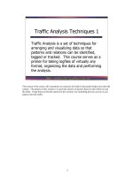
OSPF implements a two-layer hierarchy: the backbone (area 0) and areas off of
the backbone (areas 1–65,535), as is shown in Figure 11-1. This network includes
a backbone and three areas off of the backbone. Through a correct IP addressing
design, you should be able to summarize routing information between areas. By
summarizing your routing information, perhaps one summarized route for each area,
you are reducing the amount of information that routers need to know about. For
instance, each area in Figure 11-1 is assigned a separate Class B network number.
Through summarization on the border routers between areas, other areas would not
need to see all the Class B subnets—only the summarized network numbers.
For instance, Area 2 doesn’t need to see all of the subnets of Area 3’s 172.18.0.0
network number, since there are only two paths out of Area 2 to the backbone. Area 2,
however, needs to see all of its internal subnets to create optimized routing tables to
reach internal networks. Therefore, each area should contain specific routes only for
OSPF
3
CertPrs8 / CCNA Cisco Certified Network Associate Study Guide / Deal / 222934-9 / Chapter 11
Remember the advantages
and disadvantages of OSPF, listed in the
preceding bullets. Also, classless protocols
include the subnet mask value along with
the route when advertising routing
information: distance vector protocols do
not include the subnet mask in their routing
updates.
D:\omh\CertPrs8\934-9\ch11.vp
Monday, August 04, 2003 12:13:41 PM
Color profile: Generic CMYK printer profile
Composite Default screen
its own areas and summarized routes to reach other areas. By performing this
summarization, the routers have a smaller topology database (they know only
about links in their own area and the summarized routes) and their routing tables
are smaller (they know only about their own
area’s routes and the summarized routes).
Through a correct hierarchical design, you
can scale OSPF to very large sizes.
Note that the CCNA exam focuses on
single-area designs, and throughout the rest
of the sections, the material covers only
single-area concepts. The BSCI exam for the CCNP and CCDP certifications,
however, spends a lot of time on both single- and multi-area designs. Designing
a multi-area OSPF network can become very complicated and requires a lot of
networking knowledge and skill.
4
Chapter 11: Configuring Advanced Routing Protocols
CertPrs8 / CCNA Cisco Certified Network Associate Study Guide / Deal / 222934-9 / Chapter 11
FIGURE 11-1 OSPF hierarchical design
OSPF supports a two-layer
hierarchy: the backbone (area 0) and
areas connected to the backbone.
D:\omh\CertPrs8\934-9\ch11.vp
Monday, August 04, 2003 12:13:41 PM
Color profile: Generic CMYK printer profile
Composite Default screen
Metric Structure
Unlike RIP, which uses hop count as a metric, OSPF uses cost. Cost is actually the
inverse of the bandwidth of a link: the faster the speed of the connection, the lower
the cost. The most preferred path is the one with the lowest cost. By using cost as a
metric, OSPF will choose more intelligent paths than RIP.
Remember that on synchronous serial links, no matter what the clock rate of the
physical link is, the bandwidth always defaults to 1544 Kbps. You’ll want to code this
correctly with the bandwidth Interface Subconfiguration mode command. This is
important if you have multiple synchronous serial paths to a destination, especially if
they have different clock rates. OSPF supports load balancing of up to six equal-cost
paths to a single destination. However, if you don’t configure the bandwidth metric
correctly on your serial interfaces, your router might accidentally include paths with
different clock rates, which can cause load-balancing issues.
For example, if you have one serial connection clocked at 1,544 Kbps and another
clocked at 256 Kbps and you don’t change the bandwidth values, OSPF will see both
connections as 1,544 Kbps and attempt to use
both when reaching a single destination. This
can create throughput problems when the router
is performing load balancing—half of the traffic
will go down one link and half down the other,
creating congestion problems.
Router Identities
Each router in an OSPF network needs a unique ID. The ID is used to provide a unique
identity to the OSPF router. This is included in any OSPF messages the router generates.
The router ID is chosen according to one of the two following criteria:
■
The highest IP address on its loopback interfaces (this is a logical interface on
a router)
■
The highest IP address on its active interfaces
If you have an IP address on an active loopback
interface, the router will use the highest IP address
from the bunch for its router ID. The router ID is
used by the router to announce itself to the other
OSPF routers in the network. This ID must
be unique. If you have no loopback interfaces
OSPF
5
CertPrs8 / CCNA Cisco Certified Network Associate Study Guide / Deal / 222934-9 / Chapter 11
OSPF uses cost as a metric,
which is the inverse of the bandwidth of
a link.
Remember how a router
acquires its router ID for OSPF.
D:\omh\CertPrs8\934-9\ch11.vp
Monday, August 04, 2003 12:13:42 PM
Color profile: Generic CMYK printer profile
Composite Default screen
configured, then the router will use the highest IP address from one of its physical
interfaces. If there is no active interface, the OSPF process will not start and
therefore you will not have any OSPF routes in your routing table. It is highly
recommended that you use a loopback interface because it is always up and thus
the router can obtain a router ID.
Finding Neighbors
OSPF learns about its neighbors and builds its adjacency and topology tables by sharing
LSAs. There are different types of LSAs. When learning about the neighbors that a
router is connected to, as well as keeping tabs on known neighbors, OSPF routers will
generate hello LSAs every 10 seconds. When a neighbor is discovered and an adjacency
is formed with the neighbor, a router expects to see hello messages from the neighbor. If
a neighbor is not seen within the dead interval time, which defaults to 40 seconds, the
neighbor is declared dead. When this occurs, the router will advertise this information,
via an LSA message, to other neighboring OSPF routers.
Whereas RIP accepts routing updates from just about any other RIP router, OSPF
has some rules concerning if and how routing information should be shared. First,
before a router will accept any routing information from another OSPF router, they
have to build an adjacency with each other on their connected interfaces. When this
adjacency is built, the two routers (on the connected interfaces) are called neighbors,
which indicates a special relationship between the two. In order for two routers to
become neighbors, the following must match on each router:
■
The area number and its type
■
The hello and dead interval timers
■
The OSPF password (optional), if it is configured
■
The area stub flag (used to contain OSPF messages and routing information,
this is beyond the scope of this book)
If these items do not match, then the routers will not form an adjacency and will
ignore each other’s routing information.
Let’s assume that you turned on all your routers simultaneously on a segment. In
this case, the OSPF routers will go through three states called the exchange process:
1. Down state The new router has not exchanged any OSPF information with
any other router.
2. Init state A destination router has received a new router's hello and adds it to
its neighbor list (assuming that certain values match). Note that communication
is only unidirectional at this point.
6
Chapter 11: Configuring Advanced Routing Protocols
CertPrs8 / CCNA Cisco Certified Network Associate Study Guide / Deal / 222934-9 / Chapter 11
D:\omh\CertPrs8\934-9\ch11.vp
Monday, August 04, 2003 12:13:42 PM
Color profile: Generic CMYK printer profile
Composite Default screen
3. Two-Way state The new router receives a unidirectional reply to its initial
hello packet and adds the destination router to its neighbor database.
Once the routers have entered a two-way state, they are considered neighbors. At
this point, an election process takes place to elect the designated router (DR) and
the backup designated router (BDR).
Designated and Backup Designated Routers
An OSPF router will not form adjacencies to just any router. Instead, a client/server
design is implemented in OSPF. For each network multi-access segment, there is a DR
and a BDR as well as other routers. As an example, if you have ten VLANs in your
switched area, you’ll have ten DRs and ten BDRs. The one exception of a segment
not having these two routers is on a WAN point-to-point link.
When an OSPF router comes up, it forms adjacencies with the DR and the BDR
on each multi-access segment that it is connected to. Any exchange of routing
information is between these DR/BDR routers and the other OSPF neighbors on
a segment (and vice versa). An OSPF router talks to a DR using the IP multicast
address of 224.0.0.6. The DR and the BDR talk to all routers using the 224.0.0.5
multicast IP address.
The OSPF router with the highest priority becomes the DR for the segment. If
there is a tie, the router with the highest router ID will become the DR. By default,
all routers have a priority of 1 (priorities can range 0–255). If the DR fails, the BDR
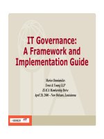
is promoted to DR and another router is elected as the BDR. Figure 11-2 shows an
example of the election process, where router E is elected as the DR and router B,
the BDR.
OSPF
7
CertPrs8 / CCNA Cisco Certified Network Associate Study Guide / Deal / 222934-9 / Chapter 11
OSPF routers use
Link State Advertisements (LSAs) to
communicate with each other. One type
of LSA is a hello, which is used to form
neighbor relationships and as a keep-alive
function. Hellos are generated every ten
seconds. When sharing link information
(directly connected routes), links are sent
to the DR (224.0.0.6) and the DR
disseminates this to everyone (224.0.0.5)
else on the segment. The router with the
highest priority (or highest router ID)
becomes the DR. This process is true
for multi-access segments, but not
point-to-point links, where DRs are
not necessary.
D:\omh\CertPrs8\934-9\ch11.vp
Monday, August 04, 2003 12:13:42 PM
Color profile: Generic CMYK printer profile
Composite Default screen
Sharing Routing Information
After electing the DR/BDR pair, the routers continue to generate hellos to maintain
communication. This is considered an exstart state, in which the OSPF routers are
ready to share link state information. The process the routers go through is called an
exchange protocol:
1. Exstart state The DR and BDR form adjacencies with the other OSPF
routers on the segment, and then within each adjacency, the router with the
highest router ID becomes the master and starts the exchange process first
(shares its link state information)—note that the DR is not necessarily the
master for the exchange process. The remaining router in the adjacency will
be the slave.
2. Exchange state The master starts sharing link state information first, with
the slave. These are called DBDs (database description packets), also referred
to as DDPs. The DBDs contain the link-state type, the ID of the advertising
router, the cost of the advertised link, and the sequence number of the link.
The slave responds back with an LSACK—an acknowledgment to the DBD
from the master. The slave then compares the DBD's information with its own.
3. Loading state If the master has more up-to-date information than the slave,
the slave will respond to the master's original DBD with an LSR (Link State
Request). The master will then send a LSU (Link State Update) with the
detailed information of the links to the slave. The slave will then incorporate
this into its local link state database. Again, the slave will generate an LSACK
8
Chapter 11: Configuring Advanced Routing Protocols
CertPrs8 / CCNA Cisco Certified Network Associate Study Guide / Deal / 222934-9 / Chapter 11
FIGURE 11-2
DR and BDR
election process
D:\omh\CertPrs8\934-9\ch11.vp
Monday, August 04, 2003 12:13:42 PM
Color profile: Generic CMYK printer profile
Composite Default screen
to the master to acknowledge the fact that it received the LSU. If a slave has
more up-to-date information, it will repeat the "exchange" and "loading" states.
4. Full state Once the master and the slave are synchronized, they are considered
to be in a full state.
To summarize these four steps, OSPF routers share a type of LSA message in order
to disclose information about available routes. Basically, an LSA update message
contains a link and a state, as well as other information. A link is the router interface
on which the update was generated (a connected route). The state is a description of
this interface, including the IP address configured on it as well as the relationship this
router has with its neighboring router. However, OSPF routers will not share this
information with just any OSPF router.
OSPF uses incremental updates after entering a full state. This means that
whenever changes take place, only the change is shared with the DR, which will
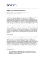
then share this information with other routers on the segment. Figure 11-3 shows
an example of this. In this example, Network Z, connected to router C, goes down.
Router C sends a multicast to the DR and the BDR (with a destination multicast
address of 224.0.0.6), telling them about this change. Once the DR and the BDR
incorporate the change internally, the DR then tells the other routes on the
segment (via a multicast message sent to 224.0.0.5, which is all OSPF routers)
about the change concerning Network Z. Any router receiving the update will
then share this update to the DRs of other segments that they are connected to.
Note that the communications between OSPF routers is connection-oriented, even
though multicasts are used. For example, if a router tells a DR about a change, the
DR acknowledges this new piece of information. Likewise, when the DR shares this
information with the other routers on the segment, the DR expects acknowledgments
back from each of these neighbors. Remember that when an OSPF router exchanges
OSPF
9
CertPrs8 / CCNA Cisco Certified Network Associate Study Guide / Deal / 222934-9 / Chapter 11
OSPF routers share
information about their connected routes
with the DR, which includes the link-state
type, the ID of the advertising router,
the cost of the advertised link, and the
sequence number of the link. This is
different from distance vector protocols.
Distance vector protocols share their
entire routing table with their neighbors
with the exception of routes learned
from the same interface of the neighbor
(split horizon) and the connected route
of the interface where the neighbor
resides.
D:\omh\CertPrs8\934-9\ch11.vp
Monday, August 04, 2003 12:13:42 PM
Color profile: Generic CMYK printer profile
Composite Default screen
updates with another, the process requires an acknowledgment: this ensures that router
or routers have received the update.
The exception to the incremental update process is that the DR floods its
database every 30 minutes to ensure that all of the routers on the segment have
the most up-to-date link state information.
It does this with a destination address of
224.0.0.5 (all OSPF routers on the segment).
When building the routing table using link
state information, an OSPF router can keep up
to six paths to a destination in its routing table.
The only restriction is that the paths must have
the same cost.
Configuring OSPF
Configuring OSPF is slightly different from configuring RIP or IGRP. When configuring
OSPF, use the following syntax:
Router(config)# router ospf
process_ID
Router(config-router)# network
IP_address wildcard_mask
area
area_#
The process_ID is locally significant and is used to differentiate between different
OSPF processes running on the router. Your router might be a boundary router
10
Chapter 11: Configuring Advanced Routing Protocols
CertPrs8 / CCNA Cisco Certified Network Associate Study Guide / Deal / 222934-9 / Chapter 11
FIGURE 11-3
LSA update
process
A two-way state indicates
that two OSPF routers are neighbors. A
full state indicates the completion of
sharing of links between routers.
D:\omh\CertPrs8\934-9\ch11.vp
Monday, August 04, 2003 12:13:42 PM
Color profile: Generic CMYK printer profile
Composite Default screen
between two OSPF autonomous systems, and to differentiate them on your router,
you'll give them unique process IDs. Note that these numbers do not need to match
between different routers and that they have nothing to do with autonomous system
numbers.
When specifying what interfaces go into an area for OSPF, use the network
command. As you can see in the preceding example, the syntax of this command is
different than for RIP’s and IGRP’s configuration, where you specify only a class
address. OSPF is classless. With this command, you can be very specific about what
interface belongs to a particular area. The syntax of this command is to list an IP
address followed by a wildcard mask. This is different from a subnet mask. A wildcard
mask tells the router the interesting component of the address—in other words,
what part of the address it should match on. This mask is also used with access
lists, which are discussed in Chapter 13.
A wildcard mask is 32 bits in length.A0inabitposition means there must be a
match, and a 1 in a bit position means the router doesn’t care. Actually, a wildcard
mask is an inverted subnet mask, with the 1’s and 0’s switched. Using a wildcard mask,
you can be very specific about which interfaces belong to which areas. The last part
of the command tells the router which area these addresses on the router belong to.
Let’s look at some code examples to see how the wildcard mask works. I’ll use the
router shown in Figure 11-4 as an illustration.
Router(config)# router ospf 1
Router(config-router)# network 10.1.1.1 0.0.0.0 area 0
Router(config-router)# network 10.1.2.1 0.0.0.0 area 0
Router(config-router)# network 172.16.1.1 0.0.0.0 area 0
Router(config-router)# network 172.16.2.1 0.0.0.0 area 0
In this example, the interfaces with addresses of 10.1.1.1, 10.1.2.1, 172.16.1.1,
and 172.16.1.1 all are associated with area 0. A wildcard mask of 0.0.0.0 says that
there must be an exact match against the address in order to place it into area 0.
Here’s another example:
Router(config)# router ospf 1
Router(config-router)# network 10.0.0.0 0.255.255.255 area 0
Router(config-router)# network 172.16.0.0 0.0.255.255 area 0
In this example, interfaces beginning with 10 or 172.16 are to be associated with
area 0. Or, if all the interfaces on your router belonged to the same area, you could
use this configuration:
Router(config)# router ospf 1
Router(config-router)# network 0.0.0.0 255.255.255.255 area 0
OSPF
11
CertPrs8 / CCNA Cisco Certified Network Associate Study Guide / Deal / 222934-9 / Chapter 11
D:\omh\CertPrs8\934-9\ch11.vp
Monday, August 04, 2003 12:13:43 PM
Color profile: Generic CMYK printer profile
Composite Default screen
In this example, all interfaces are placed in area 0. As you can see, OSPF is very
flexible in allowing you to specify which interface or interfaces will participate in
OSPF and which area or areas they will belong to.
11.01. The CD contains a multimedia demonstration of configuring OSPF
on a router.
Loopback Interfaces
A loopback interface is a logical, virtual interface on a router. By default, the router
doesn’t have any loopback interfaces, but they can easily be created. All IOS platforms
support loopback interfaces, and you can create as many of these interfaces as you
need. These interfaces are treated as physical interfaces on a router: you can assign
addressing information to them, include their network numbers in routing updates,
and even terminate IP connections on them, like telnet. Here are some reasons you
might want to create a loopback interface:
12
Chapter 11: Configuring Advanced Routing Protocols
CertPrs8 / CCNA Cisco Certified Network Associate Study Guide / Deal / 222934-9 / Chapter 11
FIGURE 11-4
OSPF network
configuration
example
When configuring the
OSPF routing process, you must specify
a process ID. Unlike in RIP or IGRP, the
network
statement allows you to specify
an IP address and a wildcard mask, which
is an inverted subnet mask. You must
also specify the area that this address
or addresses will belong to:
network
network_# wildcard_mask area
area_#
.
D:\omh\CertPrs8\934-9\ch11.vp
Monday, August 04, 2003 12:13:43 PM
Color profile: Generic CMYK printer profile
Composite Default screen
■
To assign a router ID to an OSPF router
■
To use for testing purposes, since this interface is always up
■
To terminate special connections, such as GRE tunnels or IPSec
connections, since this interface is always up
To create a loopback interface, use the following command:
Router(config)# interface loopback
port_#
Router(config-if)# ip address
IP_address subnet_mask
As you can see, creating a loopback interface
is easy. You can specify port numbers from 0
to 2147483647. The number you use is only
locally significant. Once you enter the loopback
interface, you can execute almost any interface
command on it; for instance, you can assign it an
IP address with the ip address command.
11.02. The CD contains a multimedia demonstration of creating a loopback
interface on a router.
Changing Metrics
You have two ways to affect the cost metric that OSPF uses in picking the best-cost routes
for the routing table. First, remember that the cost metric is the inverse of the accumulated
bandwidth values of routers’ interfaces. The default
measurement that Cisco uses in calculating the cost
metric is: cost = 10
8
/(interface bandwidth). You can
also affect the value of the cost by changing the 10
8
value with the auto-cost reference-
bandwidth command. Table 11-1 contains
some costs for different interface types:
To change the cost of an interface, use the following configuration:
Router(config)# interface
type
[
slot_#
/]
port_#
Router(config-if)# ip ospf cost
cost_value
Notice that the cost is assigned within an interface. This value can range from 1
to 65,535. Note that each vendor might use a different calculation to come up with
a cost value. It is very important that the costs for a link match for every router on a
OSPF
13
CertPrs8 / CCNA Cisco Certified Network Associate Study Guide / Deal / 222934-9 / Chapter 11
A loopback interface
is a logical interface that always remains
up. Use the
interface loopback
command to create it.
Remember the OSPF
interface costs in Table 11-1; especially for
serial connections.
D:\omh\CertPrs8\934-9\ch11.vp
Monday, August 04, 2003 12:13:43 PM
Color profile: Generic CMYK printer profile
Composite Default screen
given segment. Mismatched cost values on a segment can cause routers to continually
run the SPF algorithm, greatly affecting the routers’ performance.
Normally, you won’t be changing the default cost values on an interface. However,
since OSPF uses the inverse of bandwidth as a metric, and serial interfaces default to a
bandwidth of 1,544 Kbps, you will definitely want to match the bandwidth metric on
the serial interface to its real clock rate. To configure the bandwidth on your router's
interfaces, use the following command:
Router(config) interface
type
[
slot_#
/]
port_#
Router(config-if)# bandwidth
speed_in_Kbps
As an example, if the clock rate were 64,000, you would use the following
command to correctly configure the bandwidth: bandwidth 64. Note that the
speed is in Kbps. For example, let’s assume you configured the bandwidth with
this: bandwidth 64000. By doing this, the router would assume the bandwidth
metric of the interface is 64 Mbps, not Kbps.
11.03. The CD contains a multimedia demonstration of changing OSPF
metrics on a router.
14
Chapter 11: Configuring Advanced Routing Protocols
CertPrs8 / CCNA Cisco Certified Network Associate Study Guide / Deal / 222934-9 / Chapter 11
Bandwidth Value Interface Type
1785 56 Kbps serial line
1652 64 Kbps serial line
64 T1
25 4Mb Token Ring
10 Ethernet
6 16Mb Token Ring
1 Fast Ethernet and FDDI
TABLE 11-1
OSPF Costs
for Different
Interfaces
The
bandwidth
command
should be used on synchronous serial
interfaces to match the bandwidth metric
to the clocked rate of the interface.
Synchronous serial interfaces default
to a bandwidth metric of 1,544 Kbps.
D:\omh\CertPrs8\934-9\ch11.vp
Monday, August 04, 2003 12:13:43 PM
Color profile: Generic CMYK printer profile
Composite Default screen
Troubleshooting OSPF
Once you have configured OSPF, you have a variety of commands available to view
and troubleshoot your configuration and operation of OSPF:
■
show ip protocols
■
show ip route
■
show ip ospf interface
■
show ip ospf neighbor
■
debug ip ospf adj
■
debug ip ospf events
■
debug ip ospf packet
The following sections cover these commands.
The show ip protocols Command
The show ip protocols command displays all of the IP routing protocols that
you have configured and are running on your router. Here’s an example of this command
with OSPF:
Router# show ip protocols
Routing Protocol is "ospf 1"
Outgoing update filter list for all interfaces is not set
Incoming update filter list for all interfaces is not set
Router ID 192.168.100.1
Number of areas in this router is 1. 1 normal 0 stub 0 nssa
Maximum path: 4
Routing for Networks:
0.0.0.0 255.255.255.255 area 0
Routing Information Sources:
Gateway Distance Last Update
192.168.1.100 110 00:00:24
192.168.100.1 110 00:00:24
Distance: (default is 110)
In this example, the router’s ID is 192.168.100.1. All interfaces are participating in
OSPF (0.0.0.0 255.255.255.255) and are in area 0. There are two OSPF routers in this
network: 192.168.1.100 (another router) and 192.168.100.1 (this router). Notice that
the default administrative distance is 110.
OSPF
15
CertPrs8 / CCNA Cisco Certified Network Associate Study Guide / Deal / 222934-9 / Chapter 11
D:\omh\CertPrs8\934-9\ch11.vp
Monday, August 04, 2003 12:13:43 PM
Color profile: Generic CMYK printer profile
Composite Default screen
11.04. The CD contains a multimedia demonstration of using the
show ip
protocols
command on an OSPF router.
The show ip route Command
Your router keeps a list of the best paths to destinations in a routing table. To view the
routing table, use the show ip route command:
Router# show ip route
Codes: C - connected, S - static, I - IGRP, R - RIP,
M - mobile, B - BGP, D - EIGRP, EX - EIGRP external,
O - OSPF, IA - OSPF inter area, N1 - OSPF NSSA
external type 1, N2 - OSPF NSSA external type 2,
E1 - OSPF external type 1, E2 - OSPF external type 2,
E - EGP, i - IS-IS, L1 - IS-IS level-1,
L2 - IS-IS level-2, * - candidate default,
U - per-user static route, o - ODR,
T - traffic engineered route
Gateway of last resort is not set
10.0.0.0/24 is subnetted, 1 subnets
O 10.0.1.0 [110/65] via 192.168.1.100, 00:04:18, Serial0
C 192.168.1.0/24 is directly connected, Serial0
C 192.168.100.0/24 is directly connected, Ethernet0
In this example, there is one OSPF route
(O): 10.0.1.0. This route has an administrative
distance of 110, has a cost of 65, and can be
reached via neighbor 192.168.1.100.
11.05. The CD contains a multimedia demonstration of using the
show ip
route
command on an OSPF router.
The show ip ospf interface Command
On an interface-by-interface basis, your OSPF router keeps track of what area an
interface belongs to and what neighbors, if any, are connected to the interface. To
view this, use the show ip ospf interface command:
Router# show ip ospf interface
Ethernet 1 is up, line protocol is up
Internet Address 172.16.255.1/24, Area 0
Process ID 100, Router ID 172.16.255.1, Network Type BROADCAST, Cost: 10
16
Chapter 11: Configuring Advanced Routing Protocols
CertPrs8 / CCNA Cisco Certified Network Associate Study Guide / Deal / 222934-9 / Chapter 11
OSPF routes show up
as an
O
in the output of the
show ip
route
command.
D:\omh\CertPrs8\934-9\ch11.vp
Monday, August 04, 2003 12:13:43 PM
Color profile: Generic CMYK printer profile
Composite Default screen
Transmit Delay is 1 sec, State DROTHER, Priority 1
Designated Router id 172.16.255.11, Interface address 172.16.255.11
Backup Designated router id 172.16.255.10, Interface addr 172.16.255.10
Timer intervals configured, Hello 10, Dead 40, Wait 40, Retransmit 5
Hello due in 0:00:03
Neighbor Count is 3, Adjacent neighbor count is 2
Adjacent with neighbor 172.16.255.10 (Backup Designated Router)
Adjacent with neighbor 172.16.255.11 (Designated Router)
In this example, the router ID is 172.16.255.1. Its state is DROTHER, which
means that it is not the DR or BDR. Actually, the DR is 172.16.255.11 and the BDR
is 172.16.255.10. There are a total of three neighbors, with two adjacencies—
remember that adjacencies are built only between routers and the DR and BDR.
11.06. The CD contains a multimedia demonstration of using the
show ip
ospf interface
command on an OSPF router.
The show ip ospf neighbor Command
To see all of your router’s OSPF neighbors, use the show ip ospf neighbor
command:
Router# show ip ospf neighbor
ID Pri State Dead Time Address Interface
172.16.255.11 1 FULL/DR 0:00:31 172.16.255.11 Ethernet0
172.16.255.10 1 FULL/BDR 0:00:33 172.16.255.10 Ethernet0
172.16.255.9 1 2WAY/DROTHER 0:00:35 172.16.255.9 Ethernet0
172.16.254.2 1 FULL/DR 0:00:39 172.16.254.2 Serial0.1
In this example, there are three routers
connected to Ethernet0: 172.16.255.11 is a
DR, 172.16.255.10 is a BDR, and 172.16.255.9
is another OSPF router (DROTHER). Notice
that for the DR and the BDR, the state is full,
which is to be expected, since this router and
OSPF
17
CertPrs8 / CCNA Cisco Certified Network Associate Study Guide / Deal / 222934-9 / Chapter 11
The
show ip ospf
interface
command displays your
router’s ID, the ID of the DR and BDR,
the hello timer (10 seconds), the dead
interval (40 seconds), the number of
neighbors, and the number of adjacencies.
The
show ip ospf
neighbor
command lists all of the router’s
OSPF neighbors, their OSPF states, their
router IDs, and which interface the
neighbors are connected to.
D:\omh\CertPrs8\934-9\ch11.vp
Monday, August 04, 2003 12:13:44 PM
Color profile: Generic CMYK printer profile
Composite Default screen
the DR/BDR share routing information with each other. The DROTHER router is
in a two-way state, which indicates that the router is a neighbor, but this router and
the DROTHER router will not share routing information directly with each other.
11.07. The CD contains a multimedia demonstration of using the
show ip
ospf neighbor
command on an OSPF router.
The debug ip ospf adj Command
For more detailed troubleshooting, you can use debug commands. If you want to view
the adjacency process that a router builds to other routers, use the debug ip ospf
adj command:
Router# debug ip ospf adj
172.16.255.11 on Ethernet0, state 2WAY
OSPF: end of Wait on interface Ethernet0
OSPF: DR/BDR election on Ethernet0
OSPF: Elect BDR 172.16.255.10
OSPF: Elect DR 172.16.255.11
DR: 172.16.255.11 (Id) BDR: 172.16.255.10 (Id)
OSPF: Send DBD to 172.16.255.11 on Ethernet0
seq 0x10DB opt 0x2 flag 0x7 len 32
OSPF: Build router LSA for area 0, router ID 172.16.255.11
In this example, you can see the election process for the DR and BDR and the
sharing of links (DBDs) with the DR.
11.08. The CD contains a multimedia demonstration of using the
debug ip
ospf adj
command on an OSPF router.
The debug ip ospf events Command
If you want to view OSPF events on your router, use the debug ip ospf events
command:
Router# debug ip ospf events
4d02h: OSPF: Rcv hello from 192.168.1.100 area 0 from Serial0
192.168.1.100
4d02h: OSPF: End of hello processing
In this example, the router received a hello packet from 192.168.1.00, which
is connected to Serial0. Other kinds of information that you might see are:
■
Hello intervals that do not match for routers on a segment
18
Chapter 11: Configuring Advanced Routing Protocols
CertPrs8 / CCNA Cisco Certified Network Associate Study Guide / Deal / 222934-9 / Chapter 11
D:\omh\CertPrs8\934-9\ch11.vp
Monday, August 04, 2003 12:13:44 PM
Color profile: Generic CMYK printer profile
Composite Default screen
■
Dead intervals that do not match for routers on a segment
■
Mismatched subnet masks for OSPF routers on a segment
11.09. The CD contains a multimedia demonstration of using the
debug ip
ospf events
command on an OSPF router.
The debug ip ospf packet Command
If you want to view OSPF packet contents of LSAs, use the debug ip ospf
packet command:
Router# debug ip ospf packet
4d02h: OSPF: rcv. v:2 t:1 l:48 rid:192.168.1.100
aid:0.0.0.0 chk:15E4 aut:0 auk: from Serial0
Table 11-2 explains the values shown in this
command.
11.10. The CD contains a multimedia demonstration of using the
debug ip
ospf packet
command on an OSPF router.
OSPF
19
CertPrs8 / CCNA Cisco Certified Network Associate Study Guide / Deal / 222934-9 / Chapter 11
Field Value Explanation
Aid: OSPF Area ID number
Auk: OSPF authentication key used for neighbor authentication
Aut: Type of OSPF authentication (0-none, 1-simple password,
2-MD5 hashing)
Keyid: MD5 key value if this authentication mechanism is enabled
L: Length of the packet
Rid: OSPF router ID
Seq: Sequence number
T: OSPF packet type (1-hello, 2-data description, 3-link state
request, 4-link state update, 5-link state acknowledgment
V: OSPF version number
TABLE 11-2
Field Values of
the debug ip
ospf packet
Command
Be familiar with the terms
in Table 11-2.
D:\omh\CertPrs8\934-9\ch11.vp
Monday, August 04, 2003 12:13:44 PM
Color profile: Generic CMYK printer profile
Composite Default screen
EXERCISE 11-1
ON THE CD
Configuring OSPF
These last few sections dealt with the configuring OSPF on a router. This exercise
will help you reinforce this material for setting up and troubleshooting OSPF. You’ll
perform this lab using Boson’s NetSim™ simulator. This exercise has you set OSPF on
the two routers (2600 and 2500). You can find a picture of the network diagram for
Boson’s NetSim™ simulator in the Introduction of this book. After starting up the
simulator, click on the LabNavigator button. Next, double-click on Exercise 11-1 and
click on the Load Lab button. This will load the lab configuration based on Chapter 5’s
and 7’s exercises.
1. On the 2600, verify that the fa0/0 and s0 interfaces are up. If not, bring
them up. Examine the IP addresses configured on the 2600 and look at its
routing table.
At the top of the simulator in the menu bar, click on the eRouters icon and
choose 2600. On the 2600, use the show interfaces command to verify
your configuration. If fa0/0 and s0 are not up, go into the interfaces (fa0/0
and s0) and enable them: configure terminal, interface
type
port
, no shutdown, end, show interfaces. Use the show ip
route command. You should have two connected networks: 192.168.1.0
connected to fa0/0 and 192.168.2.0 connected to s0.
2. On the 2500, verify that the e0 and s0 interfaces are up. If not, bring them
up. Examine the IP addresses configured on the 2500 and look at its routing
table.
At the top of the simulator in the menu bar, click on the eRouters icon and
choose 2500. On the 2500, verify that the e0 and s0 interfaces are up. If not,
bring them up: configure terminal, interface
type port
, no
shutdown, end, show interfaces. Use the show interfaces
command to verify that the IP addresses you configured on Chapter 5 are still
there. Use the show ip route command. You should have two connected
networks: 192.168.3.0 connected to e0 and 192.168.2.0 connected to s0.
3. Test connectivity between Host1 and the 2600. Test connectivity between
Host3 and the 2500. Test connectivity between Host3 and Host1.
20
Chapter 11: Configuring Advanced Routing Protocols
CertPrs8 / CCNA Cisco Certified Network Associate Study Guide / Deal / 222934-9 / Chapter 11
D:\omh\CertPrs8\934-9\ch11.vp
Monday, August 04, 2003 12:13:44 PM
Color profile: Generic CMYK printer profile
Composite Default screen
At the top of the simulator in the menu bar, click on the eStations icon and
choose Host1. From Host1, ping the 2600: ping 192.168.1.1. The ping
should be successful. At the top of the simulator in the menu bar, click on
the eStations icon and choose Host3. From Host3, ping the 2500 router: ping
192.168.3.1. The ping should be successful. From Host3, ping Host 1:
ping 192.168.1.10. The ping should fail: there is no route from the
2500 to this destination (look at the 2500’s routing table: it doesn’t list
192.168.1.0/24).
4. Enable OSPF on the 2600 and 2500 routers, using a process ID of 1, and put
all interfaces in area 0.
At the top of the simulator in the menu bar, click on the eRouters
icon and choose 2600. On the 2600 router, configure the following:
configure terminal, router ospf 1, network 0.0.0.0
255.255.255.255 area 0, end. At the top of the simulator in the
menu bar, click on the eRouters icon and choose 2600. On the 2500 router,
configure the following: configure terminal, router ospf 1,
network 0.0.0.0 255.255.255.255 area 0, end.
5. On the 2600 and 2500, verify the operation of OSPF. Is either router a DR
or BDR on the WAN link?
At the top of the simulator in the menu bar, click on the eRouters icon and
choose 2600. Use the show ip protocols command to make sure that
OSPF is configured—check for the neighboring router’s update. Use the show
ip route command and look for the remote LAN network number as a
RIP (O) entry in the routing table. Use the show ip ospf neighbor
command to view your neighboring router. Neither should be a DR or BDR
on the serial link, since point-to-point connections don’t use DRs and BDRs.
At the top of the simulator in the menu bar, click on the eRouters icon and
choose 2500. Use the same above commands, show ip protocols,
show ip route, and show ip ospf neighbor, to verify the
operation of OSPF.
6. On Host1, test connectivity to Host3.
At the top of the simulator in the menu bar, click on the eStations icon and
choose Host1. On Host1, execute this: ping 192.168.3.2. The ping
should be successful.
OSPF
21
CertPrs8 / CCNA Cisco Certified Network Associate Study Guide / Deal / 222934-9 / Chapter 11
D:\omh\CertPrs8\934-9\ch11.vp
Monday, August 04, 2003 12:13:44 PM
Color profile: Generic CMYK printer profile
Composite Default screen
EXERCISE 11-2
ON THE CD
Troubleshooting OSPF
The last exercise dealt with configuring OSPF on the 2600 and 2500 routers. This
exercise will help you introduce you to an already configured network, but with some
configuration issues which are preventing OSPF connectivity. You’ll perform this lab
using Boson’s NetSim™ simulator. You can find a picture of the network diagram for
Boson’s NetSim™ simulator in the Introduction of this book. After starting up the
simulator, click on the LabNavigator button. Next, double-click on Exercise 11-2 and
click on the Load Lab button. This will load the lab configuration based on Chapter 5’s
and 7’s exercises (with problems, of course.
Lets’ start with your problem: Host1 cannot ping Host3. Your task is to figure
out what the problems are and fix them: there are three problems. In this example,
OSPF has been preconfigured on the routers. I would recommend that you try this
troubleshooting process on your own first; and if you have problems, come back to
the steps and solutions provided below.
1. Test connectivity from Host1 to Host3 with ping as well as from Host1 to
its default gateway.
At the top of the simulator in the menu bar, click on the eStations icon and
choose Host1. On Host1, ping Host3: ping 192.168.3.2. Note that the
ping fails. Ping the default gateway address: ping 192.168.1.1. The ping
should fail, indicating that at least layer-3 is functioning between Host1 and
the 2600. Examine the IP configuration on Host1 by executing: winipcfg.
Make sure the IP addressing information is correct: IP address of 192.168.1.10,
subnet mask of 255.255.255.0, and default gateway address of 192.168.1.1. Notice
that the IP address is 192.168.100.10. Change this address to 192.168.1.10. Click
on the OK button to save your changes and close winipcfg. Try pinging the
2600 again: ping 192.168.1.1. The ping should succeed. At the top of
the simulator in the menu bar, click on the eStations icon and choose Host1.
On Host1, ping Host3: ping 192.168.3.2. Note that the ping still fails.
2. Test connectivity from Host3 to its default gateway.
At the top of the simulator in the menu bar, click on the eStations icon
and choose Host3. Examine the IP configuration on Host3 by executing:
winipcfg. Make sure the IP addressing information is correct: IP address
of 192.168.3.2, subnet mask of 255.255.255.0, and default gateway address of
192.168.3.1. Click on the Cancel button to close winipcfg. Ping the default
gateway address: ping 192.168.3.1. The ping should be fail, indicating
22
Chapter 11: Configuring Advanced Routing Protocols
CertPrs8 / CCNA Cisco Certified Network Associate Study Guide / Deal / 222934-9 / Chapter 11
D:\omh\CertPrs8\934-9\ch11.vp
Monday, August 04, 2003 12:13:44 PM
Color profile: Generic CMYK printer profile
Composite Default screen
that there is a problem between Host3 and the 2500. In this example, layer-2 is
functioning correctly; therefore, it must be a problem with the 2500.
3. Check the interface statuses and IP configuration on the 2500 and verify
connectivity to the 2600. Also verify OSPF’s configuration.
At the top of the simulator in the menu bar, click on the eRouters icon and
choose 2500. Check the status of the interfaces: show interfaces. Notice
that the e0 is has the wrong IP address (192.168.30.1) and is disabled. Go into
e0, fix the IP address, and enable it: configure terminal, interface
e0, ip address 192.168.3.1, no shutdown, end. Verify the status
of the e0 interface: show interface e0. Try pinging Host3: ping
192.168.3.2. The ping should succeed. Try pinging the 2600’s serial0
interface: ping 192.168.2.1. The ping succeeds. Examine the 2500’s
OSPF configuration: show ip protocol. You should see OSPF as the
routing protocol and networks 192.168.2.0 and 192.168.3.0 included. From
this output, it looks like OSPF is configured correctly on the 2500. Save the
configuration on the router: copy running-config startup config.
4. Test connectivity from the 2500 to Host1. Examine the routing table.
From the 2500 router, test the connection to Host1: ping 192.168.1.10.
The ping should fail. This indicates a layer-3 problem between the 2500 and
Host1. Examine the routing table: show ip route. Notice that there are
only two connected routes (192.168.2.0/24 and 192.168.1.0/24), but no OSPF
routes.
5. Access the 2600 router and examine OSPF’s configuration. Fix the problem.
At the top of the simulator in the menu bar, click on the eRouters icon and
choose 2600. Examine the routing table: show ip protocol. What
networks are advertised by the 2600? You should see 192.168.100.0 and
192.168.2.0. Obviously, fa0/0’s interface isn’t included since 192.168.1.0
is not configured. Fix this configuration problem: configure terminal,
router ospf 1, no network 192.168.100.0 0.0.0.255
area 0, network 192.168.1.0 0.0.0.255 area 0, end.
Test connectivity to Host3: ping 192.168.3.2. The ping should be
successful. Save the configuration on the router: copy running-config
startup config.
6. Examine the routing table on the 2500. Test connectivity from the 2500
to Host1.
At the top of the simulator in the menu bar, click on the eRouters icon and
choose 2500. Examine the routing table: show ip route. Notice that
there are only two connected routes (192.168.2.0/24 and 192.168.1.0/24)
OSPF
23
CertPrs8 / CCNA Cisco Certified Network Associate Study Guide / Deal / 222934-9 / Chapter 11
D:\omh\CertPrs8\934-9\ch11.vp
Monday, August 04, 2003 12:13:44 PM
Color profile: Generic CMYK printer profile
Composite Default screen
and one OSPF route (192.168.1.0/24). From the 2500 router, test the connection
to Host1: ping 192.168.1.10. The ping should succeed.
7. Now test connectivity between Host1 and Host3.
At the top of the simulator in the menu bar, click on the eStations icon and
choose Host1. Test connectivity to Host3: ping 192.168.3.2. The ping
should be successful.
In the next section, you will learn about EIGRP and how to configure it.
EIGRP
The Enhanced Interior Gateway Routing Protocol (EIGRP) is a Cisco-proprietary
routing protocol for IP. It’s actually based on IGRP, with many enhancements built
into it. Because it has its roots in IGRP, the configuration is similar; however, it has
many link state characteristics that were added to it to allow EIGRP to scale to
enterprise network sizes. These characteristics include:
■
Fast convergence
■
Loop-free topology
■
VLSM and route summarization
■
Multicast and incremental updates
■
Routes for multiple routed protocols
The following sections cover some of the characteristics of EIGRP, its operation,
and its configuration.
Characteristics of EIGRP
Here is a brief comparison of EIGRP and IGRP:
■
Both offer load balancing across six paths (equal or unequal).
■
They have similar metric structures.
■
EIGRP has faster convergence (triggered updates and saving a neighbor’s
routing table locally).
■
EIGRP has less network overhead, since it uses incremental updates.
24
Chapter 11: Configuring Advanced Routing Protocols
CertPrs8 / CCNA Cisco Certified Network Associate Study Guide / Deal / 222934-9 / Chapter 11
D:\omh\CertPrs8\934-9\ch11.vp
Monday, August 04, 2003 12:13:45 PM
Color profile: Generic CMYK printer profile
Composite Default screen
EIGRP and IGRP use the same metric structure. Both can use bandwidth, delay,
reliability, and MTU when computing a best metric path to a destination. By default,
only bandwidth and delay are used in the metric computation.
One interesting point about these protocols is that if you have some routers
in your network running IGRP and others running EIGRP, and both sets have the
same autonomous system number, routing information will automatically be shared
between the two. The routers have to perform a conversion concerning the metrics.
Even though both protocols use the same metric components, they store them in
different size values: EIGRP uses a 32-bit metric, while IGRP uses a 24-bit metric.
When integrating the two protocols together, EIGRP routes are divided by 256 to
fit a 24-bit metric structure when passed to IGRP and IGRP routes are multiplied
by 256 to fit a 32-bit metric structure when passed to EIGRP.
EIGRP uses the Diffusing Update Algorithm (DUAL) to update the routing
table. This algorithm can enable very fast convergence by storing a neighbor’s
routing information in a local topology table. If a primary route in the routing table
fails, DUAL can take a backup route from the topology table and place this into the
routing table without necessarily having to talk to other EIGRP neighboring routers
to find an alternative path to the destination.
Unlike IGRP, EIGRP supports both automatic and manual summarization.
Remember that EIGRP is, at heart, a distance vector protocol, and therefore it will
automatically summarize routes across Class A, B, and C network boundaries. You can
also manually summarize within a class network, at your discretion. Configuration of
summarization is beyond the scope of this book, but it is covered in depth on Cisco’s
BSCI CCNP and CCDP exams.
One really unique feature of EIGRP is that it supports three routed protocols: IP,
IPX, and AppleTalk. In other words, EIGRP can route for all three of these protocols
simultaneously. If you are running these routed protocols in your environment, EIGRP is
a perfect fit. You only need to run one routing protocol for all three instead of a separate
routing protocol for each, definitely reducing your routing overhead.
EIGRP
25
CertPrs8 / CCNA Cisco Certified Network Associate Study Guide / Deal / 222934-9 / Chapter 11
The Cisco-proprietary
EIGRP routing process uses the same
metrics as IGRP. Unlike IGRP, EIGRP
supports multicast and incremental
updates, route summarization, and routing
for IP, IPX, and AppleTalk. The DUAL
algorithm is used to build a loop-free
routing topology.
D:\omh\CertPrs8\934-9\ch11.vp
Monday, August 04, 2003 12:13:45 PM
Color profile: Generic CMYK printer profile
Composite Default screen