Tài liệu DDR Lab Scenario 2 - Dialer Profiles with Authentication pdf
Bạn đang xem bản rút gọn của tài liệu. Xem và tải ngay bản đầy đủ của tài liệu tại đây (36.12 KB, 9 trang )
CertificationZone Page 1 of 9
/?Issue=32&IssueDate=03-01-2001&CP= 11/06/01
Date of Issue: 03-01-2001
Lab Scenario 2 - Dialer Profiles with
Authentication
by David Wolsefer
Introduction
Network Specifications
The Starting Configurations
Configure Global Commands
1. Configure the ISDN switch type on each router
2. No shut the BRI interfaces
3. Configure the Username Password Database
4. Define Interesting Traffic Using Dialer Lists
5. Configure the Rip version 2 routing protocol
Configure Physical Interface Commands
1. Enable encapsulation PPP
2. Specify ppp authentication chap
3. Configure SPIDs (If Necessary)
4. Assign the physical BRI interface to a dialer pool
Configure Logical Dialer Interface Commands
1. Create the logical dialer interface
2. Assign an IP address to the dialer interface
3. Enable PPP Encapsulation
4. Configure the Dialer Interface for PPP Authentication CHAP
5. Apply the dialer-list to define interesting traffic
6. Specify which dialer-pool to use
7. Configure the dialer remote name and string
8. Check our work
SOLUTION REVEALED
Router1's Final Configuration
Router2's Final Configuration
Introduction
This lab is designed to walk you through a basic dialer profile configuration and the special requirements this places
on PPP CHAP authentication. This lab will show you what commands to type in and how to check that you have
configured things correctly step by step. Some of the steps that were covered in great detail in the first lab scenario
will not be covered as thoroughly in this scenario, so refer to the first lab as needed.
Network Specifications
When you are finished building this network, it should meet the following specifications:
1. Each router should be able to dial the other using dialer profiles.
2. Each dialer interface should use PPP CHAP authentication. You should use the names CCNA1 and CCNA2
rather than the router host names router1 and router2 respectively. Use the password cisco.
3. You should only be able to see the neighboring router with Cisco Discovery Protocol if the ISDN link is already
up.
4. Configure routing using RIP version 2 so that each router can see the other router's Ethernet subnets. Note
that this will cause your ISDN connections to come up every 30 seconds to transmit the RIP routing tables.
This illustrates one of the problems with dynamic routing protocols such as RIP and IGRP when used with
DDR. Fixing this problem using techniques other than static routes is possible, but beyond the scope of the
CCNA exam.
The Starting Configurations
CertificationZone Page 2 of 9
/?Issue=32&IssueDate=03-01-2001&CP= 11/06/01
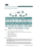
The equipment that I used in developing this lab included a Cisco 1604 router, and a Cisco 2610 router. The ISDN
simulator was a Teltone ISDN Demonstrator with two U interfaces. You will need to adjust the lab contents to fit your
ISDN simulator and/or routers as necessary. You MUST use an ISDN simulator or actual ISDN lines. There is no way
to configure ISDN using crossover cables or something similar. You can use any router with suitable ISDN interfaces,
but be aware of whether you have U interfaces or S/T interfaces. If you have S/T interfaces, then you will need an
NT1. Here is the basic starting point for cabling your equipment:
(The following information will vary depending upon your ISDN simulator or actual ISDN lines)
ISDN Information for Router1:
isdn switch-type basic-ni
isdn spid1 0835866101 8358661
isdn spid2 0835866301 8358663
ISDN Information for router2:
isdn switch-type basic-ni
isdn spid1 0835866201 8358662
isdn spid2 0835866401 8358664
Figure 1.
Configure Global Commands
1. Configure the ISDN switch type on each router
Before we begin, perform a write erase on each router to make sure that we are starting from scratch. After you enter
the write erase command, reload the router. When you receive a prompt to configure the router, enter ctrl-c and the
router will continue to boot up.
Once this is complete, check that no configuration exists by entering the write command followed by show
configuration. (Note: you can use show configuration instead of show run because you just saved the
configuration. This displays the current configuration faster than show run would.) You should not see any configured
IP addresses, routing statements, or ISDN configurations of any kind. Enter the IP addresses for the Ethernet
interfaces, no shut them, and use the no keep-alive command, if necessary, in case you don't have the Ethernet
interfaces plugged into a hub or switch.
Since we have no ISDN switch type configured, our first step should be to configure the ISDN switch type. We can
use the ? to help us find the correct syntax for our switch type, basic-ni1. We will need to use the isdn switch-type
global command on each router as follows:
Router1#
Router1#configure terminal (you can use conf t for short)
Router1(config)#
router1(config)#isdn switch-type ?
basic-1tr6 1TR6 switch type for Germany
basic-5ess AT&T 5ESS switch type for the U.S.
basic-dms100 Northern DMS-100 switch type
basic-net3 NET3 switch type for UK and Europe
basic-ni1 National ISDN-1 switch type
basic-nwnet3 NET3 switch type for Norway
basic-nznet3 NET3 switch type for New Zealand
CertificationZone Page 3 of 9
/?Issue=32&IssueDate=03-01-2001&CP= 11/06/01
basic-ts013 TS013 switch type for Australia
ntt NTT switch type for Japan
vn2 VN2 switch type for France
vn3 VN3 and VN4 switch types for France
router1(config)#isdn switch-type basic-ni1
router1(config)#^Z
router1#
00:23:38: %SYS-5-CONFIG_I: Configured from console by console
Now that we have configured the ISDN switch type, let's check it using the show isdn status command. If you
configured your routers correctly, you should see the following:
Router1#sh isdn stat
The current ISDN Switchtype = basic-ni1
ISDN BRI0 interface
Layer 1 Status:
DEACTIVATED
Layer 2 Status:
Layer 2 NOT Activated
Layer 3 Status:
0 Active Layer 3 Call(s)
Activated dsl 0 CCBs = 0
The Free Channel Mask: 0x80000003
Total Allocated ISDN CCBs = 0
2. No shut the BRI interfaces
No shut the BRI interfaces to make sure that each router is talking to the ISDN switch:
Router1(config)#int bri 0
Router1(config-if)#no shut
Router1(config-if)#^z
00:23:54: %LINK-3-UPDOWN: Interface BRI0:1, changed state to down
00:23:54: %LINK-3-UPDOWN: Interface BRI0:2, changed state to down
00:23:54: %LINK-3-UPDOWN: Interface BRI0, changed state to up
Although we are no shutting the physical interface, we are doing it only to check that the global command for the
ISDN switch type is correct. Once we no shut the BRI interface, we should see it come up. Check that the router is
communicating with the ISDN switch by examining the layer 1 status to make sure it is ACTIVE and checking the
layer 2 status to make sure it reads MULTIPLE FRAME ESTABLISHED. Here is what you will look see:
router#sh isdn stat
The current ISDN Switchtype = basic-ni1
ISDN BRI0 interface
Layer 1 Status:
ACTIVE
Layer 2 Status:
TEI = 70, State = MULTIPLE_FRAME_ESTABLISHED
Layer 3 Status:
No Active Layer 3 Call(s)
Activated dsl 0 CCBs = 0
Total Allocated ISDN CCBs = 0
We now know that we have correctly defined the ISDN switch type and that our router is talking to the ISDN switch on
the D channel. The next step is to configure the user password database so we can use this information for
authentication.
3. Configure the Username Password Database
The first step in configuring CHAP authentication is to set up local user databases on each router. What we need to
do is to enter the username for the opposite router and a common password using a global configuration command.
Since the instructions specified that we should use the usernames CCNA1 and CCNA2 instead of the router
hostnames we used in Lab 1, we need to configure the correct usernames. Don't forget that the passwords are case
sensitive. For example, on router1, we would enter the following:
Router1(config)#username CCNA2 password cisco
CertificationZone Page 4 of 9
/?Issue=32&IssueDate=03-01-2001&CP= 11/06/01
On router2, we would similarly enter:
Router2(config)#username CCNA1 password cisco
The next step in our configuration is to define interesting traffic.
4. Define Interesting Traffic Using Dialer Lists
A dialer-list is used to define "interesting traffic" (traffic for which you wish to bring up the ISDN connection). We
define a dialer-list in global configuration mode then apply the dialer-list using an interface configuration command
dialer-group. When I am configuring ISDN DDR, I like to first define my dialer lists very broadly using IP until I have
all features working, such as call setup and teardown, authentication, callback, etc. Once I have basic features
working correctly, then I will make the dialer list more selective, if necessary, using an access-list. Here is an example
that shows how traffic can be defined as interesting using a broad dialer list:
Router1(config)#dialer-list 1 protocol ?
Appletalk Appletalk
Bridge Bridging
Clns OSI Connectionless Area Services
Clns_es CLNS End System
Clns_is CLNS Intermediate System
Decnet DECnet
Decnet DECnet node
Decnet_router-L1 DECnet router L1
Decnet_router-L2 DECnet router L2
Ip IP
Ipx Novell IPX
Llc2 LLC2
Vines Banyan Vines
Xns XNS
Using the above syntax, the first dialer list I like to configure is
Router1(config)#dialer-list 1 protocol ip permit
We will cover applying the dialer-list later when we cover the dialer interface commands. For now, our next task is to
configure our routing protocol, RIP Version 2.
5. Configure the Rip version 2 routing protocol
Configuring RIP is very simple, but we need to be aware of the differences between Version 1 and Version 2. Can you
remember them off the top of your head? The two major differences are 1) RIP version 1 is classful whereas RIP
version 2 is not, and 2) RIP version 2 supports VLSM. Another difference is that RIP version 2 supports route
authentication. We will not cover route authentication here, just be aware that it exists and should not be confused
with PPP authentication.
To configure RIP Version 2, all we have to do is enable the RIP routing process, define the participating networks,
and specify version 2. This will be done on each router as follows:
Router2(config)#router rip
Router2(config)#network 10.0.0.0
Router2(config)#network 172.19.0.0
Router2(config)#version 2
We can check that RIP version 2 is enabled using the show ip protocols command on each router. Now that we
have completed the global configuration commands, our next step is to configure the physical BRI interface. For our
final step, we will create and configure logical dialer interfaces.
Configure Physical Interface Commands
1. Enable encapsulation PPP
With dialer profiles, we must specify encapsulation PPP on both the physical BRI interface and the logical dialer
CertificationZone Page 5 of 9
/?Issue=32&IssueDate=03-01-2001&CP= 11/06/01
interface. Here is an example:
Router2(config)#interface bri 0
Router2(config-if)#encapsulation ppp
Since we are going to use PPP CHAP authentication, we must configure it, also, on both the physical and the logical
interfaces.
2. Specify ppp authentication chap
Router2(config)#interface bri 0
Router2(config-if)#ppp authentication chap
Although we are going to use dialer profiles, we still need to configure SPIDs under the physical BRI interface.
3. Configure SPIDs (If Necessary)
The example below shows how SPIDs are entered as well as how we can check that they are configured correctly.
Router2(config-if)#isdn spid1 ?
WORD spid1 string
Router2(config-if)#isdn spid1 0835866201 ?
WORD local directory number
<cr>
router2(config-if)#isdn spid1 0835866201 8358662
router2(config-if)#isdn spid2 0835866401 8358664
Now, let's look at an example where the SPIDs have been configured correctly, sent, and are valid. This will not occur
unless the router's configuration matches the configuration of the ISDN switch exactly.
Router2#sh isdn stat
The current ISDN Switchtype = basic-ni1
ISDN BRI0 interface
Layer 1 Status:
ACTIVE
Layer 2 Status:
TEI = 76, State = MULTIPLE_FRAME_ESTABLISHED
TEI = 77, State = MULTIPLE_FRAME_ESTABLISHED
Spid Status:
spid1 configured, spid1 sent, spid1 valid
spid2 configured, spid2 sent, spid2 valid
Layer 3 Status:
0 Active Layer 3 Call(s)
Activated dsl 0 CCBs = 0
4. Assign the physical BRI interface to a dialer pool
Since we are going to configure dialer profiles, our configuration differs at this point from legacy DDR. Because we
can create many logical dialer interfaces, but have a fixed number of physical BRI interfaces, we need a method to
assign the physical interface to the desired logical dialer interface. The reasons for this become clearer when you
think of a situation where you have only two physical BRI interfaces, but need to use four logical dialer interfaces to
connect other routers. The first BRI interface may be in use by one of the logical dialer interfaces when we need to
place an additional call. By defining both physical BRI interfaces as members of the same dialer pool, the next
available physical BRI interface will be dynamically bound to the logical dialer interface at the time of the call.
Before we configure the physical BRI interface for dialer profiles, we first need to remove all legacy DDR commands,
including dialer map statements, dialer group statements, and network layer addresses. This step should not be
necessary for this lab because we write erased the routers at the beginning of the lab. Here is an example of how we
assign the physical interface to a dialer pool. A physical interface can be assigned to multiple dialer pools, but a
logical dialer interface can only be assigned to a single dialer pool.
Router1(config)#interface bri 0
Router1(config-if)#dialer pool-member 1
Now that we have assigned the physical BRI interface to a dialer pool, we have completed the interface commands
CertificationZone Page 6 of 9
/?Issue=32&IssueDate=03-01-2001&CP= 11/06/01
for the physical BRI interface. The next step is to create a logical dialer interface.
Configure Logical Dialer Interface Commands
So far, the global and physical BRI interface commands have been relatively simple. The most complicated portion of
the overall configuration consists of the creation of the logical dialer interface and the more extensive commands
applied to it. Here is an overview of the remaining steps.
First, we need to create the logical dialer interface. Next, we need to associate a dialer pool with the dialer interface
using the dialer pool number command, where number is the same number previously used with the dialer pool-
member command. Next, we add a dialer-group statement to define interesting traffic and a dialer string to call.
Since we want to use alternate CHAP hostnames, we need to configure them using the ppp chap hostname
command. Finally, we add a dialer remote-name command to enable creation of a dynamic dialer map to the remote
router. We also need to repeat the encapsulation ppp and ppp authentication chap commands we used on the
physical BRI interface.
1. Create the logical dialer interface
To configure the logical dialer interface, we first need to create a logical dialer interface in the same way we create
other logical interfaces such as loopback interfaces.
Router1(config)#interface dialer 0
2. Assign an IP address to the dialer interface
Router1(config-if)#ip address 172.19.1.6 255.255.255.252
3. Enable PPP Encapsulation
Router1(config-if)#encapsulation ppp
4. Configure the Dialer Interface for PPP Authentication CHAP
To configure PPP CHAP authentication, we first need to use the same command we used under the physical BRI
interface. We then need to use a new command, ppp chap hostname, to specify the hostname we want to use for
authentication. This can be totally different from the router's own hostname and is, in our case, CCNA1 or CCNA2.
Here is an example:
Router1(config-if)#ppp authentication chap
Router1(config-if)#ppp chap hostname CCNA1
Next, we need to tell the logical dialer interface what dialer-list to use to define interesting traffic.
5. Apply the dialer-list to define interesting traffic
Since we are using dialer profiles, we need to apply the dialer list we created previously to the dialer interface, rather
then the physical BRI interface, using the dialer-group command:
Router1(config)#interface dialer0
Router1(config-if)#dialer-group 1
6. Specify which dialer-pool to use
Next, we need to tell the logical dialer interface which dialer pool to use. Although we can only specify a single dialer
pool to use under the logical dialer interface, the dialer pool can contain multiple physical BRI interfaces.
Router1(config)#interface dialer 0
Router1(config-if)#dialer pool 1
CertificationZone Page 7 of 9
/?Issue=32&IssueDate=03-01-2001&CP= 11/06/01
7. Configure the dialer remote name and string
Dialer profiles use dynamic dialer maps, which are created automatically at the time a call is placed, to dial the
remote router. We use a combination of a dialer string and dialer remote name to enable the creation of the dynamic
dialer maps.
Router1(config)#interface dialer0
Router1(config-if)#dialer remote-name router2
Router1(config-if)#dialer string 8358662
8. Check our work
At this point, our configuration is complete. We can now check our work by pinging from router1 to router2 and vice
versa.
router1#ping 172.19.1.5
Type escape sequence to abort.
Sending 5, 100-byte ICMP Echos to 172.19.1.5, timeout is 2 seconds:
!!!!!
Success rate is 100 percent (5/5), round-trip min/avg/max = 1/2/4 ms
SOLUTION REVEALED
Router1's Final Configuration
version 12.0
!
hostname router1
!
username CCNA2 password 0 cisco
!
ip subnet-zero
!
isdn switch-type basic-ni
!
interface Ethernet0/0
ip address 10.10.11.1 255.255.255.0
no ip directed-broadcast
!
interface Serial0/0
no ip address
shutdown
!
interface BRI0/0
encapsulation ppp
isdn switch-type basic-ni
isdn spid1 0835866101 8358661
isdn spid2 0835866301 8358663
ppp authentication chap
dialer pool-member 1
!
interface dialer 0
ip address 172.19.1.6 255.255.255.252
encapsulation ppp
dialer remote-name router2
dialer string 8358662
dialer pool 1
dialer-group 1
ppp authentication chap
ppp chap hostname CCNA1
!
ip classless
!
router rip
version 2
network 10.0.0.0
CertificationZone Page 8 of 9
/?Issue=32&IssueDate=03-01-2001&CP= 11/06/01
network 172.19.0.0
!
dialer-list 1 protocol ip permit
!
line con 0
transport input none
line aux 0
line vty 0 4
login
!
no scheduler allocate
end
router1#sh ip route
Codes: C - connected, S - static, I - IGRP, R - RIP, M - mobile, B - BGP
D - EIGRP, EX - EIGRP external, O - OSPF, IA - OSPF inter area
E1 - OSPF external type 1, E2 - OSPF external type 2, E - EGP
i - IS-IS, L1 - IS-IS level-1, L2 - IS-IS level-2, * - candidate default
U - per-user static route
Gateway of last resort is not set
10.0.0.0/8 is subnetted, 1 subnets
C 10.10.11.1 is directly connected, Ethernet0
R 10.10.12.0/24 [120/2] via 172.19.1.5, 00:02:46, BRI0/0
172.19.0.0/16 is subnetted, 1 subnets
C 172.19.1.4 is directly connected, BRI0/0
Router2's Final Configuration
version 12.0
!
hostname router2
!
username router1 password 0 cisco
!
ip subnet-zero
!
isdn switch-type basic-ni
!
interface Ethernet0/0
ip address 10.10.12.1 255.255.255.0
no ip directed-broadcast
!
interface Serial0/0
no ip address
shutdown
!
interface BRI0/0
encapsulation ppp
isdn switch-type basic-ni
isdn spid1 0835866001 8358660
isdn spid2 0835866201 8358662
ppp authentication chap
dialer pool-member 1
!
interface dialer 0
ip address 172.19.1.5 255.255.255.252
encapsulation ppp
dialer remote-name router1
dialer string 8358660
dialer pool 1
dialer-group 1
ppp authentication chap
ppp chap hostname CCNA2
!
ip classless
!
router rip
version 2
network 10.0.0.0
network 172.19.0.0
!
dialer-list 1 protocol ip permit
CertificationZone Page 9 of 9
/?Issue=32&IssueDate=03-01-2001&CP= 11/06/01
!
line con 0
transport input none
line aux 0
line vty 0 4
login
!
no scheduler allocate
end
Router2#sh ip route
Codes: C - connected, S - static, I - IGRP, R - RIP, M - mobile, B - BGP
D - EIGRP, EX - EIGRP external, O - OSPF, IA - OSPF inter area
E1 - OSPF external type 1, E2 - OSPF external type 2, E - EGP
i - IS-IS, L1 - IS-IS level-1, L2 - IS-IS level-2, * - candidate default
U - per-user static route
Gateway of last resort is not set
10.0.0.0/8 is subnetted, 1 subnets
C 10.10.12.1 is directly connected, Ethernet0
R 10.10.11.0/24 [120/2] via 172.19.1.6, 00:02:46, BRI0
172.19.0.0/16 is subnetted, 1 subnets
C 172.19.1.4 is directly connected, BRI0
[NA-DDR-LS2-F03]
[2001-02-23-01]
Copyright © 2001 Genium Publishing Corporation