Tài liệu Link Efficiency Mechanisms ppt
Bạn đang xem bản rút gọn của tài liệu. Xem và tải ngay bản đầy đủ của tài liệu tại đây (3.24 MB, 66 trang )
6
Link Efficiency
Mechanisms
Overview
The module describes one approach to handling congested links; compression. It
discusses link efficiency mechanisms that either compress the payload of packets
(Stacker and Predictor) or reduce packet overhead by compressing their headers
(TCP and RTP header compression). It also discusses two different layer-2 link
fragmentation mechanisms (PPP Multilink and Frame Relay Fragmentation).
Objectives
Upon completion of this module, you will be able to perform the following tasks:
n Describe and configure Stacker payload compression
n Describe and configure Predictor payload compression
n Describe and configure TCP header compression
n Describe and configure RTP header compression
n Describe and configure PPP Multilink with interleaving
n Describe and configure Frame Relay Fragmentation
6-2 IP QoS Link Efficiency Mechanisms Copyright 2001, Cisco Systems, Inc.
Payload Compression
Overview
This lesson describes two payload compression mechanisms. It describes the
Stacker and Predictor mechanisms that can be used to reduce the size of data in
packets or frames.
Objectives
Upon completion of this lesson, you will be able to perform the following tasks:
n Describe and configure Stacker compression
n Describe and configure Predictor compression
n Monitor and troubleshoot compression
Copyright 2001, Cisco Systems, Inc. IP QoS Link Efficiency Mechanisms 6-3
© 2001, Cisco Systems, Inc. IP QoS Link Efficiency Mechanisms -5
Payload Compression
Payload Compression
QoS does not create bandwidth. Payload
compression does.
Payload compression uses a
compression algorithm to squeeze the
payload of layer-2 frames
Payload compression increases
perceived throughput and decreases
perceived latency
While many mechanisms exist for optimizing throughput and reducing delay in
network traffic within the QoS portfolio, QoS does not create bandwidth. QoS
optimizes the use of existing resources, and enables the differentiation of traffic
according to the operator policy.
Payload compression does create additional bandwidth, because it squeezes packet
payloads, and therefore increases the amount of data that can be sent through a
transmission resource in a given time period. Payload compression is mostly
performed on layer-2 frames and therefore compresses the entire layer-3 packet.
Note that IP PCP (Payload Compression Protocol) is a fairly new technique for
compressing payloads on layer 3, and can handle out-of-order data. The IP PCP
compression method is not discusses in this lesson.
As compression squeezes payloads, it both increases the perceived throughput, and
decreases perceived latency in transmission, because smaller, packets (with
compressed payloads) take less time to transmit (than the larger, uncompressed
packets).
6-4 IP QoS Link Efficiency Mechanisms Copyright 2001, Cisco Systems, Inc.
© 2001, Cisco Systems, Inc. IP QoS Link Efficiency Mechanisms -6
Compression Building Blocks
Compression Building Blocks
Compression reduces the size of the frame payload
Entire IP packet is compressed
Compression adds delay due to its complexity
Serialization delay is reduced, overall latency might be
reduced
Compression
Algorithm
Forwarder
Output
Queue
FH IP FH cIP
Compression is a
CPU-intensive task
It adds to the
overall delay
experienced by IP
packets.
Packets reduced in
size take less time
to transmit.
More packets can
be transmitted.
The figure shows a basic block diagram of a compression method. When a router
forwards a packet, it is subjected to the layer-2 compression method after it has
been encapsulated at the output. The compression method squeezes the payload of
the layer-2 frame (the entire layer-3 packet), and transmits the packet on the
interface. Layer-2 compression requires serialization of packet delivery, which
means that packets must be received by the remote layer-2 station in the same
order as they were sent.
Compression is a CPU-intensive task and can add per-packet delay due to the
application of the compression method to each frame. The transmission
(serialization) delay, however, is reduced, because the resulting frame is smaller.
Depending on the complexity of the payload compression algorithm, overall latency
might be reduced, especially on low-speed links.
Copyright 2001, Cisco Systems, Inc. IP QoS Link Efficiency Mechanisms 6-5
© 2001, Cisco Systems, Inc. IP QoS Link Efficiency Mechanisms -7
COMPRESSION
COMPRESSION
NO COMPRESSION
NO COMPRESSION
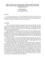
Compression Results
Compression Results
Compression increases throughput
Compressions may increase delay
Link bandwidth
256 kbps
Link bandwidth
256 kbps
Throughput
256 kbps
Delay=1 ms Delay=8 ms
Delay=10 ms Delay=4 ms
HARDWARE COMPRESSION
HARDWARE COMPRESSION
Link bandwidth
256 kbps
Delay=2 ms Delay=4 ms Total Delay=6 ms
Total Delay=14ms
Total Delay=9 ms
Throughput
500 kbps
Throughput
500 kbps
The figure compares three throughput/latency scenarios on a point-to-point link. If
no compression is used, the perceived throughput is limited by the link bandwidth,
and the average delay is influenced only by the forwarding/buffering delay and the
serialization (transmission) delay.
If compression is enabled, the packet latency between the two hops is a function of
forwarding delay, compression delay, and transmission delay. Even if the
transmission delay is now shorter, the compression/decompression delay may
increase the overall latency between the two hops. Throughput is generally
increased and is limited by the effectiveness of the compression algorithm.
If hardware-assisted compression is used, the compression/decompression delays
may become insignificant compared to transmission and forwarding delays, and
overall latency may decrease. Throughput is again limited by the effectiveness of
the compression method and may be significantly higher than the link bandwidth
limit.
6-6 IP QoS Link Efficiency Mechanisms Copyright 2001, Cisco Systems, Inc.
© 2001, Cisco Systems, Inc. IP QoS Link Efficiency Mechanisms -8
Compression Algorithms
Compression Algorithms
Cisco routers support the following
compression algorithms:
• STAC or Stacker (STAC Electronics or Hi/fn,
Inc.)
• MPPC (Microsoft Point-to-point
Compression)
• Predictor (public domain algorithm)
These algorithms differ in compression
capabilities, CPU and memory utilization
Cisco IOS supports three different compression algorithms used in layer-2
compression: STAC (or Stacker), Microsoft Point-to-Point Compression (MPPC),
and predictor. These algorithms differ vastly in their compression efficiency, and in
utilization of router resources.
Copyright 2001, Cisco Systems, Inc. IP QoS Link Efficiency Mechanisms 6-7
© 2001, Cisco Systems, Inc. IP QoS Link Efficiency Mechanisms -9
Stacker and MPPC Compression
Stacker and MPPC Compression
Stacker or STAC is a compression algorithm
developed by STAC Electronics
Stacker uses the LZ (Lempel-Ziv) algorithm that
searches for redundant strings and replaces
them with short tokens
It builds a dictionary where token values are
mapped to these strings
MPPC is developed by Microsoft and also uses
the LZ algorithm
The STAC (or Stacker) algorithm is based on the well-known LZ (Lempel-Ziv)
compression algorithm. The LZ (sometimes also called LZW) algorithm searches
the byte stream for redundant strings, and replaces them with shorter dictionary
tokens. The dictionary is built in real time, and there is no need to exchange the
dictionary between the compression peers, because the dictionary is reconstructed
from the data received by the remote peer. The MPPC method also uses the same
LZ algorithm. The STAC and MPPC algorithms yield very good compression
results, but are CPU-intensive.
6-8 IP QoS Link Efficiency Mechanisms Copyright 2001, Cisco Systems, Inc.
© 2001, Cisco Systems, Inc. IP QoS Link Efficiency Mechanisms-10
Predictor Compression
Predictor Compression
Predictor is a public domain
compression algorithm
Predictor uses a hashed sequence of
characters as an index into the
compression dictionary
The entry in the dictionary is compared
to the next sequence of characters
The predictor is a simple, very fast, and CPU-friendly algorithm, but this algorithm
yields a lower compression ratio. It is based on predicting the next byte-sequence
in the stream based on a simple dictionary, which is rebuilt from the source or the
compressed data without the need to exchange a dictionary between the peers.
Copyright 2001, Cisco Systems, Inc. IP QoS Link Efficiency Mechanisms 6-9
© 2001, Cisco Systems, Inc. IP QoS Link Efficiency Mechanisms-11
Stacker/MPPC vs. Predictor
Stacker/MPPC vs. Predictor
Stacker and MPPC are very CPU-intensive
• Good average compression ratio
• Slower
• Produces more delay
• Should be used on slower links
• Stacker has more tuning capabilities
Predictor requires more memory
• Less efficient than Stacker or MPPC
• Faster, uses less CPU time
• Produces less delay
• Can be used on faster links
The STAC, MPPC, and predictor algorithms are usually used to perform layer-2
payload compression on point-to-point links between Cisco IOS routers. The
STAC and MPPC methods are CPU-intensive. However these methods yield very
good compression rates on the average, produce more compression/decompression
delay in the router, and should be used on slower links if software compression is
used.
Predictor is a leaner and simpler algorithm, which can be deployed on faster links
with software compression, and which introduces less delay in the packet path.
However, predictor yields considerably lower compression ratios compared to the
STAC algorithm.
6-10 IP QoS Link Efficiency Mechanisms Copyright 2001, Cisco Systems, Inc.
© 2001, Cisco Systems, Inc. IP QoS Link Efficiency Mechanisms-12
Compression and Layer-2
Encapsulation
Compression and Layer-2
Encapsulation
PPP
Frame Relay
HDLC
LAPB
X.25
STAC Predictor MPPC
ü
ü
*
*
ü
ü
ü
ü
ü
ü
*
*
O
O
O
O
üü OO OO
ü
ü
ü
ü
O
O
ü
ü
O
O
O
O
* PPP and Frame Relay Stacker is also supported by
hardware compression modules
The figure shows a comparison of different compression methods used by Cisco
IOS to perform layer-2 payload compression. The STAC method is the most
versatile, because it runs on any supported point-to-point layer-2 encapsulation.
Predictor only supports PPP and LAPB, while MPPC only runs within PPP.
Hardware-accelerated compression substantially increases compression throughput
for CPU-intensive compression methods (such as STAC and MPPC, both based
on the LZ algorithm) and is recommended when used on high-bandwidth links.
Copyright 2001, Cisco Systems, Inc. IP QoS Link Efficiency Mechanisms 6-11
© 2001, Cisco Systems, Inc. IP QoS Link Efficiency Mechanisms-13
Performance
Performance
Compression performance depends on
the following factors:
• Router platform (CPU power)
• Compression algorithm (Stacker, MPPC or
Predictor)
• Hardware compression support
Real-life compression performance depends on many factors, the most important
being:
n Router CPU performance, if compression is performed in software. The router
runs the compression algorithm for each packet on an interface, configured for
compression.
n The compression algorithm because there are large differences in the
performance of the algorithm itself. Generally, CPU-intensive algorithms
produce better compression ratios.
n Hardware compression support offloads the task of compression from the
CPU, which decreases forwarding latency and frees the CPU to perform
other tasks.
n Data compressibility, which influences both the compression ratio and
sometimes the performance of the algorithm itself.
On average, Stacker and MPPC can yield up to 50% reduction in data size (a
compression ratio of 2), when used on real network traffic. Predictor can
theoretically achieve such a rate, if network traffic includes mostly predictive text
data. In most networks, predictor compression ratio is much lower than Stacker’s,
and usually in the 30-40% range of data size reduction (that is, compression ratios
less than 1.8).
6-12 IP QoS Link Efficiency Mechanisms Copyright 2001, Cisco Systems, Inc.
© 2001, Cisco Systems, Inc. IP QoS Link Efficiency Mechanisms-14
Configuring Stacker
Configuring Stacker
Interface configuration steps:
• Select one of the supported layer-2
encapsulations (PPP, F/R, HDLC, LAPB or
X.25)
• Enable Stacker compression
• Optionally select the ratio, force software
based compression or enable distributed
compression
Monitor compression
Stacker (STAC) compression is configured on interfaces with the appropriate
supported encapsulation. The STAC method can be tuned, and software or
hardware compression can be selected. After STAC has been enabled on an
interface, Cisco IOS provides a means to monitor the compression ratios in real
time.
Copyright 2001, Cisco Systems, Inc. IP QoS Link Efficiency Mechanisms 6-13
© 2001, Cisco Systems, Inc. IP QoS Link Efficiency Mechanisms-15
Configuring Stacker with PPP
Encapsulation
Configuring Stacker with PPP
Encapsulation
compress stac
compress stac
Router(config-if)#
• Enables STAC with default parameters
compress stac distributed
compress stac distributed
Router(config-if)#
• Offloads compression to a VIP
• Supported on VIP2-40 or newer
compress stac ratio {high | low | medium}
compress stac ratio {high | low | medium}
Router(config-if)#
• Balance throughput with delay
• Low compression ratio is the default
The compress stac command enables STAC compression on an interface with
supported encapsulation.
STAC can also run distributed on the VIP processor.
The compress stac ratio command tunes STAC so that the compression ratio is
traded for delay. For example, selecting a low compression ratio produces less
CPU usage, while the high compression ratio performs better compression, but
increases the CPU load and adds delay, which may decrease throughput. The
recommended ratio depends on the type of network traffic and its sensitivity to
delay. The rule of thumb is to start with the default low ratio, and try to increase
the ratio and measure throughput. If observed compression ratios increase (as
shown by the show compression command), but throughput actually decreases,
the configured ratio should be lowered again.
6-14 IP QoS Link Efficiency Mechanisms Copyright 2001, Cisco Systems, Inc.
© 2001, Cisco Systems, Inc. IP QoS Link Efficiency Mechanisms-16
Configuring Stacker with Frame
Relay Encapsulation
Configuring Stacker with Frame
Relay Encapsulation
frame-relay payload-compression FRF9 stac
frame-relay payload-compression FRF9 stac
Router(config-if)#
• Enables STAC with default parameters
frame-relay payload-compression FRF9 stac distributed
frame-relay payload-compression FRF9 stac distributed
Router(config-if)#
• Offloads compression to a VIP
• Supported on VIP2-40 or newer
frame-relay payload-compression FRF9 stac ratio {high | low}
frame-relay payload-compression FRF9 stac ratio {high | low}
Router(config-if)#
• Balance throughput with delay
• Low compression ratio is the default
Cisco IOS supports the native Frame Relay compression protocol according to the
FRF.9 standard. The compression method used is equivalent to STAC
compression. Also, the commands required to configure Frame Relay STAC
compression are analogous to the command used to configure STAC with other
supported encapsulations. This command should be used when using the default
Frame Relay encapsulation over Frame Relay networks.
Copyright 2001, Cisco Systems, Inc. IP QoS Link Efficiency Mechanisms 6-15
© 2001, Cisco Systems, Inc. IP QoS Link Efficiency Mechanisms-17
Configuring Predictor or MPPC
Configuring Predictor or MPPC
compress predictor
compress predictor
Router(config-if)#
• Enables Predictor compression
compress mppc [ignore-pfc]
compress mppc [ignore-pfc]
Router(config-if)#
• Enables MPPC compression
• Use the ignore-pfc option to ignore the protocol
number negotiation
The compress predictor command configures predictor compression. No tuning
parameters are available for this command.
The compress mppc command configures MPPC compression, and is used
mainly with Windows clients and when running a layer-2 tunneling session (for
example, the Point-to-Point Tunneling Protocol (PPTP). The ignore-pfc keyword
instructs the router to ignore the protocol field compression flag negotiated by
LCP. For example, the uncompressed standard protocol field value for IP is
0x0021 and 0x21 when compression is enabled. When the ignore-pfc option is
enabled, the router will continue to use the uncompressed value (0x0021). Using
the ignore-pfc option is helpful for some asynchronous driver devices that use an
uncompressed protocol field (0x0021), even though the pfc is negotiated between
peers. If protocol rejects are displayed when the debug ppp negotiation command
is enabled, setting the ignore-pfc option may remedy the problem.
6-16 IP QoS Link Efficiency Mechanisms Copyright 2001, Cisco Systems, Inc.
© 2001, Cisco Systems, Inc. IP QoS Link Efficiency Mechanisms-18
Hardware Compression
Hardware Compression
Hardware compression is available using
the following modules:
• Compression Advanced Interface Module (CAIM)
is a daughter-board module for Cisco 2600 series
routers
• Compression Service Adapter (CSA) module for
Cisco 7x00 series routers
• Compression Network Module (NM-COMPR2) for
Cisco 3620 and Cisco 3640 series routers
• AIM-COMPR4 is a daughter-board compression
module for Cisco 3660 series routers
There are a number of hardware compression modules and daughter boards
available for use in Cisco routers.
n The Compression Advanced Interface Module (CAIM) is a daughter board
that is placed in the AIM motherboard slot on Cisco 2600-series routers. It
does not occupy any network interface slots, and accelerates the STAC and
MPPC compression methods.
n The Compression Service Adapter (CSA) is a port adapter for the Cisco 7x00
series routers. The CSA offloads the compression task from the main CPU or
the VIP2 (using distributed compression). When used in the Cisco 7200-series
router, the CSA can offload compression at any interface. If used on the
VIP2, it offloads compression at the adjacent port adapter on the same VIP
only.
n The Compression Network Module is a network module for the Cisco 3600-
series routers. The Compression Network Module occupies a network module
slot in the router, and can offload compression at any router interface.
n The AIM-COMPR4 is a hardware-compression daughter board used in the
Cisco 3660 router. The AIM-COMPR4 integrates with the router motherboard
and does not occupy any network module slots in the chassis.
Copyright 2001, Cisco Systems, Inc. IP QoS Link Efficiency Mechanisms 6-17
© 2001, Cisco Systems, Inc. IP QoS Link Efficiency Mechanisms-19
Configuration Example
Configuration Example
interface Serial1/0
encapsulation ppp
compress stac
!
interface Serial1/1
encapsulation ppp
compress stac caim 0
!
interface Serial1/2
encapsulation ppp
compress predictor
!
interface Serial1/2
encapsulation frame-relay
frame-relay map ip 1.1.1.1 102 broadcast ietf payload-compress frf9 stac
!
interface Serial1/2.1 point-to-point
frame-relay interface-dlci 101 ietf
frame-relay payload-comp FRF9 stac
!
Software compression using the
STAC algorithm
Hardware compression using the
STAC algorithm on the CAIM
module (Cisco 2600 routers)
Software compression using
the STAC algorithm
Software compression using the
Predictor algorithm
The figure shows configuration examples that specify different compression
configurations.
In the example, the Serial1/0 interface uses software compression (this setting may
automatically use hardware compression on high-end series).
The Serial1/1 interface performs compression with the assistance of the CAIM (in
a Cisco 2600-series router).
Interfaces Serial1/2 and its Serial 1/2.1 sub-interface both use software STAC
compression on the frame-relay level.
6-18 IP QoS Link Efficiency Mechanisms Copyright 2001, Cisco Systems, Inc.
© 2001, Cisco Systems, Inc. IP QoS Link Efficiency Mechanisms-20
Monitoring Compression
Monitoring Compression
Router#show compression
Serial5/1/0
Software compression enabled
uncompressed bytes xmt/rcv 21339/21339
compressed bytes xmt/rcv 0/0
1 min avg ratio xmt/rcv 2.110/2.110
5 min avg ratio xmt/rcv 2.143/2.143
10 min avg ratio xmt/rcv 2.143/2.143
no bufs xmt 0 no bufs rcv 0
resyncs 0
Additional Stacker Stats:
Transmit bytes: Uncompressed = 0 Compressed = 9109
Received bytes: Compressed = 9953 Uncompressed = 0
show compression
show compression
Router#
• Displays compression statistics
The show compression command displays per-interface compression statistics.
The ratio shown in the output indicates the compression ratio (the ratio of
uncompressed over the actual compressed byte stream size) on the input and the
output of an interface.
Copyright 2001, Cisco Systems, Inc. IP QoS Link Efficiency Mechanisms 6-19
Summary
n Stacker and MPPC payload compression methods yield better compression
ratios, is more CPU-intensive, and may introduce additional delay
n The predictor payload compression method is faster, can be used in higher-
bandwidth scenarios, but generally yields lower average compression ratios
Lesson Review
1. What is the purpose of using payload compression?
2. List the payload compression algorithms than can be used.
3. What are some of the benefits and drawbacks of Stacker?
4. What are some of the benefits and drawbacks of Predictor?
6-20 IP QoS Link Efficiency Mechanisms Copyright 2001, Cisco Systems, Inc.
Header Compression
Overview
This lesson describes the mechanisms that are used to reduce overhead on slow
links by compressing IP and TCP headers in TCP header compression, or IP,
UDP and RTP headers in RTP header compression.
Objectives
Upon completion of this lesson, you will be able to perform the following tasks:
n Describe and configure TCP header compression
n Monitor and troubleshoot TCP header compression
n Describe and configure RTP header compression
n Monitor and troubleshoot RTP header compression
Copyright 2001, Cisco Systems, Inc. IP QoS Link Efficiency Mechanisms 6-21
© 2001, Cisco Systems, Inc. IP QoS Link Efficiency Mechanisms-26
Header Compression
Header Compression
Header compression reduces the overhead by
compressing packet and segment headers
TCP Header compression compresses the IP
and TCP headers
RTP header compression compresses the IP,
UDP and RTP headers
Header compression is especially effective on
slow links with interactive traffic or delay
sensitive traffic (many short packets)
All compression methods are based on eliminating redundancy when sending the
same or similar data over a transmission medium. One piece of data, which is often
repeated, is the protocol header. In a flow, the header information of packets in the
same flow does not change much over the lifetime of that flow. Therefore, most of
header information could be sent only at the beginning of the session, stored in a
dictionary, and then referenced in later packets by a short dictionary index.
Two methods were standardized by the IETF (Internet Engineering Task Force)
for use with IP protocols:
n TCP header compression (also known as the Van Jacobson or VJ header
compression) is used to compress the packet TCP headers over slow links,
thus considerably improving the interactive application performance.
n RTP header compression is used to compress UDP and RTP headers, thus
lowering the delay for transporting real-time data, such as voice and video over
slower links.
6-22 IP QoS Link Efficiency Mechanisms Copyright 2001, Cisco Systems, Inc.
© 2001, Cisco Systems, Inc. IP QoS Link Efficiency Mechanisms-26
Header Compression Basics
Header Compression Basics
Compression is performed by eliminating
static or predicable header information
Session indices are used instead
Only changing parameters in headers are
still sent
Header compression is enabled on a link-
by-link basis
Header compression methods work by not transmitting repeated information in
packet headers throughout a session. For a TCP session, such parameters are the
IP header and the TCP port numbers. The two peers on a point-to-point layer-2
connection (such as a dial-up link) agree on session indices, which index a
dictionary of packet headers. The dictionary is built at the start of every session,
and is used for all subsequent (non-initial) packets. Only changing (non-constant)
parameters in the headers are actually sent with the session index.
It is important to note that header compression is performed on a link-by-link basis.
Header compression cannot be performed across multiple routers, because routers
need full Layer-3 header information to be able to route packets to the next hop.
Copyright 2001, Cisco Systems, Inc. IP QoS Link Efficiency Mechanisms 6-23
© 2001, Cisco Systems, Inc. IP QoS Link Efficiency Mechanisms-28
Header Compression
Building Blocks
Header Compression
Building Blocks
Compression reduces the size of packet
headers
The payload is not changed
Header
Compression
Algorithm
Forwarder
Output
Queue
FH IP FH cH
The header
compression
algorithm keeps
track of flows and
static parameters
in headers
IP and higher-layer
headers are
compressed
L4 (L5) payloadpayload
The figure shows a block diagram of a header compression method. The header
compression algorithm tracks active transport-layer connections over an interface.
After the packet has been forwarded, the header compression algorithm
compresses the layer-3 and layer-4 headers within the frame, and replaces them
with a session index from the session dictionary (table). The packet is then sent to
the output queue, and transmitted to the remote peer. When the remote peer
receives the packet, the header is decompressed using the local session table, and
passed to the forwarding process.
6-24 IP QoS Link Efficiency Mechanisms Copyright 2001, Cisco Systems, Inc.
© 2001, Cisco Systems, Inc. IP QoS Link Efficiency Mechanisms-29
COMPRESSION
COMPRESSION
NO COMPRESSION
NO COMPRESSION
Header Compression Results
Header Compression Results
Header compression increases throughput
Header compressions reduces delay
Link bandwidth
64 kbps
Link bandwidth
64 kbps
Throughput
64 kbps
Throughput
100 kbps
Delay=1 ms
Delay=8 ms
Delay=2 ms
Delay=4 ms
By compressing the header, the layer-2 frame gets smaller and therefore more
data is sent through a channel in a given time period. Also, the packet transmission
time is smaller; therefore header compression both increases the throughput and
reduces the overall delay of a transmission line.
Copyright 2001, Cisco Systems, Inc. IP QoS Link Efficiency Mechanisms 6-25
© 2001, Cisco Systems, Inc. IP QoS Link Efficiency Mechanisms-30
Header Compression Algorithms
Header Compression Algorithms
TCP Header Compression (RFC 1144)
• Used to reduce the overhead of TCP
segments
• Most effective on slow links with a lot of
TCP sessions with small payloads (for
example, Telnet)
RTP Header Compression (RFC 1889)
• Used to reduce delay and increase
throughput for Real Time Protocol (RTP)
• Improves voice quality
• Most effective on slow links
The two header compression methods available in Cisco IOS are the TCP header
compression (standardized by RFC 1144), and the RTP header compression
(standardized by RFC 1889). TCP header compression is usually used to improve
the interactive session response over low-speed links, where layer-3 and layer-4
headers represent a significant portion of the layer-2 frame. RTP header
compression is used mostly on slow links, to reduce delay and increase throughput
of an RTP-based application (usually voice traffic).