Tài liệu ime Control of a Three Phase 4 Wire PWM Inverter with Variable DC Link Voltage and Battery Storage for PV Application doc
Bạn đang xem bản rút gọn của tài liệu. Xem và tải ngay bản đầy đủ của tài liệu tại đây (311.66 KB, 9 trang )
T
p
w
a
c
c
P
c
v
l
v
N
a
The
D
Wir
e
T
he discret
e
simultaneo
u
p
hotovoltai
c
w
hole syste
m
a
nd three p
h
c
ontrolled i
n
(
MPP) whe
n
c
onverter is
P
WM inver
t
system is fi
r
c
ontrol met
h
v
oltage of t
h
l
oad unbala
n
v
erify the v
a
N
owadays
m
a
s well as i
n
D
iscr
e
e
PW
M
Volta
Dipl. Ing
.
e
time contr
o
u
sly supply
o
c
applicatio
n
m
consists
o
h
ase PWM
v
n
such a wa
y
n
changes i
n
connected i
n
t
er. It contr
o
r
st obtained.
h
od based o
n
h
e LC filter
a
n
ces is elim
i
a
lidity of th
e
m
ore attenti
o
n
large centr
a
e
te Ti
m
M
In
v
g
e an
d
.
Said El-
B
a
r
o
l of a three
p
o
f three pha
s
n
with batter
y
o
f a photovo
l
v
oltage sour
c
y
so that the
n
the insulati
o
n
series bet
w
o
ls the DC li
n
The discret
i
n
the dead b
e
a
nd dc link
c
i
nated. Sim
u
e
control me
t
o
n is paid to
a
l power sta
t
m
e C
o
v
erter
d
Bat
t
App
l
r
bari
CHEM
N
Depart
m
Ab
s
p
hase 4 wir
e
s
e and singl
e
y
energy st
o
l
taic array,
a
c
e inverter
w
battery will
o
n or tempe
r
w
een the Ba
t
n
k capacito
r
i
zed state sp
e
at control
a
c
apacitor vo
u
lation resul
t
t
hod.
Su
m
PV system
a
t
ions. PV sy
o
ntrol
with
V
t
er
y
S
t
l
icati
o
and
N
ITZ UN
I
TECHN
O
m
ent of Ele
c
and De
r
s
tract
e
PWM inv
e
e
phase load
o
rage (BES)
a
battery ene
r
w
ith a LC ou
t
be always c
r
ature are o
c
t
tery energy
r
voltage. T
h
ace equatio
n
a
lgorithm is
i
ltage so tha
t
t
s for variou
s
m
mar
y
a
nd their rel
a
y
stems are a
d
of a
T
V
aria
b
t
ora
ge
o
n
P
rof. D
r
I
VERSIT
Y
O
LOGY
c
trical Mac
h
r
ives
e
rter with va
r
in transfor
m
and LC ou
t
p
r
gy storage,
t
put Filter.
T
harged at th
c
curred. The
storage and
h
e mathemat
i
n
of the who
i
mplemente
d
t
disturbanc
e
s
operation
c
y
a
ted techno
l
d
vantageous
T
hree
P
b
le D
C
e
for
P
r
. W. Hofma
n
Y
OF
h
ines
r
iable DC li
n
m
erless stan
d
p
ut filter is
d
two step up
T
he first boo
e maximum
second ste
p
the DC lin
k
i
cal model
o
le system is
d
to control
b
e
of the outp
u
c
onditions a
r
l
ogy for do
m
because th
e
P
hase
C
Lin
k
P
V
n
n
n
k voltage
fo
d
alone
d
escribed. T
h
boost conv
e
st converter
power poin
t
p
up boost
k
capacitor o
o
f the lineari
derived. A
n
b
oth the out
p
u
t voltage d
u
r
e presented
m
estic applic
e
y are abund
a
4
k
fo
r
h
e
e
rter
is
t
f the
zed
n
ew
p
ut
u
e to
to
ation
a
nt,
p
c
i
t
e
o
c
g
t
i
a
i
d
m
I
m
p
ollution fr
e
c
ost is cons
i
Figure
1
Since the p
o
i
nto a powe
r
t
o draw as
m
e
xtensively
o
btain the
m
c
onnect the
g
enerator (
M
t
he battery
w
i
n figure 1 i
s
sinusoidal v
a
nd load is
c
i
ntruding c
u
d
rop occurs
m
easureme
n
•
a ze
r
•
a D
C
I
n this way
t
m
odulator
o
e
e and distri
b
i
derably hig
h
1
stand alon
o
wer genera
t
r
with const
a
m
uch energy
with the we
a
m
aximum po
w
PV array to
M
PPT). In t
h
w
ill be alwa
y
s
to supply t
h
oltage and
c
c
onnected t
o
u
rrent flows
t
which disto
n
ts were tak
e
r
o sequence
C
/DC conve
r
t
he symmet
r
o
f the DC/A
C
b
uted throu
g
h
.
e photovolt
a
t
ed by an ar
r
a
nt voltage
f
as possible
a
ther condit
i
w
er from s
u
a converter
h
e system ill
u
y
s charged
a
h
ree as well
c
onstant fre
q
o
the midpoi
n
t
hrow the i
m
rts the sym
m
e
n
current and
r
ter is used t
r
y of the out
p
C
VSI (Volt
a
g
h the earth.
a
ic system
w
r
ay of PV p
a
f
or dc applic
from the P
V
i
ons such as
u
ch an array
u
that can ad
a
u
strated in
F
a
t the Maxi
m
as single p
h
q
uency. For
t
n
t of the D
C
m
pedance be
t
m
etrical out
p
voltage con
t
o
control th
e
p
ut voltage
i
a
ge Source
I
The only d
r
w
ith 3 phase
a
nels is dire
c
ations or in
t
V
panel. The
solar insul
a
u
nder any
w
a
pt itself to t
h
F
igure 1 this
m
um Power
P
h
ase loads o
f
t
his propose
C
link capaci
t
t
ween the n
e
p
ut voltage.
T
t
rol is imple
m
e
DC link v
o
i
s achieved
a
I
nverter) is
e
r
aw back is t
h
4 wire PW
M
c
t-current, it
t
o ac power.
output pow
a
tion, tempe
r
w
eather cond
h
e changing
is provided
P
oint. The g
o
f
any art wit
h
the neutral
p
t
or bank. D
u
e
utral point
a
T
o solve thi
s
m
ented
o
ltage accor
d
a
nd the line
a
e
xtended.
hat the initi
a
M
voltage s
o
may be tran
In both cas
e
er of PV ge
n
r
ature and cl
ition it is ne
V-I charac
t
by the DC/
D
o
al of the s
y
h
constant a
m
p
oint of the
u
e to load u
n
a
nd midpoi
n
s
problem t
h
d
ing to load
a
r region of
t
a
l installatio
n
o
urce invert
e
sformed, eit
h
e
s it is impo
r
n
erators var
y
oudy skies.
T
cessary to
eristic of th
e
D
C2. In this
y
stem illustr
a
m
plitude
L
C output f
i
n
balances an
n
t and a volt
a
h
e following
unbalances
t
he PWM
n
e
r
h
er
r
tant
y
T
o
e
PV
way
a
ted
i
lter
a
ge
a
F
a
w
d
Since the d
e
f
or three ph
a
a
nd extende
F
igure 2. It
c
a
nd the DC
w
ell as dc li
summary.
T
d
escribe the
e
ad beat con
t
a
se inverter
s
d to mach f
o
c
ontains the
link voltage
nk control i
s
T
he control o
discrete sy
s
Figur
e
t
rol strategy
s
in [1], [2],
o
r three pha
s
current mi
n
control loo
p
s
intended s
i
f the VSI is
s
tem in the s
y
e
2 principl
e
for single p
h
[3], [5] and
s
e 4 wire V
S
n
or loop, vol
t
p
. Here onl
y
i
nce to desc
r
designed in
y
nchronize
d
,
e
of the con
t
h
ase inverte
r
[7], the dea
d
S
I. The cont
r
t
age major l
o
y
a brief des
c
r
ibe them in
the synchr
o
d
dq0
frame.
(1)
(2)
,
t
rol method
r
was discu
s
d
beat contr
o
r
ol proposed
o
op, the D
C
c
ription of t
h
details will
o
nized
dq0
f
r
,
,
s
sed in [4], [
6
o
l in [1] and
d
of the VSI
i
C
link refere
n
h
e current a
n
exceed the l
r
ame. Equat
i
6
] and [8] a
n
[2] is adopt
e
i
s illustrate
d
n
ce estimati
o
n
d voltage a
s
imits of the
i
on (1) and
(
n
d
e
d
d
in
o
n
s
(
2)
E
F
t
i
d
t
E
quation (3
)
F
orm these
e
t
he
0
seque
n
i
s fed forwa
r
d
ecoupled
b
t
he couplin
g
)
and (4) de
s
e
quations o
n
n
ce is decou
p
r
d as seen i
n
b
y the matri
x
g
s, the dead
b
s
cribe the sy
n
e can see t
h
p
led. To en
h
n
figure 3. T
o
x
es
F
dc
and
A
b
eat control
l
Figure 3
,
stem in vec
t
h
at the
d
and
h
ance the pe
r
o
control
A
Idc
so that
l
er
G
IC
is pr
o
principle o
f
,
t
or form
the
q
varia
b
r
formance o
f
and sep
a
and d
e
o
vided.
f
the curren
,
b
les are cou
p
f
the contro
l
a
rately the c
o
e
pend only o
t control lo
o
(3)
(4
)
p
led with ea
c
l
loop the ca
p
o
upling ele
m
n
a
and
c
.
A
(5)
o
p
,
)
c
h othe
r
wh
e
p
acitor volt
a
m
ents
b
and
d
A
fter removi
n
e
reas
a
ge
d
are
n
g
t
c
I
c
c
n
T
a
w
a
Since the in
v
t
he predicti
o
c
urrent is gi
v
I
n this way
t
c
ompensate
d
c
ontrol is al
s
n
o decoupli
n
T
he mathe
m
a
nd lineariz
e
f
ollow a cer
t
w
here
i
a
nd K is a c
o
v
erter must
q
o
n of the loa
v
en by ([1],
t
he target v
a
d
. The volta
g
s
o applied t
o
n
gs are nee
d
m
atical mod
e
e
d ([9], [10]
t
ain referen
c
i
s given by
o
rrection fa
c
q
uickly sup
p
d current is
i
[2])
a
lue of the l
o
g
e major lo
o
o
the
0
-sceq
u
d
ed.
e
l of the DC
/
). The digit
a
c
e voltage
w
c
tor.
p
ly the load
i
mplemente
d
o
ad current i
s
o
p is constr
u
u
ence of cu
r
/
DC convert
e
a
l control is
i
w
hich is give
n
current I
L
t
o
d
, as shown
s
provided
a
u
cted in the
s
r
rents and v
o
e
r in the co
n
i
mplemente
d
n
by
o
compensat
e
in figure 2,
a
nd thus the
c
s
ame manne
r
o
ltages exce
p
n
tinuos con
d
d
[11] so th
a
(8)
e
the disturb
so that the
p
c
omputatio
n
r
. The same
p
t that, in th
e
d
uction mod
e
a
t the DC li
n
(7)
ance of the
l
p
redicted lo
a
(6)
n
time delay
dead beat
e
0
control l
o
e
is establis
h
n
k voltage w
i
l
oad,
a
d
is
o
op
h
ed
i
ll
F
d
l
t
c
a
r
d
Figure
F
igure 4 sh
o
d
c link volt
a
l
inear regio
n
t
he output f
i
c
ontrolled.
I
(
R
u
=R
v
=60
Ω
sub diagra
m
a
s the distu
r
r
educes gra
d
d
iagram.
4 inverter
c
(R
u
=
o
ws the sim
u
a
ge. The dis
t
n
of the PW
M
i
lter is also
d
I
t shows the
Ω
, R
w
=200
0
m
. This show
r
bance of th
e
d
ually as a r
e
c
urrent and
=
R
v
=20
Ω
,R
w
u
lation resul
t
t
ortion in th
e
M
modulato
r
d
istorted. Fi
g
capacitor v
o
0
Ω )
to (R
u
=
R
s the high d
y
e
output volt
e
sult of the
c
capacitor v
o
w
=2000
Ω
)
a
t
s of the dea
e
inverter c
u
r
due to loa
d
g
ure 5 show
s
o
ltage of the
R
v
=20Ω , R
w
y
namic perf
o
age is quick
c
ontrollable
o
ltage of th
e
a
nd uncontr
o
a
d beat contr
o
u
rrents occu
r
d
unbalance
s
s
the simula
t
output filte
r
w
=2000Ω )
a
o
rmance of
t
k
ly compens
a
dc link volt
a
e
output filt
e
o
lled DC li
n
o
l for unbal
a
r
when the c
o
s
. As a resul
t
t
ion results
w
r
when the l
o
a
s indicated
b
t
he introduc
e
a
ted. The di
s
a
ge as indic
a
e
r with unb
a
n
k voltage
a
nced load
w
o
ntrol signa
l
t
, the capaci
t
w
hen the D
C
o
ad changes
b
y an arrow
e
d dead bea
t
s
tortion of t
h
a
ted in the r
i
a
lanced loa
d
w
ith uncontr
o
l
s exceed th
e
t
or voltage
o
C
-link volta
g
from
in the lift h
a
t
control me
t
h
e output vo
l
i
ght hand su
b
d
o
lled
e
o
f
g
e is
a
nd
t
hod
l
tage
b
Figure
5
5
capacitor
v
v
oltage of the output fil
t
v
o
t
er with unb
o
ltage
alanced loa
d
d
and contr
o
o
lled DC li
n
n
k
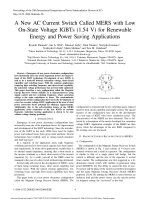
Figure 6 DC link Voltage
Diagram 6 shows the dc link voltage when the load changes and distortion in the output voltage
occurs. The dc link voltage increases to reduce the output voltage distortion. The oscillations in the
dc link voltage are due to the filter effect in the DC link reference estimation given by equation (8).
However; the oscillation portion is relatively small compared to the dc voltage portion, so that it
does not affect the output voltage.
References
[1] Takao Kawabata, Takeshi Miyashita and Yushin Yamamoto, "Digital Control of three-Phase
Inverter with LC Filter", IEEE Transactions on Power Electronics, Vol. 6, No. 1, January 1991, pp.
62-72.
[2] Takao Kawabata, Takeshi Miyashita and Yushin Yamamoto, "Dead Beat Control of three-
Phase PWM Inverter", IEEE Transactions on Power Electronics, Vol. 5, No. 1, January 1990, pp.
21-28.
[3] Osman Kükrer, "Deadbeat Control of a Three-Phase Inverter with an Output LC Filter", IEEE
Transactions on Power Electronics, Vol. 11, No. 1, January 1996, pp. 16-23.
[4] Chihchiang Hua and Richard G. Hoft, "Hight Performance Deadbeat Controlled PWM
Inverter using a Current Source Compensator for nonlinear loads", IEEE/PESC 23rd Anual, Toledo,
Spain 1992, pp. 443-450.
[5] Tomoki Yokoyama and Atsuo Kawamura, "Disturbance Observer Based Fully Digital
Controlled PWM Inverter for CVCF Operation", IEEE Transactions on Power Electronics, Vol. 9,
No. 5, September 1994, pp. 473-480.
[6] Atsuo Kawamura and Tomoki Yokoyama, "Comparison of Five Control Methods for Digitally
Feedback Controlled PWM Inverters", EPE Firenze 1991, Vol. 2, pp. 35-40.
[7] Youichi Ito and Shoichi Kawauchi, "Microprocessor-Based Robust Digital Control for UPS
with Three -Phase PWM Inverter", IEEE Transactions on Power Electronics, Vol. 10, No. 2, March
1995, pp. 196-204.
[8] Atsuo Kawamura, Toshimasa Haneyoshi and Richard G. Hoft, "Deadbeat Controlled PWM
Inverter with Parameter Estimation Using Only Voltage Sensor", IEEE Transactions on Power
Electronics, Vol. 3, No. 2, April 1988, pp. 118-125.
[9] P. R. K. Chetty "Current Injected Equivalent Circuit Approach to Modeling and Analysis of
Current Programmed Switching DC-DC Converters (Discontinuous Inductor Conduction Mode)",
IEEE Transactions on Industrial Applications, Vol. IA-18, No. 3, May/June 1982, pp. 295-299.
[10] Francisco Guinjoan, Javier Calvente, Alberto Poveda and Luis Martinez, "Large-Signal
Modeling and Simulation of Switching DC-DC Converter", IEEE Transactions on Power
Electronics, Vol. 12, No. 3, May 1997, pp. 485-494.
[11] F. Al-Hosini, ABB Corporate Research, Sweden, "An Aproximate Dead-Beat Control
stratigy for the disign of functions regulators in DC/DC Converters", EPE Trondheim 1997, Vol. 3,
pp. 155-160.