Tài liệu Home Automation Using the PIC16F877A doc
Bạn đang xem bản rút gọn của tài liệu. Xem và tải ngay bản đầy đủ của tài liệu tại đây (566 KB, 26 trang )
2002 Microchip Technology Inc. DS00236A-page 1
AN236
INTRODUCTION
X-10 is a communication protocol designed for sending
signals over 120 VAC wiring. X-10 uses 120 kHz bursts
timed with the power line zero-crossings to represent
digital information. Plug-in modules available from var-
ious vendors enable users to create home automation
systems by using the AC wiring already installed within
a home. Readers who would like an overview of the
X-10 signal format may refer to Appendix A.
PICmicro
®
microcontrollers can easily be used in
conjunction with X-10 technology to create home
automation applications. The specific PICmicro
microcontroller (MCU) used should be selected based
on RAM, ROM, operating frequency, peripheral, and
cost requirements of the particular application. The
PIC16F877A was selected for this application because
of its versatility as a general purpose microcontroller,
its FLASH program memory (for ease of development),
data EEPROM, and ample I/O.
This application note discusses the implementation of
X-10 on a PICmicro MCU to create a home controller
that can both send and receive X-10 signals. The
reader may implement the home controller as is, or
adapt the circuits and firmware to other applications. A
library of X-10 functions is provided to facilitate devel-
opment of other X-10 applications using PICmicro
MCUs (see Appendix E).
Operating instructions for the home controller are
included in Appendix B.
HARDWARE OVERVIEW
The home controller application described in this appli-
cation note allows the user to program on and off times
for up to sixteen devices, using a 2 x 16 liquid crystal
display and five push buttons. A built-in light sensor can
be used to turn on lights at dusk, and turn them off at
dawn.
The home controller is designed to facilitate experi-
mentation with home automation using the
PIC16F877A. In addition to the PIC16F877A, the board
will accept any other PICmicro MCU that shares the
same pinout, such as the PIC18F452. Therefore,
experimenters may expand on the application using the
higher performance of the PIC18 family of parts without
changing the hardware.
With care, engineers and home control enthusiasts can
experiment with home automation using the
MPLAB
®
ICD and MPLAB
®
ICD 2 development tools
or in-circuit emulator. However, proper circuit isolation
precautions must be taken to avoid damage to your
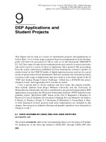
computer or development tools. See Figure 1 and the
warning note!
FIGURE 1: TEST SETUP WHEN USING DEVELOPMENT TOOLS
Author: Jon Burroughs
Microchip Technology Inc.
WARNING: VSS or ground on the application circuit is
tied to neutral of the 120 VAC. To safely connect your
development tools or computer to the home control-
ler, you must power it through an isolation transformer
and leave wall ground (the green wire in most cases)
disconnected. Any test instruments (such as an oscil-
loscope) that you hook up to the application circuit,
should be powered through the isolation transformer
as well, with wall ground disconnected. In addition,
the entire circuit should be enclosed within a suitable
case to prevent unintentional contact with the mains
voltage!
Isolation
Transformer
X-10
Lamp
Module
X-10
Board
Oscillo-
scope
X-10
Lamp
Module
X-10 modules and
any test
instruments should
be plugged into
the isolation
transformer.
To maintain
isolation, leave
ground
disconnected.
Computer,
development tools,
and the isolation
transformer should
be plugged into
the wall outlet.
X-10
®
Home Automation Using the PIC16F877A
AN236
DS00236A-page 2 2002 Microchip Technology Inc.
HARDWARE DESCRIPTION
An overview of the home controller application
hardware is shown in Figure 2.
The hardware functionality of X-10 circuitry can be
divided into four functional blocks:
• Zero-crossing detector
• 120 kHz carrier detector
• 120 kHz signal generator
• Transformerless power supply
There are several application functions that are not
directly associated with the X-10 interface. User
interface functions are accomplished with an LCD
display and five push buttons. A real-time clock is
created using Timer1 and an external 32 kHz oscillator.
User modified control data, such as unit on and off
times, are stored in the PICmicro MCU’s built-in
EEPROM. A light sensor and load switch are also used
in this application.
FIGURE 2: APPLICATION BLOCK DIAGRAM
APPLICATION SPECIFIC FUNCTIONS
USER INTERFACE
X-10 FUNCTIONS
Zero-crossing Detector
120 kHz Carrier Generator
LCD Key Switches
Real-time Clock Control Data
Storage
TRANSFORMERLESS POWER
SUPPLY
Light
Sensor
Load
Switch
120 kHz Carrier Detector
2002 Microchip Technology Inc. DS00236A-page 3
AN236
A summary of resource use can be seen in Table 1.
Details of the functional sections are discussed below.
Zero-Crossing Detector
In X-10, information is timed with the zero-crossings of
the AC power. A zero-crossing detector is easily cre-
ated by using the external interrupt on the RB0 pin and
just one external component, a resistor, to limit the
current into the PICmicro MCU (see Figure 3).
In the United States, Vrms = 117 VAC, and the peak
line voltage is 165V. If we select a resistor of 5 MΩ,
Ipeak = 165V/5 MΩ =33µA, which is well within the
current capacity of a PICmicro MCU I/O pin.
Input protection diodes (designed into the PICmicro
MCU I/O pins) clamp any voltage higher than V
DD or
lower than V
SS. Therefore, when the AC voltage is in
the negative half of its cycle, the RB0 pin will be
clamped to V
SS - 0.6V. This will be interpreted as a
logic zero. When the AC voltage rises above the input
threshold, the logical value will become a ‘1’.
In this application, RB0 is configured for external inter-
rupts, and the input buffer is a Schmitt trigger. This
makes the input threshold 0.8 V
DD = 4V on a rising
edge and 0.2 V
DD = 1V on a falling edge.
Upon each interrupt, the Interrupt Edge Select bit within
the OPTION_REG register is toggled, so that an inter-
rupt occurs on every zero-crossing. Using the following
equation, it is possible to calculate when the pin state
will change relative to the zero-crossing:
V = Vpk*sin(2*π*f*t), where Vpk = 165V and f = 60 Hz
On a rising edge, RB0 will go high about 64 µs after the
zero-crossing, and on a falling edge, it will go low about
16 µs before the zero-crossing.
More information on interfacing PICmicro MCUs to AC
power lines can be found in the application note
AN521, “Interfacing to AC Power Lines”, which is
available for download from the Microchip web site.
FIGURE 3: ZERO-CROSSING DETECTOR
TABLE 1: SUMMARY OF MICROCONTROLLER RESOURCE USE
Resource Function Description
External interrupt on RB0 Zero-crossing Detect Generates one interrupt every zero-crossing.
CCP1/Timer2 in PWM
mode
120 kHz Modulation TRISC is used to enable/disable 120 kHz output.
Main oscillator is 7.680 MHz.
Timer2 interrupt through
postscaler
Triac Dimmer Timing Generates dimmer timing increments for controlling
Triac.
Timer1 interrupt Real-time Clock Used as time keeping clock and key scan clock.
One interrupt/25 ms, 40 interrupts/1 sec.
Timer0 interrupt 120 kHz Envelope Timing Times duration of 1 ms bursts and onset of second
and third phase bursts.
ADC Light Sensor Used to detect dawn and dusk.
PORTB<1:5> Key Press Inputs Five push buttons are used for menu navigation.
PORTB<6:7> Reserved for ICD Isolation precautions required. See warning note!
PORTD<0:7> LCD Data pins 8 data lines for LCD.
PORTE<0:2> LCD Control pins 3 control lines for LCD.
DATA EEPROM Non-volatile Control Data Storage Stores on and off times and other user
programmable information.
120 VAC
R = 5 M
Ω
RB0/INT
PIC16F87XA
AN236
DS00236A-page 4 2002 Microchip Technology Inc.
120 kHz Carrier Detector
To receive X-10 signals, it is necessary to detect the
presence of the 120 kHz signal on the AC power line.
This is accomplished with a decoupling capacitor, a
high-pass filter, a tuned amplifier, and an envelope
detector. The components of the carrier detector are
illustrated in Figure 4.
Because the impedance of a capacitor is:
Zc = 1/(2*π*f*C), a 0.1 µF capacitor presents a low
impedance (13Ω) to the 120 kHz carrier frequency, but
a high impedance (26.5 kΩ) to the 60 Hz power line fre-
quency. This high-pass filter allows the 120 kHz signal
to be safely coupled to the 60 Hz power line, and it dou-
bles as the coupling stage of the 120 kHz carrier
generator described in the next section.
Since the 120 kHz carrier frequency is much higher
than the 60 Hz power line frequency, it is
straightforward to design an RC filter that will pass the
120 kHz signal and completely attenuate the 60 Hz. A
high-pass filter forms the first stage of the High-Pass
Filter and Tuned Amplifier Block, shown on sheet 5 of
the schematics in Appendix C.
For a simple high-pass filter, the -3 db breakpoint is:
ƒ3 db = 1/(2*π*R*C). For C = 150 pF and R = 33 kΩ,
ƒ3 db = 1/(2*π*150 pF *33 kΩ)=32kHz.
This ƒ3 db point assures that the 60 Hz signal is com-
pletely attenuated, while the 120 kHz signal is passed
through to the amplifier stages. Next, the 120 kHz sig-
nal is amplified using a series of inverters configured as
high gain amplifiers. The first two stages are tuned
amplifiers with peak response at 120 kHz. The next two
stages provide additional amplification. The amplified
120 kHz signal is passed through an envelope detec-
tor, formed with a diode, capacitor, and resistor. The
envelope detector output is buffered through an
inverter and presented to an input pin (RC3) of the
PIC16F877A.
Upon each zero-crossing interrupt, RC3 is simply
checked within the 1 ms transmission envelope to see
whether or not the carrier is present. The presence or
absence of the carrier represents the stream of ‘1’s and
‘0’s that form the X-10 messages described in
Appendix A.
FIGURE 4: 120 kHz CARRIER DETECTOR
PIC16F87XA
RC3
High-Pass
Filter & Tuned
Amplifier
(1)
Decoupling
Capacitor
+5 VDC
Envelope Detector
10K
10 nF
0.1
µF
X2 Rated
1 M
Ω
Note 1: See schematic in Appendix C.
2002 Microchip Technology Inc. DS00236A-page 5
AN236
120 kHz Carrier Generator
X-10 uses 120 kHz modulation to transmit information
over 60 Hz power lines. It is possible to generate the
120 kHz carrier with an external oscillator circuit. A sin-
gle I/O pin would be used to enable or disable the oscil-
lator circuit output. However, an external oscillator
circuit can be avoided by using one of the PICmicro
MCU’s CCP modules.
The CCP1 module is used in PWM mode to produce a
120 kHz square-wave with a duty cycle of 50%.
Because X-10 specifies the carrier frequency at
120 kHz (+/- 2 kHz), the system oscillator is chosen to
be 7.680 MHz, in order for the CCP to generate pre-
cisely 120 kHz. Calculations for setting the PWM
period and duty cycle are shown in the code listing
comments for the function InitPWM.
After initialization, CCP1 is continuously enabled, and
the TRISC bit for the pin is used to gate the PWM out-
put. When the TRISC bit is set, the pin is an input and
the 120 kHz signal is not presented to the pin. When
the TRISC bit is clear, the pin becomes an output and
the 120 kHz signal is coupled to the AC power line
through a transistor amplifier and capacitor, as
depicted in Figure 5.
Since the impedance of a capacitor is Zc = 1/(2*π*f*C),
a 0.1 µF capacitor presents a low impedance to the
120 kHz carrier frequency, but a high impedance to the
60 Hz power line frequency. This high-pass filter allows
the 120 kHz signal to be safely coupled to the 60 Hz
power line, and it doubles as the first stage of the
120 kHz carrier detector, described in the previous
section.
To be compatible with other X-10 receivers, the maxi-
mum delay from the zero-crossing to the beginning of
the X-10 envelope should be about 300 µs. Since the
zero-crossing detector has a maximum delay of
approximately 64 µs, the firmware must take less than
236 µs after detection of the zero-crossing to begin
transmission of the 120 kHz envelope.
Transformerless Power Supply
The PIC16F877A and other board circuits require a 5V
supply. In this application, the X-10 controller must also
transmit and receive its data over the AC line. Since
X-10 components are intended to be plugged into a
wall outlet and have a small form factor, a transformer-
less power supply is used. Two characteristics of trans-
formerless supplies that should be kept in mind are
limited current capacity, and lack of isolation from the
AC mains (see the warning note)!
Figure 6 illustrates the transformerless power supply
used in this application. To protect the circuit from
spikes on the AC power line, a 130V VDR (voltage
dependent resistor) is connected between Line and
Neutral. A Positive Temperature Coefficient (PTC)
device acts as a resettable fuse, which limits current
between Ground and Neutral. The 47Ω resistor limits
current into the circuit, and the 1 MΩ resistor provides
a discharge path for the voltage left on the capacitor
when the circuit is unplugged from the wall. Two diodes
rectify the voltage across the 1000 µF capacitor and
5.1V Zener diode to produce a 5V supply.
The reader may wish to refer to the technical brief
TB008, “Transformerless Power Supply”, available for
download from the Microchip web site, for additional
information on transformerless power supply design.
FIGURE 5: 120 kHz CARRIER GENERATOR
WARNING: This circuit is not isolated from 120 VAC.
Act with caution when constructing or using such a
circuit, and ensure that it is contained within a suitable
insulated enclosure. Follow isolation precautions to
avoid personal injury or damage to test equipment
and development tools.
0.1 µF
X2 Rated
High-Pass Filter
1 M
Ω
7.680 MHz
PIC16F87XA
RC3/CCP
+5 VDC
120 VAC
50Ω
200Ω
OSC1
OSC2
AN236
DS00236A-page 6 2002 Microchip Technology Inc.
FIGURE 6: TRANSFORMERLESS POWER SUPPLY
Load Switch
A load switch is included on the home controller so that
it may act as a lamp module, with its own house and
unit address. A Triac was selected as the load switch,
because its medium power switching capacity and
rapid switching capability make it well-suited for lamp
control and dimming.
A Triac is an inexpensive, three-terminal device that
basically acts as a high speed, bi-directional AC switch.
Two terminals, MT1 and MT2, are wired in series with
the load. A small trigger current between the gate and
MT1 allow conduction to occur between MT1 and MT2.
Current continues to flow after the gate current is
removed, as long as the load current exceeds the latch-
ing value. Because of this, the Triac will automatically
switch off near each zero-crossing as the AC voltage
falls below the latching voltage.
A Teccor
®
L4008L6 Triac was selected because it has
a sensitive gate that can be directly controlled from the
logic level output of the PICmicro MCU I/O pin. The
sensitive gate Triac can control AC current in both
directions through the device, even though the
PICmicro MCU can provide only positive voltages to
the gate.
A variable dimmer is created by including a delay
between the time of each zero-crossing and the time
that the trigger current is provided to the Triac from the
PICmicro MCU.
The design and control of a lamp dimmer using a
PICmicro MCU is discussed in detail in PICREF-4
Reference Design, “PICDIM Lamp Dimmer for the
PIC12C508”.
FIGURE 7: LOAD SWITCH/DIMMER (TRIAC)
2.25 µF
2.25 µF
5.1V Zener
1000 µF
1.1M
LN
G
+5 VDC
PTC
1N4005
1N4005
VDR
PIC16F87XA
RA5
120 VAC Out
120 VAC In
L4008L6
VSS
Return Hot
Gate
MT1
MT2
1N4148470Ω
2002 Microchip Technology Inc. DS00236A-page 7
AN236
LCD Module
The 2-line x 16-character display uses the HD44780U
Display Controller. Eight data lines and three control
lines are used to interface to the PICmicro MCU. If
fewer I/O pins are available, the LCD can be operated
in Nibble mode using only four data lines, with some
additional software overhead. A basic LCD library is
included in this application, which provides the
necessary functions for controlling this type of LCD.
Real-Time Clock
A real-time clock is implemented using Timer1. The
real-time clock keeps track of the present time using a
routine called UpdateClock. It also determines the
rate that the buttons are read by a routine called
ScanKeys.
Timer1 is set to cause an interrupt each time it
overflows. By adding a specific offset to Timer1 each
time it overflows, the time before the next overflow can
be precisely controlled. The button reading routine,
ScanKeys, is called each time a Timer1 interrupt
occurs. Since ScanKeys performs debouncing of the
button presses, a suitable rate to check the buttons is
once every 25 ms.
With a 32 kHz crystal, the counter increments once
every 31.25 µs when the prescaler is set to 1:1. In order
for Timer1 to generate an interrupt once every 25 ms,
TMR1H:TMR1L are pre-loaded with 0xFCE0h.
The Timer1 interrupt interval, or tick, can be seen in the
following equation:
(FFFFh – FCE0h)*1/32 kHz = .025 s = 1 tick
Each time ScanKeys is called (every 25 ms), it calls
UpdateClock. UpdateClock keeps track of the time
unit variables: ticks, seconds, minutes, and hours.
Since every 25 ms equals one tick, seconds are incre-
mented every 40 ticks. Minutes and hours are
incremented in a similar fashion.
Push Buttons
Five push buttons, connected to RB1-RB5, are used for
user interaction with the application. Each normally open
push button will pull a port pin low when it is pressed.
Light Sensor
To detect the ambient light level, a CdS photoresistor is
used in conjunction with an 820Ω resistor to create a
voltage divider. The voltage on the divider varies with
the intensity of ambient light and is connected to an
analog channel (AN0) of the microcontroller.
In-Circuit Debugger
RB6 and RB7 have been reserved for In-Circuit Serial
Programming
TM
(ICSP
TM
) and the in-circuit debugger
(ICD). However, do not connect the ICD or any other
development tool, without taking first isolating the
entire application from wall power (see the previous
warning notes)!
Control Data Storage
Certain control data that is programmable by the user
must be stored in non-volatile memory. The PICmicro
MCU’s built-in EEPROM is well-suited to this task.
To use EEPROM memory space most efficiently (by
avoiding wasted bits), on/off times and light sensor
control flags are stored using the format shown in
Figure 8. Figure 9 shows the location of on/off times
and other information within the data EEPROM. Using
this data organization, only 48 bytes of EEPROM are
required to store the on/off times and light sensor
control flags for 16 units.
FIGURE 8: ON/OFF TIME STORAGE
FIGURE 9: EEPROM DATA
Each time that minutes are incremented within the
UpdateClock routine, a flag is set that enables a rou-
tine called CheckOnOffTimes to be called from the
main loop. CheckOnOffTimes compares the present
time with the unit on and off times stored in EEPROM
memory. If there is a match, then a flag is set to either
turn the unit on or off, by sending it the appropriate X-10
command when the routine ControlX10Units is
called.
A = AM/PM bit for On Hour
C = AM/PM bit for Off Hour
B = Control bit for On at Dusk
D = Control bit for Off at Dawn
On Hour Off Hour
EEHours
BOnMin
EEOnMinutes
A
C D
Off Min
EEOffMinutes
4 bits 4 bits
6 bits
6 bits
11
11
OnHour OffHour
Unit 1
OnHour OffHour
OnHour OffHour
Unit 2
Unit 3
0x010
0x011
0x012
0x001
0x002
House Address
Unit Address
System
System
B OnMinA
B OnMinA
B OnMinA
Unit 1
Unit 2
Unit 3
0x020
0x021
0x022
B OffMinA
B OffMinA
B OffMinA
Unit 1
Unit 2
Unit 3
0x030
0x031
0x032
Address Unit
Data
AN236
DS00236A-page 8 2002 Microchip Technology Inc.
APPLICATION FIRMWARE
OVERVIEW
The firmware is divided into several different files to
facilitate adaptation of the code to other applications.
Following is a summary of the files associated with this
application note:
• x10lib.asm Defines X-10 functions.
• x10lib.inc Defines X-10 constants and
macros.
• x10hc.asm Main application code for the
home controller.
• x10demo.asm Example code that shows how
to use the X-10 library macros.
• lcd.asm Defines the routines necessary
for driving the LCD.
• p16f877A.lkr Standard linker file for
PIC16F877A parts.
• p16f877A.inc Standard include file for
PIC16F877A parts.
Detailed descriptions of operation can be found in the
comments within the code listing. The X-10 library
functions and macros are described in the next section.
X-10 LIBRARY
A simple library of commands was developed and used
for the home controller. It can be used with little or no
modification in a user’s application. The library consists
of two files: x10lib.asm and x10lib.inc.
To use the library, a user need only understand the
function of the macros defined in x10lib.inc. The
macros greatly simplify the use of the library by elimi-
nating the need for the user to understand every X-10
function in x10lib.asm. Examples of how the macros
are used are included in the file x10demo.asm.
The macros are explained below:
InitX10
This macro is used to initialize the peripherals that pro-
vide X-10 functionality. It must be called in the applica-
tion program before any of the below macros will work.
It is used as follows:
InitX10
SkipIfTxReady
Before sending an X-10 message, it is necessary to
make sure that another message is not already being
sent, which is signified by the X10TxFlag being set.
This macro simply checks that flag and skips the next
instruction if it is okay to begin a new transmission.
Otherwise, there is a chance that a new transmission
will interrupt an ongoing transmission.
It is used as follows:
SkipIfTxDone
GOTO $-1 ;loop until ready to
;transmit next message
SendX10Address (House, Unit)
This macro is used to send an X-10 address for a par-
ticular unit. It requires two arguments, a house address
and unit address. The definitions for all house and unit
addresses are defined in x10lib.inc. To use this
macro to send the address for unit 16 at house P, one
simply types:
SendX10Address HouseP, Unit16
SendX10AddressVar
This macro is used to send an X-10 address, defined
by variables rather than constants. To send an address
contained in the user variables MyHouse and MyUnit,
the following sequence would be applied:
MOVF MyHouse, W ;contains a value
;from 0-16
MOVWF TxHouse
MOVF MyUnit, W ;contains a value
;from 0-16
MOVWF TxUnit
SendX10AddressVar
2002 Microchip Technology Inc. DS00236A-page 9
AN236
SendX10Command (House, Function)
This macro is used to send an X-10 command. It
requires two arguments, the house address and func-
tion code. The definitions for all house addresses and
function codes are defined in x10lib.inc. To use this
macro to send the command ‘All Lights On’ to all units
at house A, one types:
SendX10Command HouseA, AllLightsOn
SendX10CommandVar
This macro is used to send an X-10 command, defined
by a variable rather than a constant. To use this macro
to send the command stored in the user variable
MyCommand to all units at MyHouse, one types:
MOVF MyHouse, W ;contains a value
;from 0-16
MOVWF TxHouse
MOVF MyCommand, W ;any X-10
;function
;defined in
;x10lib.inc
MOVWF TxFunction
SendX10CommandVar
SkipIfRxDone
Before reading an X-10 message, it is necessary to
make sure that a complete message has been
received. This is signified by the X10RxFlag being set.
This macro simply checks that flag and skips the next
instruction if a new X-10 message has been received.
It is used as follows:
SkipIfRxDone
GOTO $-1 ;loop until message
;received
SkipIfAddressRcvd
It may be necessary to make sure that an address was
received by using this macro, which checks to see if the
RxCommandFlag is clear.
It is used as follows:
SkipIfAddressRcvd
GOTO $-1 ;loop until address
;received
SkipIfCommandRcvd
Or, it may be necessary to make sure that a command
was received by using this macro, which checks to see
if the RxCommandFlag is set.
It is used as follows:
SkipIfCommandRcvd
GOTO $-1 ;loop until command
;received
ReadX10Message
This macro is called to read a received X-10 message,
which may be either an address or a command. If the
message was an address, then the received house and
unit codes will be stored in the variables RxHouse and
RxUnit, respectively. If the message was a command,
then the received house address and function code will
be stored in the variables RxHouse and RxFunction.
It is simply called as follows:
ReadX10Message
Please refer to the example code in x10demo.asm to
see how each of these macros is used in a simple
application.
AN236
DS00236A-page 10 2002 Microchip Technology Inc.
Memory Usage
Memory usage for the X-10 portion of the application is
summarized in Table 2.
TABLE 2: SUMMARY OF MEMORY USAGE FOR X-10 FUNCTIONALITY
Memory usage for the entire home controller
application is summarized in Table 3.
TABLE 3: SUMMARY OF MEMORY USAGE FOR THE HOME CONTROLLER
Memory Type Used Available on PIC16F877A Percent Used
FLASH Program Memory 437 words 8453 words 5%
Data Memory (RAM) 62 bytes 368 bytes 17%
EEPROM Data Memory 0 bytes 256 bytes 0%
Memory Type Used Available on PIC16F877A Percent Used
FLASH Program Memory 3762 words 8453 words 44.5%
Data Memory (RAM) 168 bytes 368 bytes 45.6%
EEPROM Data Memory 51 bytes 256 bytes 20%
2002 Microchip Technology Inc. DS00236A-page 11
AN236
CONCLUSION
The PICmicro MCU is well-suited to X-10 applications.
With its plethora of on-chip peripherals and a few exter-
nal components, a PICmicro MCU can be used to
implement an X-10 system that can transmit and
receive messages over the AC power line wiring. The
small code size of the X-10 library leaves ample space
for the user to create application specific code.
PICmicro MCUs, such as the PIC16F877A, have plenty
of additional resources for creating more complex X-10
applications, while smaller PICmicro MCUs can be
selected for economical use in simpler X-10
applications.
USEFUL WEB REFERENCES
• />This web site describes how to build an appliance
module that utilizes the PIC16C52 or PIC16F84.
Parts of this project’s receiver circuit, designed by
Phil Plunkett, were adapted to the home controller
application.
•
The Microchip web site features data sheets, product
information, and more. Helpful technical
documentation available here include:
AN521 “Interfacing to AC Power Lines”
TB008 “Transformerless Power Supply”
PICREF-4 “PICDIM Lamp Dimmer for the
PIC12C508”
•
The X10 Wireless Technology, Inc.
TM
web site fea-
tures technical information and FAQs pertaining to
the X-10 communication protocol.
AN236
DS00236A-page 12 2002 Microchip Technology Inc.
APPENDIX A: HOW DOES THE X-10
PROTOCOL WORK?
X-10 transmissions are synchronized with the
zero-crossings on the AC power line. By monitoring for
the zero-crossings, X-10 devices know when to trans-
mit or receive X-10 information. A binary ‘1’ is repre-
sented by a 1 ms long burst of 120 kHz, near the
zero-crossing point of the AC. A binary zero is
represented by the lack of the 120 kHz burst.
FIGURE A-1: X-10 TRANSMISSION TIMING
A complete X-10 message is composed of a start code
(1110), followed by a house code, followed by a key
code. The key code may be either a unit address or a
function code, depending on whether the message is
an address or a command. Table A-1 and Table A-2
show the possible values of the house and key codes.
60 Hz
120 kHz
1 ms
2.778 ms
5.556 ms
8.333 ms
Note 1: These 120 kHz carrier bursts are timed to coincide with the zero-crossing of the other phases,
when implemented.
(1)
(1)
(1)
(1)
2002 Microchip Technology Inc. DS00236A-page 13
AN236
TABLE A-1: HOUSE CODES
TABLE A-2: KEY CODES
When transmitting the codes in Table A-1 and
Table A-2, two zero-crossings are used to transmit
each bit as complementary bit pairs (i.e., a zero is rep-
resented by 0-1, and a one is represented by 1-0). For
example, in order to send the house code A, the four-bit
code in Table A-1 is 0110, and the code transmitted as
complimentary bit pairs is 01101001. Since house and
key codes are sent using the complimentary format, the
start code is the only place where the pattern 1110 will
appear in an X-10 data stream.
The key code, which is 5-bits long in Table A-2, takes
10 bits to represent in the complimentary format.
Because the last bit of the key code is always zero for
a unit address and one for a function code, the last bit
of the key code can be treated as a suffix that denotes
whether the key code is a unit address or function
code.
A complete block of data consists of the start code,
house code, key code and suffix. Each data block is
sent twice, with 3 power line cycles, or six
zero-crossings, between each pair of data blocks.
For example, to turn on an X-10 module assigned to
house code A, unit 2, the following data stream would
be sent on the power line, one bit per zero-crossing.
First, send the address twice:
Next, wait for three cycles (six zero-crossings):
Then, send the command twice:
Lastly, wait for three cycles (six zero-crossings) before
sending the next block:
There are exceptions to this format. For example, the
bright and dim codes do not require the 3-cycle wait
between consecutive dim commands or consecutive
bright commands. For a complete discussion of all
X-10 messages, please refer to the X10 Wireless
Technology, Inc. web site (see the "USEFUL WEB
REFERENCES" section).
House
Addresses
House Codes
H1 H2 H4 H8
A 0110
B 1110
C 0010
D 1010
E 0001
F 1001
G 0101
H 1101
I 0111
J 1111
K 0011
L 1011
M 0000
N 1000
O 0100
P 1100
Unit Addresses
Key Codes
D1 D2 D4 D8 D16
1 01100
2 11100
3 00100
4 10100
5 00010
6 10010
7 01010
8 11010
9 01110
10 11110
11 00110
12 10110
13 00000
14 10000
15 01000
16 11000
Function Codes
All Units Off 00001
All Units On 00011
On 00101
Off 00111
Dim 01001
Bright 01011
All Lights Off 01101
Extended Code 01111
Hail Request 10001
Hail Acknowledge 10011
Pre-set Dim 101X1
Extended Code
(Analog)
11001
Status = On 11011
Status = Off 11101
Status Request 11111
1110 01101001 10101001 01
START HOUSE A UNIT 2 Suffix
1110 01101001 10101001 01
START HOUSE A UNIT 2 Suffix
000000
1110 01101001 01011001 10
START HOUSE A ON Suffix
1110 01101001 01011001 10
START HOUSE A ON Suffix
000000
AN236
DS00236A-page 14 2002 Microchip Technology Inc.
APPENDIX B: HOME CONTROLLER
OPERATING
INSTRUCTIONS
Welcome Screen
The home controller user interface consists of five but-
tons and a 2 x 16 LCD. Upon power-up, the Welcome
screen is displayed. This screen displays a welcome
message and the time. Immediately, the seconds begin
incrementing and the PICmicro MCU begins keeping
track of the time.
Figure B-1 shows the Welcome screen and the location
and functionality of each button. Depending on the
screen viewed, each of the five buttons performs a
different function.
When the Welcome screen is displayed, the buttons
enable access to the following functions:
•Press menu to enter the Select Function screen.
•Press up to brighten the lamp that is plugged into
the home controller.
•Press down to dim the lamp.
•Press enter to turn the lamp on.
•Press exit to turn the lamp off.
FIGURE B-1: WELCOME SCREEN
Select Function Screen
When viewing the Welcome screen, the menu button
enables access to the Select Function screen. Each
successive press of the menu button cycles through
the four main functions of the user interface: setting the
system time, setting the system address, setting the
light sensor, or programming the unit on and off times,
as illustrated in Figure B-2.
FIGURE B-2: SELECT FUNCTION
SCREENS
Set System Time Screen
Use the Set System Time screen to set the time.
SETTING SYSTEM TIME
1. Starting from the Welcome screen, press menu
until the Set System Time screen is displayed
and press enter.
2. Press up/down to set the hours.
3. Press enter when the correct hour, including AM
or PM, has been selected.
4. Repeat this process to set the minutes.
5. If the time is correct, select Y (the default) using
the up/down buttons and press enter. This
returns to the Welcome screen with the new
time displayed.
6. If the time is not correct, select N and press
enter. This will return the user to step 2 so the
correct time can be entered.
7. Press exit at any time to return the user to the
Welcome screen without saving the new time.
FIGURE B-3: SET SYSTEM TIME SCREENS
Welcome Home
12:00:00 AM
menu up down
enter
exit
1
2
3
4
menu up down
enter
exit
menu up down
enter
exit
menu up down
enter
exit
menu up down
enter
exit
Select Function
Program Unit
Select Function
Set Light Sensor
Select Function
Set System Addr
Select Function
Set System Time
menu up down
enter
exit
menu up down
enter
exit
1
2
menu up down
enter
3
exit
Set System Time
12:00 AM Set hrs
Set System Time
12:00 AM Set min
Set System Time
12:00 AM Okay? Y
2002 Microchip Technology Inc. DS00236A-page 15
AN236
Select System Address Screen
Use the Set System Address screen to set the house
address and unit address of the home controller.
SETTING HOUSE/UNIT ADDRESS
1. From the Welcome screen, press menu until the
Set System Addr screen is displayed and press
enter.
2. Press up or down to set the house address (a
letter from A - P).
3. Press enter when the house address has been
selected.
4. Repeat steps 2 and 3 to set the unit address (a
number from 1 - 16).
5. If the house and unit addresses are correct,
select Y (the default) using the up/down buttons
and press enter. This returns to the Welcome
screen with the new address stored in
non-volatile memory.
6. If the address is not correct, select N and press
enter. This will return the user to step 2.
7. Press exit at any time to return the user to the
Welcome screen without saving the new
address.
FIGURE B-4: SET SYSTEM ADDRESS
SCREENS
Set Light Sensor Screen
Use the Set Light Sensor screen to select whether
units turn on at dusk, or off at dawn.
SETTING THE LIGHT SENSOR
1. From the Welcome screen, press menu until the
Set Light Sensor screen is displayed and press
enter.
2. Press up or down to select the desired unit. The
house address will already be set to the system
house address.
3. Press enter when the desired unit address has
been selected.
4. Press up or down to select whether or not the
unit should turn on at dusk, and press enter.
5. Repeat this process to set other units as
desired.
6. Press exit to return to the Welcome screen.
Pressing exit while the “On at Dusk” or “Off at
Dawn” prompt is displayed will return the user to
the Welcome screen without modifying that
parameter.
FIGURE B-5: SET LIGHT SENSOR
SCREENS
menu up down
enter
exit
menu up down
enter
exit
1
2
menu up down enter
3
exit
Set System Addr
A-01 Set House
Set System Addr
A-01 Set Unit
Set System Addr
A-01 Okay? Y
menu up down
enter
exit
menu up down
enter
exit
1
2
menu up down enter
3
exit
Set Light Sensor
A-01 Set Unit
Set Light Sensor
On at Dusk? Y
Set Light Sensor
Off at Dawn? Y
AN236
DS00236A-page 16 2002 Microchip Technology Inc.
Program Unit Screen
Use the Program Unit screen to program on and off
times for different units.
PROGRAMMING UNIT ON AND OFF TIMES
1. From the Welcome screen, press menu repeat-
edly until the Program Unit screen is displayed
and press enter.
2. Press up or down to select the desired unit. The
house address will already be set to the system
house address.
3. Press enter when the unit address has been
selected.
4. Press up or down to set the ‘on’ time hours.
Hours set to ‘00’ means that the unit will not be
turned on at any time.
5. Press enter when the correct hour, including AM
or PM, has been selected.
6. Repeat this process to set the ‘on’ time minutes.
If the hour has been set to ‘00’, then the minutes
will be set to ‘00’ automatically.
7. If the time is correct, select Y (the default) using
the up/down buttons and press enter. The user
will be prompted to program the ‘off’ time in a
similar fashion.
8. If the time is not correct, select N and press
enter. This allows the user to re-enter the hour
and minutes by returning to step 2.
9. Repeat this process to set the ‘on’ and ‘off’ time
for other units as desired.
10. Press exit to return to the Welcome screen.
Pressing exit while the “Set Hours” or “Set Min”
prompt is displayed will return the user to the
Welcome screen without modifying any
parameters.
FIGURE B-6: PROGRAM UNIT ‘ON’ TIME
SCREENS
menu up down
enter
exit
menu up down
enter
exit
menu up down
enter
exit
menu up down
enter
exit
Program On-Time
00:00AM Set min
Program On-Time
00:00AM Okay? Y
Program On-Time
00:00AM Set hrs
Program Unit
A-01 Set Unit
Y
menu up down
enter
exit
Program Off-Time
00:00AM Set hrs
menu up down
enter
exit
Program Off-Time
00:00AM Set min
menu up down
enter
exit
Program Off-Time
00:00AM Okay? Y
N
N
Y
2002 Microchip Technology Inc. DS00236A-page 17
AN236
APPENDIX C: X-10 SCHEMATICS
FIGURE C-1: SHEET 1 OF 5
UP
XIN
RD1
RD4
RD7
RE2
XOUT
RD3
RD2
RD0
RE1
RE0
RD6
RD5
ENTER
MCLR
DOWN
MENU
EXIT
TRIAC
ZEROX
CDS
U1
AN236
DS00236A-page 18 2002 Microchip Technology Inc.
FIGURE C-2: SHEET 2 OF 5
RE0
RD6
RD3
RD0
EXIT
RE1
RE2
DOWN
RD7
RD2
RD1
RD4
ENTER
RD5
MENU
UP
CDS
LCD1
2002 Microchip Technology Inc. DS00236A-page 19
AN236
FIGURE C-3: SHEET 3 OF 5
+5V
TRIAC
XIOCIRCUITS
AN236
DS00236A-page 20 2002 Microchip Technology Inc.
FIGURE C-4: SHEET 4 OF 5
XIOCIRCUITS
XOUT
CARRIERDATA
ZEROX
2002 Microchip Technology Inc. DS00236A-page 21
AN236
FIGURE C-5: SHEET 5 OF 5
XIN
CARRIERDATA
AN236
DS00236A-page 22 2002 Microchip Technology Inc.
APPENDIX D: PARTS LIST
Count Reference Value Description
2 D7, D8 6.8V Zener Diode
2 D4, D5 1N4005 Diode
2 D3, D9 1N4148 Diode
1 D6 5.1V Zener Diode
1 Q2 2N2222 NPN Transistor
1 J2 Power In Connector
2 J1 Power Out Connector
1 U2 CD4069 HEX Inverters
8 C1, C2, C3, C8, C9, C10, C11, C12 0.1 µF Capacitor
4 C4, C5, C6, C7 15 pF Capacitor
1 C13 0.1 µF Capacitor
2 C14, C15 2.25 µF, 250V x2 Capacitor
2 C21, C22 3.3 nF Capacitor
2 C25, C26 4.7 nF Capacitor
1 C20 10 nF Capacitor
2 C23, C24 10 pF Capacitor
1 C27 100 pF Capacitor
2 C18, C19 150 pF Capacitor
1 C16 1000 µF, 25V Capacitor
1 C17 0.1 µF, 275 VAC x2 Capacitor
1 Y2 7.680 MHz Crystal
1Y1 32 kHz Crystal
2 L1, L2 220 µH Axial Lead Inductor
1 LCD1 CG161 HD44780-based 2x16 Liquid Crystal Display
2 D1, D2 LTL-94PEKTA LEDs
1 U1 PIC16F877A Microcontroller
1R6 20 kΩ Potentiometer
1PTC1 CdS Cell
1 PTC2 Resettable PTC's Resistor
1 R18 1 MΩ Resistor
1 R14 1.1 MΩ Resistor
1 R13 2 MΩ Resistor
1 R17 5 MΩ Resistor
7 R1, R4, R5, R7, R8, R9, R21 10 kΩ Resistor
1 R22 33 kΩ Resistor
1 R25 47 kΩ Resistor
1 R19 50 kΩ Resistor
1 R16 100 kΩ Resistor
2 R15, R23 100 kΩ Resistor
1 R20 200Ω Resistor
1 R24 220 kΩ Resistor
2 R2, R3 680Ω Resistor
1 R10 820Ω Resistor
1R11 470Ω Resistor
1 R12 470 kΩ Resistor
1 R26 10 MΩ Resistor
6 S1, S2, S3, S4, S5, S6 Push Button Switches
7 P1, P2, P3, P4, P5, P6, P7 Test Points
1 Q1 TIC206D Sensitive Gate Triac
1 VDR1 130V Varistor (Voltage Dependent Resistor)
2002 Microchip Technology Inc. DS00236A-page 23
AN236
APPENDIX E: SOURCE CODE
Due to size considerations, the complete source code
for this application note is not included in the text. A
complete version of the source code, with all required
support files, is available for download as a Zip archive
from the Microchip web site, at:
www.microchip.com
AN236
DS00236A-page 24 2002 Microchip Technology Inc.
NOTES:
2002 Microchip Technology Inc. DS00236A - page 25
Information contained in this publication regarding device
applications and the like is intended through suggestion only
and may be superseded by updates. It is your responsibility to
ensure that your application meets with your specifications.
No representation or warranty is given and no liability is
assumed by Microchip Technology Incorporated with respect
to the accuracy or use of such information, or infringement of
patents or other intellectual property rights arising from such
use or otherwise. Use of Microchip’s products as critical com-
ponents in life support systems is not authorized except with
express written approval by Microchip. No licenses are con-
veyed, implicitly or otherwise, under any intellectual property
rights.
Trademarks
The Microchip name and logo, the Microchip logo, K
EELOQ,
MPLAB, PIC, PICmicro, PICSTART and PRO MATE are
registered trademarks of Microchip Technology Incorporated
in the U.S.A. and other countries.
FilterLab, microID, MXDEV, MXLAB, PICMASTER, SEEVAL
and The Embedded Control Solutions Company are
registered trademarks of Microchip Technology Incorporated
in the U.S.A.
dsPIC, dsPICDEM.net, ECONOMONITOR, FanSense,
FlexROM, fuzzyLAB, In-Circuit Serial Programming, ICSP,
ICEPIC, microPort, Migratable Memory, MPASM, MPLIB,
MPLINK, MPSIM, PICC, PICDEM, PICDEM.net, rfPIC, Select
Mode and Total Endurance are trademarks of Microchip
Technology Incorporated in the U.S.A. and other countries.
Serialized Quick Turn Programming (SQTP) is a service mark
of Microchip Technology Incorporated in the U.S.A.
All other trademarks mentioned herein are property of their
respective companies.
© 2002, Microchip Technology Incorporated, Printed in the
U.S.A., All Rights Reserved.
Printed on recycled paper.
Microchip received QS-9000 quality system
certification for its worldwide headquarters,
design and wafer fabrication facilities in
Chandler and Tempe, Arizona in July 1999
and Mountain View, California in March 2002.
The Company’s quality system processes and
procedures are QS-9000 compliant for its
PICmicro
®
8-bit MCUs, KEELOQ
®
code hopping
devices, Serial EEPROMs, microperipherals,
non-volatile memory and analog products. In
addition, Microchip’s quality system for the
design and manufacture of development
systems is ISO 9001 certified.
Note the following details of the code protection feature on PICmicro
®
MCUs.
• The PICmicro family meets the specifications contained in the Microchip Data Sheet.
• Microchip believes that its family of PICmicro microcontrollers is one of the most secure products of its kind on the market today,
when used in the intended manner and under normal conditions.
• There are dishonest and possibly illegal methods used to breach the code protection feature. All of these methods, to our knowl-
edge, require using the PICmicro microcontroller in a manner outside the operating specifications contained in the data sheet.
The person doing so may be engaged in theft of intellectual property.
• Microchip is willing to work with the customer who is concerned about the integrity of their code.
• Neither Microchip nor any other semiconductor manufacturer can guarantee the security of their code. Code protection does not
mean that we are guaranteeing the product as “unbreakable”.
• Code protection is constantly evolving. We at Microchip are committed to continuously improving the code protection features of
our product.
If you have any further questions about this matter, please contact the local sales office nearest to you.