Tài liệu Bearing Design in Machinery P1 doc
Bạn đang xem bản rút gọn của tài liệu. Xem và tải ngay bản đầy đủ của tài liệu tại đây (525.87 KB, 40 trang )
ISBN: 0-8247-0703-6
This book is printed on acid-free paper.
Headquarters
Marcel Dekker, Inc.
270 Madison Avenue, New York, NY 10016
tel: 212-696-9000; fax: 212-685-4540
Eastern Hemisphere Distribution
Hutgasse 4, Postfach 812, CH-4001 Basel, Switzerland
tel: 41-61-260-6300; fax: 41-61-260-6333
World Wide Web
http:==www.dekker com
The publisher offers discounts on this book when ordered in bulk quantities. For more
information, write to Special Sales=Professional Marketing at the headquarters address
above.
Copyright # 2003 by Marcel Dekker, Inc. All Rights Reserved.
Neither this book nor any part may be reproduced or transmitted in any form or by any
means, electronic or mechanical, including photocopying, microfilming, and recording, or
by any information storage and retrieval system, without permission in writing from the
publisher.
Current printing (last digit):
10987654321
PRINTED IN THE UNITED STATES OF AMERICA
Copyright 2003 by Marcel Dekker, Inc. All Rights Reserved.
To Renana, Amir, and Alon
Copyright 2003 by Marcel Dekker, Inc. All Rights Reserved.
Preface
Most engineering schools offer senior courses in bearing design in machinery.
These courses are offered under various titles, such as Tribology, Bearings and
Bearing Lubrication, and Advanced Machine Design. This book is intended for
use as a textbook for these and similar courses for undergraduate students and for
self-study by engineers involved in design, maintenance, and development of
machinery. The text includes many examples of problems directly related to
important design cases, which are often encountered by engineers. In addition,
students will find this book useful as a reference for design projects and machine
design courses.
Engineers have already realized that there is a need for a basic course and a
textbook for undergraduate students that does not focus on only one bearing type,
such as a hydrodynamic bearing or a rolling-element bearing, but presents the big
picture—an overview of all bearing types. This course should cover the funda-
mental aspects of bearing selection, design, and tribology. Design engineers
require much more knowledge for bearing design than is usually taught in
machine design courses.
This book was developed to fill this need. The unique approach of this text
is that it is not intended only for scientists and graduate students, but it is
specifically tailored as a basic practical course for engineers. For this purpose, the
traditional complex material of bearing design was simplified and presented in a
methodical way that is easily understood, and illustrated by many examples.
Copyright 2003 by Marcel Dekker, Inc. All Rights Reserved.
However, this text also includes chapters for advanced studies, to upgrade the text
for graduate-level courses.
Engineering schools continually strive to strengthen the design component
of engineering education, in order to meet the need of the industry, and this text is
intended to satisfy this requirement. Whenever an engineer faces the task of
designing a machine, his first questions are often which bearings to select and
how to arrange them, and how to house, lubricate and seal the bearings.
Appropriate bearing design is essential for a reliable machine operation, because
bearings wear out and fail by fatigue, causing a breakdown in machine operation.
I have used the material in this book for many years to teach a tribology
course for senior undergraduate students and for an advanced course, Bearings
and Bearing Lubrication, for graduate students. The book has benefited from
the teaching experience and constructive comments of the students over the
years.
The first objective of this text is to present the high-level theory in bearing
design in a simplified form, with an emphasis on the basic physical concepts. For
example, the hydrodynamic fluid film theory is presented in basic terms, without
resorting to complex fluid dynamic derivations. The complex mathematical
integration required for solving the pressure wave in fluid-film bearings is
replaced in many cases by a simple numerical integration, which the students
and engineers may prefer to perform with the aid of a personal computer. The
complex calculations of contact stresses in rolling-element bearings are also
presented in a simplified practical form for design engineers.
The second objective is that the text be self-contained, and the explanation
of the material be based on first principles. This means that engineers of various
backgrounds can study this text without prerequisite advanced courses.
The third objective is not to dwell only on theory and calculations, but
rather to emphasize the practical aspects of bearing design, such as bearings
arrangement, high-temperature considerations, tolerances, and material selection.
In the past, engineers gained this expert knowledge only after many years of
experience. This knowledge is demonstrated in this text by a large number of
drawings of design examples and case studies from various industries. In
addition, important economical considerations are included. For bearing selection
and design, engineers must consider the initial cost of each component as well as
the long-term maintenance expenses.
The fourth objective is to encourage students to innovate design ideas and
unique solutions to bearing design problems. For this purpose, several case
studies of interesting and unique solutions are included in this text.
In the last few decades, there has been remarkable progress in machinery
and there is an ever-increasing requirement for better bearings that can operate
at higher speeds, under higher loads, and at higher temperatures. In response to
this need, a large volume of experimental and analytical research has been
Copyright 2003 by Marcel Dekker, Inc. All Rights Reserved.
conducted that is directly related to bearing design. Another purpose of this text is
to make the vast amount of accumulated knowledge readily available to
engineers.
In many cases, bearings are selected by using manufacturers’ catalogs of
rolling-element bearings. However, as is shown in this text, rolling bearings are
only one choice, and depending on the application, other bearing types can be
more suitable or more economical for a specific application. This book reviews
the merits of other bearing types to guide engineers.
Bearing design requires an interdisciplinary background. It involves calcu-
lations that are based on the principles of fluid mechanics, solid mechanics, and
material science. The examples in the book are important to show how all these
engineering principles are used in practice. In particular, the examples are
necessary for self-study by engineers, to answer the questions that remain after
reading the theoretical part of the text.
Extensive use is made of the recent development in computers and software
for solving basic bearing design problems. In the past, engineers involved in
bearing design spent a lot of time and effort on analytical derivations, particularly
on complicated mathematical integration for calculating the load capacity of
hydrodynamic bearings. Recently, all this work was made easier by computer-
aided numerical integration. The examples in this text emphasize the use of
computers for bearing design.
Chapter 1 is a survey of the various bearing types; the advantages and
limitations of each bearing type are discussed. The second chapter deals with
lubricant viscosity, its measurement, and variable viscosity as a function of
temperature and pressure. Chapter 3 deals with the characteristics of lubricants,
including mineral and synthetic oils and greases, as well as the many additives
used to enhance the desired properties.
Chapters 4–7 deal with the operation of fluid-film bearings. The hydro-
dynamic lubrication theory is presented from first principles, and examples of
calculations of the pressure wave and load capacity are included. Chapter 8 deals
with the use of charts for practical bearing design procedures, and estimation of
the operation temperature of the oil. Chapter 9 presents practical examples of
widely used hydrodynamic bearings that overcome the limitations of the common
hydrodynamic journal bearings. Chapter 10 covers the design of hydrostatic pad
bearings in which an external pump generates the pressure. The complete
hydraulic system is discussed.
Chapter 11 deals with bearing materials. The basic principles of practical
tribology (friction and wear) for various materials are introduced. Metals and
nonmetals such as plastics and ceramics as well as composite materials are
included.
Copyright 2003 by Marcel Dekker, Inc. All Rights Reserved.
Chapters 12 and 13 deal with rolling element bearings. In Chapter 12, the
calculations of the contact stresses in rolling bearings and elastohydrodynamic
lubrication are presented with practical examples. In Chapter 13, the practical
aspects of rolling bearing lubrication are presented. In addition, the selection of
rolling bearings is outlined, with examples. Most important, the design consid-
erations of bearing arrangement are discussed, and examples provided. Chapter
14 covers the subject of bearing testing under static and dynamic conditions.
Chapter 15 deals with hydrodynamic journal bearings under dynamic load.
It describes the use of computers for solving the trajectory of the journal center
under dynamic conditions. Chapters 16 and 17 deal with friction characteristics
and modeling of dynamic friction, which has found important applications in
control of machines with friction. Chapter 18 presents a unique case study of
composite bearing—hydrodynamic and rolling-element bearing in series. Chapter
19 deals with viscoelastic (non-Newtonian) lubricants, such as the VI improved
oils, and Chapter 20 describes the operation of natural human joints as well as the
challenges in the development of artificial joint implants.
I acknowledge the constructive comments of many colleagues and engi-
neers involved in bearing design, and the industrial publications and advice
provided by the members of the Society of Tribology and Lubrication Engineers.
Many graduates who had taken this course have already used the preliminary
notes for actual design and provided valuable feedback and important comments.
I am grateful to my graduate and undergraduate students, whose valuable
comments were instrumental in making the text easily understood. Many solved
problems were added because the students felt that they were necessary for
unambiguous understanding of the many details of bearing design. Also, I wish to
express my appreciation to Ted Allen and Marcel Dekker, Inc., for the great help
and support with this project.
I acknowledge all the companies that provided materials and drawings, in
particular, FAG and SKF. I am also pleased to thank the graduate students Simon
Cohn and Max Roman for conducting experiments that are included in the text,
helping with drawings, and reviewing examples, and Gaurav Dave, for help with
the artwork.
Special thanks to my son, Amir Harnoy, who followed the progress of the
writing of this text, and continually provided important suggestions. Amir is a
mechanical project engineer who tested the text in actual designs for the
aerospace industry. Last but not least, particular gratitude to my wife, Renana,
for help and encouragement during the long creation of this project.
Avraham Harnoy
Copyright 2003 by Marcel Dekker, Inc. All Rights Reserved.
Table of Contents
Preface
Symbols
Chapter 1 Classification and Selection of Bearings
1.1 Introduction
1.2 Dry and Boundary Lubrication Bearings
1.3 Hydrodynamic Bearing
1.4 Hydrostatic Bearing
1.5 Magnetic Bearing
1.6 Rolling Element Bearings
1.7 Selection Criteria
1.8 Bearings for Precision Applications
1.9 Noncontact Bearings for Precision Application
1.10 Bearing Subjected to Frequent Starts and Stops
1.11 Example Problems
Chapter 2 Lubricant Viscosity
2.1 Introduction
2.2 Simple Shear Flow
Copyright 2003 by Marcel Dekker, Inc. All Rights Reserved.
2.3 Boundary Conditions of Flow
2.4 Viscosity Units
2.5 Viscosity–Temperature Curves
2.6 Viscosity Index
2.7 Viscosity as a Function of Pressure
2.8 Viscosity as a Function of Shear Rate
2.9 Viscoelastic Lubricants
Chapter 3 Fundamental Properties of Lubricants
3.1 Introduction
3.2 Crude Oils
3.3 Base Oil Components
3.4 Synthetic Oils
3.5 Greases
3.6 Additives to Lubricants
Chapter 4 Principles of Hydrodynamic Lubrication
4.1 Introduction
4.2 Assumptions of Hydrodynamic Lubrication Theory
4.3 Hydrodynamic Long Bearing
4.4 Differential Equation of Fluid Motion
4.5 Flow in a Long Bearing
4.6 Pressure Wave
4.7 Plane-Slider Load Capacity
4.8 Viscous Friction Force in a Plane-Slider
4.9 Flow Between Two Parallel Plates
4.10 Fluid-Film Between a Cylinder and Flat Plate
4.11 Solution in Dimensionless Terms
Chapter 5 Basic Hydrodynamic Equations
5.1 Navier–Stokes Equations
5.2 Reynolds Hydrodynamic Lubrication Equation
5.3 Wide Plane-Slider
5.4 Fluid Film Between a Flat Plate and a Cylinder
5.5 Transition to Turbulence
5.6 Cylindrical Coordinates
5.7 Squeeze-Film Flow
Copyright 2003 by Marcel Dekker, Inc. All Rights Reserved.
Chapter 6 Long Hydrodynamic Journal Bearing
6.1 Introduction
6.2 Reynolds Equation for a Journal Bearing
6.3 Journal Bearing with Rotating Sleeve
6.4 Combined Rolling and Sliding
6.5 Pressure Wave in a Long Journal Bearing
6.6 Sommerfeld Solution of the Pressure Wave
6.7 Journal Bearing Load Capacity
6.8 Load Capacity Based on Sommerfeld Conditions
6.9 Friction in a Long Journal Bearing
6.10 Power Loss on Viscous Friction
6.11 Sommerfeld Number
6.12 Practical Pressure Boundary Conditions
Chapter 7 Short Journal Bearings
7.1 Introduction
7.2 Short-Bearing Analysis
7.3 Flow in the Axial Direction
7.4 Sommerfeld Number of a Short Bearing
7.5 Viscous Friction
7.6 Journal Bearing Stiffness
Chapter 8 Design Charts for Finite-Length Journal Bearings
8.1 Introduction
8.2 Design Procedure
8.3 Minimum Film Thickness
8.4 Raimondi and Boyd Charts and Tables
8.5 Fluid Film Temperature
8.6 Peak Temperature in Large, Heavily Loaded Bearings
8.7 Design Based on Experimental Curves
Chapter 9 Practical Applications of Journal Bearings
9.1 Introduction
9.2 Hydrodynamic Bearing Whirl
9.3 Elliptical Bearings
9.4 Three-Lobe Bearings
Copyright 2003 by Marcel Dekker, Inc. All Rights Reserved.
9.5 Pivoted-Pad Journal Bearing
9.6 Bearings Made of Compliant Materials
9.7 Foil Bearings
9.8 Analysis of a Foil Bearing
9.9 Foil Bearings in High-Speed Turbines
9.10 Design Example of a Compliant Bearing
Chapter 10 Hydrostatic Bearings
10.1 Introduction
10.2 Hydrostatic Circular Pads
10.3 Radial Pressure Distribution and Load Capacity
10.4 Power Losses in the Hydrostatic Pad
10.5 Optimization for Minimum Power Loss
10.6 Long Rectangular Hydrostatic Bearings
10.7 Multidirectional Hydrostatic Support
10.8 Hydrostatic Pad Stiffness for Constant Flow-Rate
10.9 Constant-Pressure-Supply Pads with Restrictors
10.10 Analysis of Stiffness for a Constant Pressure Supply
10.11 Journal Bearing Cross-Stiffness
10.12 Applications
10.13 Hydraulic Pumps
10.14 Gear Pump Characteristics
10.15 Flow Dividers
10.16 Case Study: Hydrostatic Shoe Pads in Large Rotary Mills
Chapter 11 Bearing Materials
11.1 Fundamental Principles of Tribology
11.2 Wear Mechanisms
11.3 Selection of Bearing Materials
11.4 Metal Bearings
11.5 Nonmetal Bearing Materials
Chapter 12 Rolling Element Bearings
12.1 Introduction
12.2 Classification of Rolling-Element Bearings
12.3 Hertz Contact Stresses in Rolling Bearings
12.4 Theoretical Line Contact
Copyright 2003 by Marcel Dekker, Inc. All Rights Reserved.
12.5 Ellipsoidal Contact Area in Ball Bearings
12.6 Rolling-Element Speed
12.7 Elastohydrodynamic Lubrication in Rolling Bearings
12.8 Elastohydrodynamic Lubrication of a Line Contact
12.9 Elastohydrodynamic Lubrication of Ball Bearings
12.10 Force Components in an Angular Contact Bearing
Chapter 13 Selection and Design of Rolling Bearings
13.1 Introduction
13.2 Fatigue Life Calculations
13.3 Bearing Operating Temperature
13.4 Rolling Bearing Lubrication
13.5 Bearing Precision
13.6 Internal Clearance of Rolling Bearings
13.7 Vibrations and Noise in Rolling Bearings
13.8 Shaft and Housing Fits
13.9 Stress and Deformation Due to Tight Fits
13.10 Bearing Mounting Arrangements
13.11 Adjustable Bearing Arrangement
13.12 Examples of Bearing Arrangements in Machinery
13.13 Selection of Oil Versus Grease
13.14 Grease Lubrication
13.15 Grease Life
13.16 Liquid Lubrication Systems
13.17 High-Temperature Applications
13.18 Speed Limit of Standard Bearings
13.19 Materials for Rolling Bearings
13.20 Processes for Manufacturing High-Purity Steel
13.21 Ceramic Materials for Rolling Bearings
13.22 Rolling Bearing Cages
13.23 Bearing Seals
13.24 Mechanical Seals
Chapter 14 Testing of Friction and Wear
14.1 Introduction
14.2 Testing Machines for Dry and Boundary Lubrication
14.3 Friction Testing Under High-Frequency Oscillations
14.4 Measurement of Journal Bearing Friction
14.5 Testing of Dynamic Friction
14.6 Friction-Testing Machine with a Hydrostatic Pad
Copyright 2003 by Marcel Dekker, Inc. All Rights Reserved.
14.7 Four-Bearings Measurement Apparatus
14.8 Apparatus for Measuring Friction in Linear Motion
Chapter 15 Hydrodynamic Bearings Under Dynamic Conditions
15.1 Introduction
15.2 Analysis of Short Bearings Under Dynamic Conditions
15.3 Journal Center Trajectory
15.4 Solution of Journal Motion by Finite-Difference Method
Chapter 16 Friction Characteristics
16.1 Introduction
16.2 Friction in Hydrodynamic and Mixed Lubrication
16.3 Friction of Plastic Against Metal
16.4 Dynamic Friction
Chapter 17 Modeling Dynamic Friction
17.1 Introduction
17.2 Dynamic Friction Model for Journal Bearings
17.3 Development of the Model
17.4 Modeling Friction at Steady Velocity
17.5 Modeling Dynamic Friction
17.6 Comparison of Model Simulations and Experiments
Chapter 18 Case Study: Composite Bearing—Rolling Element
and Fluid Film in Series
18.1 Introduction
18.2 Composite-Bearing Designs
18.3 Previous Research in Composite Bearings
18.4 Composite Bearing with Centrifugal Mechanism
18.5 Performance Under Dynamic Conditions
18.6 Thermal Effects
Chapter 19 Non-Newtonian Viscoelastic Effects
19.1 Introduction
19.2 Viscoelastic Fluid Models
Copyright 2003 by Marcel Dekker, Inc. All Rights Reserved.
19.3 Analysis of Viscoelastic Fluid Flow
19.4 Pressure Wave in a Journal Bearing
19.5 Squeeze-Film Flow
Chapter 20 Orthopedic Joint Implants
20.1 Introduction
20.2 Artificial Hip Joint as a Bearing
20.3 History of the Hip Replacement Joint
20.4 Materials for Joint Implants
20.5 Dynamic Friction
Appendix A Units and Definitions of Material Properties
Appendix B Numerical Integration
Bibliography
Copyright 2003 by Marcel Dekker, Inc. All Rights Reserved.
Symbols
NOMENCLATURE FOR HYDRODYNAMIC
BEARINGS
~
aa ¼ acceleration vector
a ¼ tan a, slope of inclined plane slider
B ¼ length of plane slider (x direction) (Fig. 4-5)
C ¼ radial clearance
c ¼ specific heat
e ¼ eccentricity
F ¼external load
F
f
¼ friction force
F(t) ¼ time dependent load; having components F
x
ðtÞ,F
y
ðtÞ
h ¼ variable film thickness
h
n
¼ h
min
, minimum film thickness
h
0
¼ film thickness at a point of peak pressure
L ¼ length of the sleeve (z direction) (Fig. 7-1); width of a plane slider
(z direction) (Fig. 4-5)
m ¼ mass of journal
N ¼ bearing speed [RPM]
n ¼ bearing speed [rps]
O; O
1
¼ sleeve and journal centers, respectively (Fig. 6-1)
Copyright 2003 by Marcel Dekker, Inc. All Rights Reserved.
p ¼ pressure wave in the fluid film
P ¼ average pressure
PV ¼ bearing limit (product of average pressure times sliding velocity)
q ¼ constant flow rate in the clearance (per unit of bearing length)
R ¼ journal radius
R
1
¼ bearing bore radius
t ¼ time
"
tt ¼ ot, dimensionless time
U ¼ journal surface velocity
V ¼ sliding velocity
VI ¼ viscosity index (Eq. 2-5)
W ¼ bearing load carrying capacity, W
x
,W
y
, components
a ¼ slope of inclined plane slider, or variable slope of converging
clearance
a ¼ viscosity-pressure exponent, Eq. 2-6
b ¼ h
2
=h
1
, ratio of maximum and minimum film thickness in plane
slider
e ¼ eccentricity ratio, e=C
f ¼ Attitude angle, Fig. 1-3
l ¼ relaxation time of the fluid
r ¼ density
y ¼ angular coordinates (Figs. 1-3 and 9-1)
t
xy
; t
yz
; t
xz
¼ shear stresses
s
x
:s
y
; s
z
¼ tensile stresses
o ¼ angular velocity of the journal
m ¼ absolute viscosity
m
o
¼ absolute viscosity at atmospheric pressure
n ¼ kinematic viscosity, m=r
NOMENCLATURE FOR HYDROSTATIC BEARINGS
A
e
¼ effective bearing area (Eq. 10-25)
B ¼ width of plate in unidirectional flow
d
i
¼ inside diameter of capillary tube
_
EE
h
¼ hydraulic power required to pump the fluid through the bearing and piping
system
_
EE
f
¼ mechanical power provided by the drive (electrical motor) to overcome the
friction torque (Eq. 10.15)
_
EE
t
¼ total power of hydraulic power and mechanical power required to maintain
the operation of hydrostatic bearing (Eq. 10-18)
h
0
¼ clearance between two parallel, concentric disks
H
p
¼ head of pump ¼ H
d
À H
s
Copyright 2003 by Marcel Dekker, Inc. All Rights Reserved.
H
d
¼ discharge head (Eq. 10-51)
H
s
¼ suction head (Eq. 10-52)
k ¼ bearing stiffness (Eq. 10-23)
K ¼ parameter used to calculate stiffness of bearing ¼ 3kA
e
Q
L ¼ length of rectangular pad
l
c
¼ length of capillary tube
p
d
¼ pump discharge pressure
p
r
¼ recess pressure
p
s
¼ supply pressure (also pump suction pressure)
Dp ¼ pressure loss along the resistance
Q ¼ flow rate
R ¼ disk radius
R
0
¼ radius of a round recess
R
f
¼ flow resistance ¼ Dp=Q
R
in
¼ resistance of inlet flow restrictor
T
m
¼ mechanical torque of motor
V ¼ fluid velocity
W ¼ load capacity
Z ¼ height
Z
1
¼ efficiency of motor
Z
2
¼ efficiency of pump
k ¼ constant that depends on bearing geometry (Eq. 10-27)
b ¼ ratio of recess pressure to the supply pressure, p
r
=p
s
m ¼ fluid viscosity
g ¼ specific weight of fluid
NOMENCLATURE FOR ROLLING ELEMENT
BEARINGS
a ¼ half width of rectangular contact area (Fig. 12-8)
a, b ¼ small and large radius, respectively, of an ellipsoidal contact area
d ¼ rolling element diameter
d
i
; d
o
¼ inside and outside diameters of a ring
E
eq
¼ equivalent modulus of elasticity [N=m
2
]
^
EE ¼ elliptical integral, defined by Eq. 12-28 and estimated by Eq. 12.19
F
c
¼ centrifugal force of a rolling element
h
c
¼ central film thickness
h
min
; h
n
¼ minimum film thickness
k ¼ ellipticity-parameter, b=a , estimated by Eq. 12.17
L ¼ An effective length of a line contact between two cylinders
m
r
¼ mass of a rolling element (ball or cylinder)
Copyright 2003 by Marcel Dekker, Inc. All Rights Reserved.
n
r
¼ number of rolling elements around the bearing
p ¼ pressure distribution
p
max
¼ maximum Hertz pressure at the center of contact area (Eq. 12-15)
q
a
¼ parameter to estimate,
^
EE, defined in Eq. 12-18
r ¼ deep groove radius
R
1
; R
2
¼ radius of curvatures of two bodies in contact
R
1x
; R
2x
¼ radius of curvatures, in plane y; z, of two bodies in contact
R
1y
; R
2y
¼ radius of curvatures, in plane x; z, of two bodies in contact
R
eq;
¼ equivalent radius of curvature
R
r
¼ race-conformity ratio, r=d
R
s
¼ equivalent surface roughness at the contact (Eq. 12-38)
R
s1
and R
s2
¼ surface roughness of two individual surfaces in contact
R
x
¼ equivalent contact radius (Eqs. 12-5, 12-6)
R
d
¼ curvature difference defined by Eq. 12-27
t* ¼ parameter estimated by Eq. 12.25 for calculating t
yz
in Eq. 12-24
^
TT ¼ elliptical integral, defined by Eq. 12.28 and estimated by Eq.
12-22
U
C
¼ velocity of a rolling element center (Eq. 12-31)
U
r
¼ rolling velocity (Eq. 12-35)
W ¼ dimensionless bearing load carrying capacity
W ¼ load carrying capacity
W
i
; W
o
¼ resultant normal contact forces of the inner and outer ring races in
angular contact bearing
W
max
¼ maximum load on a single rolling element
N ¼ bearing speed [RPM]
a ¼ viscosity-pressure exponent
a ¼ linear thermal-expansion coefficient
a
r
¼ radius ratio ¼ R
y
=R
x
L ¼ a ratio of a film thickness and size of surface asperities, R
s
(Eq.
12-39)
d
m
¼ maximum deformation of the roller in a normal direction to the
contact area (Eq. 12-7, 12-21)
x ¼ ratio of rolling to sliding velocity
t
xy
; t
yz
; t
xz
¼ shear stresses
s
x
; s
y
; s
z
¼ tensile stresses
m
0
¼ absolute viscosity of the lubricant at atmospheric pressure
n ¼ Poisson’s ratio
o ¼ angular speed
o
C
¼ angular speed of the center of a rolling element (or cage)
[rad=s]
r ¼ density
Copyright 2003 by Marcel Dekker, Inc. All Rights Reserved.
1
Classi¢cation and Selection of
Bearings
1.1 INTRODUCTION
Moving parts in machinery involve relative sliding or rolling motion. Examples
of relative motion are linear sliding motion, such as in machine tools, and rotation
motion, such as in motor vehicle wheels. Most bearings are used to support
rotating shafts in machines. Rubbing of two bodies that are loaded by a normal
force (in the direction normal to the contact area) generates energy losses by
friction and wear. Appropriate bearing design can minimize friction and wear as
well as early failure of machinery. The most important objectives of bearing
design are to extend bearing life in machines, reduce friction energy losses and
wear, and minimize maintenance expenses and downtime of machinery due to
frequent bearing failure. In manufacturing plants, unexpected bearing failure
often causes expensive loss of production. Moreover, in certain cases, such as in
aircraft, there are very important safety considerations, and unexpected bearing
failures must be prevented at any cost.
During the past century, there has been an ever-increasing interest in the
friction and wear characteristics of various bearing designs, lubricants, and
materials for bearings. This scientific discipline, named Tribology, is concerned
with the friction, lubrication, and wear of interacting surfaces in relative motion.
Several journals are dedicated to the publication of original research results on
this subject, and several books have been published that survey the vast volume of
Copyright 2003 by Marcel Dekker, Inc. All Rights Reserved.
research in tribology. The objectives of the basic research in tribology are similar
to those of bearing design, focusing on the reduction of friction and wear. These
efforts resulted in significant advances in bearing technology during the past
century. This improvement is particularly in lubrication, bearing materials, and
the introduction of rolling-element bearings and bearings supported by lubrica-
tion films. The improvement in bearing technology resulted in the reduction of
friction, wear, and maintenance expenses, as well as in the longer life of
machinery.
The selection of a proper bearing type for each application is essential to
the reliable operation of machinery, and it is an important component of machine
design. Most of the maintenance work in machines is in bearing lubrication as
well as in the replacement of damaged or worn bearings. The appropriate
selection of a bearing type for each application is very important to minimize
the risk of early failure by wear or fatigue, thereby to secure adequate bearing life.
There are other considerations involved in selection, such as safety, particularly in
aircraft. Also, cost is always an important consideration in bearing selection—the
designer should consider not only the initial cost of the bearing but also the cost
of maintenance and of the possible loss of production over the complete life cycle
of the machine.
Therefore, the first step in the process of bearing design is the selection of
the bearing type for each application. In most industries there is a tradition
concerning the type of bearings applied in each machine. However, a designer
should follow current developments in bearing technology; in many cases,
selection of a new bearing type can be beneficial. Proper selection can be
made from a variety of available bearing types, which include rolling-element
bearings, dry and boundary lubrication bearings, as well as hydrodynamic and
hydrostatic lubrication bearings. An additional type introduced lately is the
electromagnetic bearing. Each bearing type can be designed in many different
ways and can be made of various materials, as will be discussed in the following
chapters.
It is possible to reduce the size and weight of machines by increasing their
speed, such as in motor vehicle engines. Therefore, there is an increasing
requirement for higher speeds in machinery, and the selection of an appropriate
bearing type for this purpose is always a challenge. In many cases, it is the
limitation of the bearing that limits the speed of a machine. It is important to
select a bearing that has low friction in order to minimize friction-energy losses,
equal to the product of friction torque and angular speed. Moreover, friction-
energy losses are dissipated in the bearing as heat, and it is essential to prevent
bearing overheating. If the temperature of the sliding surfaces is too close to the
melting point of the bearing material, it can cause bearing failure. In the following
chapters, it will be shown that an important task in the design process is the
prevention of bearing overheating.
Copyright 2003 by Marcel Dekker, Inc. All Rights Reserved.
1.1.1 Radial and Thrust Bearings
Bearings can also be classified according to their geometry related to the relative
motion of elements in machinery. Examples are journal, plane-slider, and
spherical bearings. A journal bearing, also referred to as a sleeve bearing, is
widely used in machinery for rotating shafts. It consists of a bushing (sleeve)
supported by a housing, which can be part of the frame of a machine. The shaft
(journal) rotates inside the bore of the sleeve. There is a small clearance between
the inner diameter of the sleeve and the journal, to allow for free rotation. In
contrast, a plane-slider bearing is used mostly for linear motion, such as the slides
in machine tools.
A bearing can also be classified as a radial bearing or a thrust bearing,
depending on whether the bearing load is in the radial or axial direction,
respectively, of the shaft. The shafts in machines are loaded by such forces as
reactions between gears and tension in belts, gravity, and centrifugal forces. All
the forces on the shaft must be supported by the bearings, and the force on the
bearing is referred to as a bearing load. The load on the shaft can be divided into
radial and axial components. The axial component (also referred to as thrust
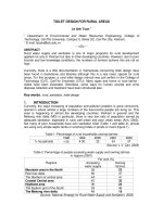
load) is in the direction of the shaft axis (see Fig. 1-1), while the radial load
component is in the direction normal to the shaft axis. In Fig. 1-1, an example of
a loaded shaft is presented. The reaction forces in helical gears have radial and
axial components. The component F
a
is in the axial direction, while all the other
components are radial loads. Examples of solved problems are included at the
end of this chapter. Certain bearings, such as conical roller bearings, shown in
Fig. 1-1, or angular ball bearings, can support radial as well as thrust forces.
Certain other bearings, however, such as hydrodynamic journal bearings, are
applied only for radial loads, while the hydrodynamic thrust bearing supports
FIG. 1-1 Load components on a shaft with helical gears.
Copyright 2003 by Marcel Dekker, Inc. All Rights Reserved.
only axial loads. A combination of radial and thrust bearings is often applied to
support the shaft in machinery.
1.1.2 Bearing Classi¢cation
Machines could not operate at high speed in their familiar way without some
means of reducing friction and the wear of moving parts. Several important
engineering inventions made it possible to successfully operate heavily loaded
shafts at high speed, including the rolling-element bearing and hydrodynamic,
hydrostatic, and magnetic bearings.
1. Rolling-element bearings are characterized by rolling motion, such as
in ball bearings or cylindrical rolling-element bearings. The advantage
of rolling motion is that it involves much less friction and wear, in
comparison to the sliding motion of regular sleeve bearings.
2. The term hydrodynamic bearing refers to a sleeve bearing or an
inclined plane-slider where the sliding plane floats on a thin film of
lubrication. The fluid film is maintained at a high pressure that supports
the bearing load and completely separates the sliding surfaces. The
lubricant can be fed into the bearing at atmospheric or higher pressure.
The pressure wave in the lubrication film is generated by hydrody-
namic action due to the rapid rotation of the journal. The fluid film acts
like a viscous wedge and generates high pressure and load-carrying
capacity. The sliding surface floats on the fluid film, and wear is
prevented.
3. In contrast to hydrodynamic bearing, hydrostatic bearing refers to a
configuration where the pressure in the fluid film is generated by an
external high-pressure pump. The lubricant at high pressure is fed into
the bearing recesses from an external pump through high-pressure
tubing. The fluid, under high pressure in the bearing recesses, carries
the load and separates the sliding surfaces, thus preventing high
friction and wear.
4. A recent introduction is the electromagnetic bearing. It is still in
development but has already been used in some unique applications.
The concept of operation is that a magnetic force is used to support the
bearing load. Several electromagnets are mounted on the bearing side
(stator poles). The bearing load capacity is generated by the magnetic
field between rotating laminators, mounted on the journal, and stator
poles, on the stationary bearing side. Active feedback control keeps the
journal floating without any contact with the bearing surface. The
advantage is that there is no contact between the sliding surfaces, so
wear is completely prevented as long as there is magnetic levitation.
Copyright 2003 by Marcel Dekker, Inc. All Rights Reserved.
Further description of the characteristics and applications of these bearings
is included in this and the following chapters.
1.2 DRY AND BOUNDARY LUBRICATION
BEARINGS
Whenever the load on the bearing is light and the shaft speed is low, wear is not a
critical problem and a sleeve bearing or plane-slider lubricated by a very thin
layer of oil (boundary lubrication) can be adequate. Sintered bronzes with
additives of other elements are widely used as bearing materials. Liquid or
solid lubricants are often inserted into the porosity of the material and make it
self-lubricated. However, in heavy-duty machinery—namely, bearings operating
for long periods of time under heavy load relative to the contact area and at high
speeds—better bearing types should be selected to prevent excessive wear rates
and to achieve acceptable bearing life. Bearings from the aforementioned list can
be selected, namely, rolling-element bearings or fluid film bearings.
In most applications, the sliding surfaces of the bearing are lubricated.
However, bearings with dry surfaces are used in unique situations where
lubrication is not desirable. Examples are in the food and pharmaceutical
industries, where the risk of contamination by the lubricant forbids its application.
The sliding speed, V , and the average pressure in the bearing, P, limit the use of
dry or boundary lubrication. For plastic and sintered bearing materials, a widely
accepted limit criterion is the product PV for each bearing material and
lubrication condition. This product is proportional to the amount of friction-
energy loss that is dissipated in the bearing as heat. This is in addition to limits on
the maximum sliding velocity and average pressure. For example, a self-
lubricated sintered bronze bearing has the following limits:
Surface velocity limit, V,is6m=s, or 1180 ft=min
Average surface-pressure limit, P, is 14 MPa, or 2000 psi
PV limit is 110,000 psi-ft=min, or 3:85 Â10
6
Pa-m=s
In comparison, bearings made of plastics have much lower PV limit. This is
because the plastics have a low melting point; in addition, the plastics are not
good conductors of heat, in comparison to metals. For these reasons, the PV limit
is kept at relatively low values, in order to prevent bearing failure by overheating.
For example, Nylon 6, which is widely used as a bearing material, has the
following limits as a bearing material:
Surface velocity limit, V,is5m=s
Average surface-pressure limit, P, is 6.9 MPa
PV limit is 105 Â10
3
Pa-m=s
Copyright 2003 by Marcel Dekker, Inc. All Rights Reserved.
Remark. In hydrodynamic lubrication, the symbol for surface velocity of
a rotating shaft is U, but for the PV product, sliding velocity V is traditionally
used.
Conversion to SI Units.
1 lbf=in:
2
ðpsiÞ¼6895 N=m
2
ðPaÞ
1ft=min ¼ 0:0051 m=s
1 psi-ft=min ¼ 6895 Â 0:0051 ¼ 35 Pa-m=s ¼ 35 Â10
À6
MPa-m=s
An example for calculation of the PV value in various cases is included at
the end of this chapter. The PV limit is much lower than that obtained by
multiplying the maximum speed and maximum average pressure due to the load
capacity. The reason is that the maximum PV is determined from considerations
of heat dissipation in the bearing, while the average pressure and maximum speed
can be individually of higher value, as long as the product is not too high. If the
maximum PV is exceeded, it would usually result in a faster-than-acceptable wear
rate.
1.3 HYDRODYNAMIC BEARING
An inclined plane-slider is shown in Fig. 1-2. It carries a load F and has
horizontal velocity, U, relative to a stationary horizontal plane surface. The plane-
slider is inclined at an angle a relative to the horizontal plane. If the surfaces were
dry, there would be direct contact between the two surfaces, resulting in
significant friction and wear. It is well known that friction and wear can be
reduced by lubrication. If a sufficient quantity of lubricant is provided and the
FIG. 1-2 Hydrodynamic lubrication of plane-slider.
Copyright 2003 by Marcel Dekker, Inc. All Rights Reserved.
sliding velocity is high, the surfaces would be completely separated by a very thin
lubrication film having the shape of a fluid wedge. In the case of complete
separation, full hydrodynamic lubrication is obtained. The plane-slider is inclined,
to form a converging viscous wedge of lubricant as shown in Fig. 1-2. The
magnitudes of h
1
and h
2
are very small, of the order of only a few micrometers.
The clearance shown in Fig. 1-2 is much enlarged.
The lower part of Fig. 1-2 shows the pressure distribution, p (pressure
wave), inside the thin fluid film. This pressure wave carries the slider and its load.
The inclined slider, floating on the lubricant, is in a way similar to water-skiing,
although the physical phenomena are not identical. The pressure wave inside the
lubrication film is due to the fluid viscosity, while in water-skiing it is due to the
fluid inertia. The generation of a pressure wave in hydrodynamic bearings can be
explained in simple terms, as follows: The fluid adheres to the solid surfaces and
is dragged into the thin converging wedge by the high shear forces due to the
motion of the plane-slider. In turn, high pressure must build up in the fluid film in
order to allow the fluid to escape through the thin clearances.
A commonly used bearing in machinery is the hydrodynamic journal
bearing, as shown in Fig. 1-3. Similar to the inclined plane-slider, it can support
a radial load without any direct contact between the rotating shaft (journal) and
the bearing sleeve. The viscous fluid film is shaped like a wedge due to the
eccentricity, e, of the centers of the journal relative to that of bearing bore. As
with the plane-slider, a pressure wave is generated in the lubricant, and a thin fluid
FIG. 1-3 Hydrodynamic journal bearing.
Copyright 2003 by Marcel Dekker, Inc. All Rights Reserved.
film completely separates the journal and bearing surfaces. Due to the hydro-
dynamic effect, there is low friction and there is no significant wear as long as a
complete separation is maintained between the sliding surfaces.
The pressure wave inside the hydrodynamic film carries the journal weight
together with the external load on the journal. The principle of operation is the
uneven clearance around the bearing formed by a small eccentricity, e, between
the journal and bearing centers, as shown in Fig. 1-3. The clearance is full of
lubricant and forms a thin fluid film of variable thickness. A pressure wave is
generated in the converging part of the clearance. The resultant force of the fluid
film pressure wave is the load-carrying capacity, W , of the bearing. For bearings
operating at steady conditions (constant journal speed and bearing load), the load-
carrying capacity is equal to the external load, F, on the bearing. But the two
forces of action and reaction act in opposite directions.
In a hydrodynamic journal bearing, the load capacity (equal in magnitude
to the bearing force) increases with the eccentricity, e, of the journal. Under
steady conditions, the center of the journal always finds its equilibrium point,
where the load capacity is equal to the external load on the journal. Figure 1-3
indicates that the eccentricity displacement, e, of the journal center, away from
the bearing center, is not in the vertical direction but at a certain attitude angle, f,
from the vertical direction. In this configuration, the resultant load capacity, due
to the pressure wave, is in the vertical direction, opposing the vertical external
force. The fluid film pressure is generated mostly in the converging part of the
clearance, and the attitude angle is required to allow the converging region to be
below the journal to provide the required lift force in the vertical direction and, in
this way, to support the external load.
In real machinery, there are always vibrations and disturbances that can
cause occasional contact between the surface asperities (surface roughness),
resulting in severe wear. In order to minimize this risk, the task of the engineer
is to design the hydrodynamic journal bearing so that it will operate with a
minimum lubrication-film thickness, h
n
, much thicker than the size of the surface
asperities. Bearing designers must keep in mind that if the size of the surface
asperities is of the order of magnitude of 1 micron, the minimum film thickness,
h
n
, should be 10–100 microns, depending on the bearing size and the level of
vibrations expected in the machine.
1.3.1 Disadvantages of Hydrodynamic Bearings
One major disadvantage of hydrodynamic bearings is that a certain minimum
speed is required to generate a full fluid film that completely separates the sliding
surfaces. Below that speed, there is mixed or boundary lubrication, with direct
contact between the asperities of the rubbing surfaces. For this reason, even if the
bearing is well designed and successfully operating at the high rated speed of the
Copyright 2003 by Marcel Dekker, Inc. All Rights Reserved.