Lập trình Vi Xử lý bằng ngôn ngữ C
Bạn đang xem bản rút gọn của tài liệu. Xem và tải ngay bản đầy đủ của tài liệu tại đây (2.65 MB, 142 trang )
I
Programming
Embedded
Systems I
A 10-week course, using C
40
39
38
37
36
35
34
1
2
3
4
5
6
7
‘8051’
8
9
10
33
32
31
30
29
28
27
26
25
24
11
12
13
14
15
16
17
18
19
20
23
22
21
P3.0
P1.7
RST
P1.6
P1.5
P1.4
P1.2
P1.3
P1.1
P1.0
VSS
XTL2
XTL1
P3.7
P3.6
P3.5
P3.3
P3.4
P3.2
P3.1
/ EA
P0.6
P0.7
P0.5
P0.4
P0.3
P0.1
P0.2
P0.0
VCC
P2.0
P2.2
P2.1
P2.3
P2.4
P2.5
P2.7
P2.6
/ PSEN
ALE
Michael J. Pont
University of Leicester
[v1.2]
II
Copyright © Michael J. Pont, 2002-2003
This document may be freely distributed and copied, provided that copyright notice at
the foot of each OHP page is clearly visible in all copies.
III
Seminar 1: “Hello, Embedded World” 1
Overview of this seminar 2
Overview of this course 3
By the end of the course … 4
Main course textbook 5
Why use C? 6
Pre-requisites! 7
The 8051 microcontroller 8
The “super loop” software architecture 9
Strengths and weaknesseses of “super loops” 10
Example: Central-heating controller 11
Reading from (and writing to) port pins 12
SFRs and ports 13
SFRs and ports 14
Creating and using sbit variables 15
Example: Reading and writing bytes 16
Creating “software delays” 17
Using the performance analyzer to test software delays 18
Strengths and weaknesses of software-only delays 19
Preparation for the next seminar 20
IV
Seminar 2: Basic hardware foundations (resets, oscillators and port I/O) 21
Review: The 8051 microcontroller 22
Review: Central-heating controller 23
Overview of this seminar 24
Oscillator Hardware 25
How to connect a crystal to a microcontroller 27
Oscillator frequency and machine cycle period 28
Keep the clock frequency as low as possible 29
Stability issues 30
Improving the stability of a crystal oscillator 31
Overall strengths and weaknesses 32
Reset Hardware 34
More robust reset circuits 35
Driving DC Loads 36
Use of pull-up resistors 38
Driving a low-power load without using a buffer 39
Using an IC Buffer 40
Example: Buffering three LEDs with a 74HC04 41
What is a multi-segment LED? 42
Driving a single digit 43
Preparation for the next seminar 44
V
Seminar 3: Reading Switches 45
Introduction 46
Review: Basic techniques for reading from port pins 47
Example: Reading and writing bytes (review) 48
Example: Reading and writing bits (simple version) 49
Example: Reading and writing bits (generic version) 51
The need for pull-up resistors 56
The need for pull-up resistors 57
The need for pull-up resistors 58
Dealing with switch bounce 59
Example: Reading switch inputs (basic code) 61
Example: Counting goats 68
Conclusions 74
Preparation for the next seminar 75
VI
Seminar 4: Adding Structure to Your Code 77
Introduction 78
Object-Oriented Programming with C 79
Example of “O-O C” 82
The Project Header (Main.H) 85
The Port Header (Port.H) 92
Re-structuring a “Hello World” example 96
Example: Re-structuring the Goat-Counting Example 104
Preparation for the next seminar 114
VII
Seminar 5: Meeting Real-Time Constraints 115
Introduction 116
Creating “hardware delays” 118
The TCON SFR 119
The TMOD SFR 120
Two further registers 121
Example: Generating a precise 50 ms delay 122
Example: Creating a portable hardware delay 126
The need for ‘timeout’ mechanisms - example 129
Creating loop timeouts 130
Example: Testing loop timeouts 132
Example: A more reliable switch interface 134
Creating hardware timeouts 135
Conclusions 137
Preparation for the next seminar 138
VIII
Seminar 6: Creating an Embedded Operating System 139
Introduction 140
Timer-based interrupts (the core of an embedded OS) 144
The interrupt service routine (ISR) 145
Automatic timer reloads 146
Introducing sEOS 147
Introducing sEOS 148
Tasks, functions and scheduling 153
Setting the tick interval 154
Saving power 157
Using sEOS in your own projects 158
Is this approach portable? 159
Example: Milk pasteurization 160
Conclusions 174
Preparation for the next seminar 175
IX
Seminar 7: Multi-State Systems and Function Sequences 177
Introduction 178
Implementing a Multi-State (Timed) system 180
Example: Traffic light sequencing 181
Example: Animatronic dinosaur 189
Implementing a Multi-State (Input/Timed) system 195
Example: Controller for a washing machine 197
Conclusions 208
Preparation for the next seminar 209
X
Seminar 8: Using the Serial Interface 211
Overview of this seminar 212
What is ‘RS-232’? 213
Basic RS-232 Protocol 214
Asynchronous data transmission and baud rates 215
RS-232 voltage levels 216
The software architecture 217
Overview 218
Using the on-chip U(S)ART for RS-232 communications 219
Serial port registers 220
Baud rate generation 221
Why use 11.0592 MHz crystals? 222
PC Software 223
What about printf()? 224
RS-232 and 8051: Overall strengths and weaknesses 225
Example: Displaying elapsed time on a PC 226
Example: Data acquisition 235
Conclusions 239
Preparation for the next seminar 240
XI
Seminar 9: Case Study: Intruder Alarm System 241
Introduction 242
System Operation 243
Key software components used in this example 244
Running the program 245
The software 246
Extending and modifying the system 260
Conclusions 261
XII
Seminar 10: Case Study: Controlling a Mobile Robot 263
Overview 264
What can the robot do? 265
The robot brain 266
How does the robot move? 267
Pulse-width modulation 268
Software PWM 269
The resulting code 270
More about the robot 271
Conclusions 272
COPYRIGHT © MICHAEL J. PONT, 2001-2003. Contains material from:
Pont, M.J. (2002) “Embedded C”, Addison-Wesley.
PES I - 1
Seminar 1:
“Hello, Embedded
World”
B
E
C
5.5V, 0.3A lamp
ZTX751
4V - 6V (battery)
10 KΩ
10 µF
4 MHz
20
19
18
17
16
15
14
1
2
3
4
5
6
7
Atmel 2051
8
9
10
13
12
11
GND
P3.4
P3.5
P3.3
P3.2
XTL1
P3.1
XTL2
P3.0
RST
P3.7
P1.1
P1.0
P1.2
P1.3
P1.4
P1.6
P1.5
P1.7
VCC
40
39
38
37
36
35
34
1
2
3
4
5
6
7
‘8051’
8
9
10
33
32
31
30
29
28
27
26
25
24
11
12
13
14
15
16
17
18
19
20
23
22
21
P3.0
P1.7
RST
P1.6
P1.5
P1.4
P1.2
P1.3
P1.1
P1.0
VSS
XTL2
XTL1
P3.7
P3.6
P3.5
P3.3
P3.4
P3.2
P3.1
/ EA
P0.6
P0.7
P0.5
P0.4
P0.3
P0.1
P0.2
P0.0
VCC
P2.0
P2.2
P2.1
P2.3
P2.4
P2.5
P2.7
P2.6
/ PSEN
ALE
COPYRIGHT © MICHAEL J. PONT, 2001-2003. Contains material from:
Pont, M.J. (2002) “Embedded C”, Addison-Wesley.
PES I - 2
Overview of this seminar
This introductory seminar will:
• Provide an overview of this course
• Introduce the 8051 microcontroller
• Present the “Super Loop” software architecture
• Describe how to use port pins
• Consider how you can generate delays (and why you might
need to).
COPYRIGHT © MICHAEL J. PONT, 2001-2003. Contains material from:
Pont, M.J. (2002) “Embedded C”, Addison-Wesley.
PES I - 3
Overview of this course
This course is concerned with the implementation of software (and
a small amount of hardware) for embedded systems constructed
using a single microcontroller.
The processors examined in detail are from the 8051 family
(including both ‘Standard’ and ‘Small’ devices).
All programming is in the ‘C’ language.
COPYRIGHT © MICHAEL J. PONT, 2001-2003. Contains material from:
Pont, M.J. (2002) “Embedded C”, Addison-Wesley.
PES I - 4
By the end of the course …
By the end of the course, you will be able to:
1. Design software for single-processor embedded applications
based on small, industry standard, microcontrollers;
2. Implement the above designs using a modern, high-level
programming language (‘C’), and
3. Begin to understand issues of reliability and safety and how
software design and programming decisions may have a
positive or negative impact in this area.
COPYRIGHT © MICHAEL J. PONT, 2001-2003. Contains material from:
Pont, M.J. (2002) “Embedded C”, Addison-Wesley.
PES I - 5
Main course textbook
Throughout this course, we will be making heavy use of this book:
Embedded C
by Michael J. Pont (2002)
Addison-Wesley
[ISBN: 0-201-79523X]
For further information about this book, please see:
/>COPYRIGHT © MICHAEL J. PONT, 2001-2003. Contains material from:
Pont, M.J. (2002) “Embedded C”, Addison-Wesley.
PES I - 6
Why use C?
• It is a ‘mid-level’, with ‘high-level’ features (such as support
for functions and modules), and ‘low-level’ features (such as
good access to hardware via pointers);
• It is very efficient;
• It is popular and well understood;
• Even desktop developers who have used only Java or C++
can soon understand C syntax;
• Good, well-proven compilers are available for every
embedded processor (8-bit to 32-bit or more);
• Experienced staff are available;
• Books, training courses, code samples and WWW sites
discussing the use of the language are all widely available.
Overall, C may not be an
perfect
language for developing embedded
systems, but it is a good choice (and is unlikely that a ‘perfect’ language
will ever be created).
COPYRIGHT © MICHAEL J. PONT, 2001-2003. Contains material from:
Pont, M.J. (2002) “Embedded C”, Addison-Wesley.
PES I - 7
Pre-requisites!
• Throughout this course, it will be assumed that you have had
previous programming experience: this might be in - for
example - Java or C++.
• For most people with such a background, “getting to grips”
with C is straightforward.
COPYRIGHT © MICHAEL J. PONT, 2001-2003. Contains material from:
Pont, M.J. (2002) “Embedded C”, Addison-Wesley.
PES I - 8
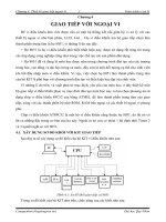
The 8051 microcontroller
40
39
38
37
36
35
34
1
2
3
4
5
6
7
‘8051’
8
9
10
33
32
31
30
29
28
27
26
25
24
11
12
13
14
15
16
17
18
19
20
23
22
21
P3.0
P1.7
RST
P1.6
P1.5
P1.4
P1.2
P1.3
P1.1
P1.0
VSS
XTL2
XTL1
P3.7
P3.6
P3.5
P3.3
P3.4
P3.2
P3.1
/ EA
P0.6
P0.7
P0.5
P0.4
P0.3
P0.1
P0.2
P0.0
VCC
P2.0
P2.2
P2.1
P2.3
P2.4
P2.5
P2.7
P2.6
/ PSEN
ALE
Typical features of a modern 8051:
• Thirty-two input / output lines.
• Internal data (RAM) memory - 256 bytes.
• Up to 64 kbytes of ROM memory (usually flash)
• Three 16-bit timers / counters
• Nine interrupts (two external) with two priority levels.
• Low-power Idle and Power-down modes.
The different members of this family are suitable for everything from
automotive and aerospace systems to TV “remotes”.
COPYRIGHT © MICHAEL J. PONT, 2001-2003. Contains material from:
Pont, M.J. (2002) “Embedded C”, Addison-Wesley.
PES I - 9
The “super loop” software architecture
Problem
What is the minimum software environment you need to create an
embedded C program?
Solution
void main(void)
{
/* Prepare for task X */
X_Init();
while(1)
/* 'for ever' (Super Loop) */
{
X();
/* Perform the task */
}
}
Crucially, the ‘super loop’, or ‘endless loop’, is required because we
have no operating system to return to: our application will keep looping
until the system power is removed.
COPYRIGHT © MICHAEL J. PONT, 2001-2003. Contains material from:
Pont, M.J. (2002) “Embedded C”, Addison-Wesley.
PES I - 10
Strengths and weaknesseses of “super loops”
The main strength of Super Loop systems is their simplicity. This
makes them (comparatively) easy to build, debug, test and maintain.
Super Loops are highly efficient: they have minimal hardware
resource implications.
Super Loops are highly portable.
BUT:
If your application requires accurate timing (for example, you need to
acquire data precisely every 2 ms), then this framework will not
provide the accuracy or flexibility you require.
The basic Super Loop operates at ‘full power’ (normal operating
mode) at all times. This may not be necessary in all applications, and
can have a dramatic impact on system power consumption.
[As we will see in Seminar 6, a scheduler can address these
problems.]
COPYRIGHT © MICHAEL J. PONT, 2001-2003. Contains material from:
Pont, M.J. (2002) “Embedded C”, Addison-Wesley.
PES I - 11
Example: Central-heating controller
Central
heating
controller
Boiler
Temperature
sensor
Temperature
dial
void main(void)
{
/* Init the system */
C_HEAT_Init();
while(1)
/* 'for ever' (Super Loop) */
{
/* Find out what temperature the user requires
(via the user interface) */
C_HEAT_Get_Required_Temperature();
/* Find out what the current room temperature is
(via temperature sensor) */
C_HEAT_Get_Actual_Temperature();
/* Adjust the gas burner, as required */
C_HEAT_Control_Boiler();
}
}
COPYRIGHT © MICHAEL J. PONT, 2001-2003. Contains material from:
Pont, M.J. (2002) “Embedded C”, Addison-Wesley.
PES I - 12
Reading from (and writing to) port pins
Problem
How do you write software to read from and /or write to the ports
on an (8051) microcontroller?
Background
The Standard 8051s have four 8-bit ports.
All of the ports are bidirectional: that is, they may be used for both
input and output.
COPYRIGHT © MICHAEL J. PONT, 2001-2003. Contains material from:
Pont, M.J. (2002) “Embedded C”, Addison-Wesley.
PES I - 13
SFRs and ports
Control of the 8051 ports through software is carried out using what
are known as ‘special function registers’ (SFRs).
Physically, the SFR is a area of memory in internal RAM:
• P0 is at address 0x80
• P1 at address 0x90
• P2 at address 0xA0
• P3 at address 0xB0
NOTE: 0x means that the number format is HEXADECIMAL
- see Embedded C, Chapter 2.
COPYRIGHT © MICHAEL J. PONT, 2001-2003. Contains material from:
Pont, M.J. (2002) “Embedded C”, Addison-Wesley.
PES I - 14
SFRs and ports
A typical SFR header file for an 8051 family device will contain the
lines:
sfr P0 = 0x80;
sfr P1 = 0x90;
sfr P2 = 0xA0;
sfr P3 = 0xB0;
Having declared the SFR variables, we can write to the ports in a
straightforward manner. For example, we can send some data to
Port 1 as follows:
unsigned char Port_data;
Port_data = 0x0F;
P1 = Port_data;
/* Write 00001111 to Port 1 */
Similarly, we can read from (for example) Port 1 as follows:
unsigned char Port_data;
P1 = 0xFF; /* Set the port to ‘read mode’ */
Port_data = P1; /* Read from the port */
Note that, in order to read from a pin, we need to ensure that the last
thing written to the pin was a ‘1’.
COPYRIGHT © MICHAEL J. PONT, 2001-2003. Contains material from:
Pont, M.J. (2002) “Embedded C”, Addison-Wesley.
PES I - 15
Creating and using
sbit
variables
To write to a single pin, we can make use of an sbit variable in the
Keil (C51) compiler to provide a finer level of control.
Here’s a clean way of doing this:
#define LED_PORT P3
#define LED_ON 0 /* Easy to change the logic here */
#define LED_OFF 1
sbit Warning_led = LED_PORT^0;
/* LED is connected to pin 3.0 */
Warning_led = LED_ON;
/* delay */
Warning_led = LED_OFF;
/* delay */
Warning_led = LED_ON;
/* etc */
COPYRIGHT © MICHAEL J. PONT, 2001-2003. Contains material from:
Pont, M.J. (2002) “Embedded C”, Addison-Wesley.
PES I - 16
Example: Reading and writing bytes
The input port
The output port
void main (void)
{
unsigned char Port1_value;
/* Must set up P1 for reading */
P1 = 0xFF;
while(1)
{
/* Read the value of P1 */
Port1_value = P1;
/* Copy the value to P2 */
P2 = Port1_value;
}
}
COPYRIGHT © MICHAEL J. PONT, 2001-2003. Contains material from:
Pont, M.J. (2002) “Embedded C”, Addison-Wesley.
PES I - 17
Creating “software delays”
Problem
How do you create a simple delay without using any hardware
(timer) resources?
Solution
Loop_Delay()
{
unsigned int x,y;
for (x=0; x <= 65535; x++)
{
y++;
}
}
Longer_Loop_Delay()
{
unsigned int x, y, z;
for (x=0; x<=65535; x++)
{
for (y=0; y<=65535; y++);
{
z++;
}
}
}
COPYRIGHT © MICHAEL J. PONT, 2001-2003. Contains material from:
Pont, M.J. (2002) “Embedded C”, Addison-Wesley.
PES I - 18
Using the performance analyzer to test software delays
COPYRIGHT © MICHAEL J. PONT, 2001-2003. Contains material from:
Pont, M.J. (2002) “Embedded C”, Addison-Wesley.
PES I - 19
Strengths and weaknesses of software-only delays
SOFTWARE DELAY can be used to produce very short delays.
SOFTWARE DELAY requires no hardware timers.
SOFTWARE DELAY will work on any microcontroller.
BUT:
It is very difficult to produce precisely timed delays.
The loops must be re-tuned if you decide to use a different processor,
change the clock frequency, or even change the compiler optimisation
settings.
COPYRIGHT © MICHAEL J. PONT, 2001-2003. Contains material from:
Pont, M.J. (2002) “Embedded C”, Addison-Wesley.
PES I - 20
Preparation for the next seminar
In the lab session associated with this seminar, you will use a
hardware simulator to try out the techniques discussed here. This
will give you a chance to focus on the software aspects of
embedded systems, without dealing with hardware problems.
In the next seminar, we will prepare to create your first test systems
on “real hardware”.
Please read Chapters 1, 2 and 3
before the next seminar
COPYRIGHT © MICHAEL J. PONT, 2001-2003. Contains material from:
Pont, M.J. (2002) “Embedded C”, Addison-Wesley.
PES I - 21
Seminar 2:
Basic hardware
foundations (resets,
oscillators and port
I/O)
Atmel
89C52
Vcc
RESET
GND
Vcc
EA
30 pF ±10
30 pF ±10
XTAL 2
XTAL 1
DS1812
12 MHz
COPYRIGHT © MICHAEL J. PONT, 2001-2003. Contains material from:
Pont, M.J. (2002) “Embedded C”, Addison-Wesley.
PES I - 22
Review: The 8051 microcontroller
40
39
38
37
36
35
34
1
2
3
4
5
6
7
‘8051’
8
9
10
33
32
31
30
29
28
27
26
25
24
11
12
13
14
15
16
17
18
19
20
23
22
21
P3.0
P1.7
RST
P1.6
P1.5
P1.4
P1.2
P1.3
P1.1
P1.0
VSS
XTL2
XTL1
P3.7
P3.6
P3.5
P3.3
P3.4
P3.2
P3.1
/ EA
P0.6
P0.7
P0.5
P0.4
P0.3
P0.1
P0.2
P0.0
VCC
P2.0
P2.2
P2.1
P2.3
P2.4
P2.5
P2.7
P2.6
/ PSEN
ALE
Typical features of a modern 8051:
• Thirty-two input / output lines.
• Internal data (RAM) memory - 256 bytes.
• Up to 64 kbytes of ROM memory (usually flash)
• Three 16-bit timers / counters
• Nine interrupts (two external) with two priority levels.
• Low-power Idle and Power-down modes.
The different members of this family are suitable for everything from
automotive and aerospace systems to TV “remotes”.
COPYRIGHT © MICHAEL J. PONT, 2001-2003. Contains material from:
Pont, M.J. (2002) “Embedded C”, Addison-Wesley.
PES I - 23
Review: Central-heating controller
Central
heating
controller
Boiler
Temperature
sensor
Temperature
dial
void main(void)
{
/* Init the system */
C_HEAT_Init();
while(1)
/* 'for ever' (Super Loop) */
{
/* Find out what temperature the user requires
(via the user interface) */
C_HEAT_Get_Required_Temperature();
/* Find out what the current room temperature is
(via temperature sensor) */
C_HEAT_Get_Actual_Temperature();
/* Adjust the gas burner, as required */
C_HEAT_Control_Boiler();
}
}
COPYRIGHT © MICHAEL J. PONT, 2001-2003. Contains material from:
Pont, M.J. (2002) “Embedded C”, Addison-Wesley.
PES I - 24
Overview of this seminar
This seminar will:
• Consider the techniques you need to construct your first
“real” embedded system (on a breadboard).
Specifically, we’ll look at:
• Oscillator circuits
• Reset circuits
• Controlling LEDs
COPYRIGHT © MICHAEL J. PONT, 2001-2003. Contains material from:
Pont, M.J. (2002) “Embedded C”, Addison-Wesley.
PES I - 25
Oscillator Hardware
• All digital computer systems are driven by some form of
oscillator circuit.
• This circuit is the ‘heartbeat’ of the system and is crucial to
correct operation.
For example:
• If the oscillator fails, the system will not function at all.
• If the oscillator runs irregularly, any timing calculations
performed by the system will be inaccurate.
COPYRIGHT © MICHAEL J. PONT, 2001-2003. Contains material from:
Pont, M.J. (2002) “Embedded C”, Addison-Wesley.
PES I - 26
CRYSTAL OSCILLATOR
Crystals may be used to generate a popular form of oscillator circuit
known as a Pierce oscillator.
C
Crystal
R
JFET
L
Vcc
Oscillator output
(to microcontroller)
• A variant of the Pierce oscillator is common in the 8051
family. To create such an oscillator, most of the components
are included on the microcontroller itself.
• The user of this device must generally only supply the
crystal and two small capacitors to complete the oscillator
implementation.
COPYRIGHT © MICHAEL J. PONT, 2001-2003. Contains material from:
Pont, M.J. (2002) “Embedded C”, Addison-Wesley.
PES I - 27
How to connect a crystal to a microcontroller
C
C
8051-family
microcontroller
GND
XTAL
XTAL
In the absence of specific information, a capacitor value of
30 pF will perform well in most circumstances.
COPYRIGHT © MICHAEL J. PONT, 2001-2003. Contains material from:
Pont, M.J. (2002) “Embedded C”, Addison-Wesley.
PES I - 28
Oscillator frequency and machine cycle period
• In the original members of the 8051 family, the machine
cycle takes twelve oscillator periods.
• In later family members, such as the Infineon C515C, a
machine cycle takes six oscillator periods; in more recent
devices such as the Dallas 89C420, only one oscillator
period is required per machine cycle.
• As a result, the later members of the family operating at the
same clock frequency execute instructions much more
rapidly.
COPYRIGHT © MICHAEL J. PONT, 2001-2003. Contains material from:
Pont, M.J. (2002) “Embedded C”, Addison-Wesley.
PES I - 29
Keep the clock frequency as low as possible
Many developers select an oscillator / resonator frequency that is at
or near the maximum value supported by a particular device.
This can be a mistake:
• Many application do not require the levels of performance
that a modern 8051 device can provide.
• The electromagnetic interference (EMI) generated by a
circuit increases with clock frequency.
• In most modern (CMOS-based) 8051s, there is an almost
linear relationship between the oscillator frequency and the
power-supply current. As a result, by using the lowest
frequency necessary it is possible to reduce the power
requirement: this can be useful in many applications.
• When accessing low-speed peripherals (such as slow
memory, or LCD displays), programming and hardware
design can be greatly simplified - and the cost of peripheral
components, such as memory latches, can be reduced - if the
chip is operating more slowly.
In general, you should operate at the lowest possible oscillator
frequency compatible with the performance needs of your application.
COPYRIGHT © MICHAEL J. PONT, 2001-2003. Contains material from:
Pont, M.J. (2002) “Embedded C”, Addison-Wesley.
PES I - 30
Stability issues
• A key factor in selecting an oscillator for your system is the
issue of oscillator stability. In most cases, oscillator stability
is expressed in figures such as ‘±20 ppm’: ‘20 parts per
million’.
• To see what this means in practice, consider that there are
approximately 32 million seconds in a year. In every million
seconds, your crystal may gain (or lose) 20 seconds. Over
the year, a clock based on a 20 ppm crystal may therefore
gain (or lose) about 32 x 20 seconds, or around 10 minutes.
Standard quartz crystals are typically rated from ±10 to ±100 ppm, and
so may gain (or lose) from around 5 to 50 minutes per year.
COPYRIGHT © MICHAEL J. PONT, 2001-2003. Contains material from:
Pont, M.J. (2002) “Embedded C”, Addison-Wesley.
PES I - 31
Improving the stability of a crystal oscillator
• If you want a general crystal-controlled embedded system to
keep accurate time, you can choose to keep the device in an
oven (or fridge) at a fixed temperature, and fine-tune the
software to keep accurate time. This is, however, rarely
practical.
• ‘Temperature Compensated Crystal Oscillators’ (TCXOs)
are available that provide - in an easy-to-use package - a
crystal oscillator, and circuitry that compensates for changes
in temperature. Such devices provide stability levels of up to
±0.1 ppm (or more): in a clock circuit, this should gain or
lose no more than around 1 minute every 20 years.
TCXOs can cost in excess of $100.00 per unit
• One practical alternative is to determine the temperature-
frequency characteristics for your chosen crystal, and include
this information in your application.
For the cost of a small temperature sensor (around $2.00),
you can keep track of the temperature and adjust the timing
as required.
COPYRIGHT © MICHAEL J. PONT, 2001-2003. Contains material from:
Pont, M.J. (2002) “Embedded C”, Addison-Wesley.
PES I - 32
Overall strengths and weaknesses
Crystal oscillators are stable. Typically ±20-100 ppm = ±50 mins per
year (up to ~1 minute / week).
The great majority of 8051-based designs use a variant of the simple
crystal-based oscillator circuit presented here: developers are
therefore familiar with crystal-based designs.
Quartz crystals are available at reasonable cost for most common
frequencies. The only additional components required are usually two
small capacitors. Overall, crystal oscillators are more expensive than
ceramic resonators.
BUT:
Crystal oscillators are susceptible to vibration.
The stability falls with age.
COPYRIGHT © MICHAEL J. PONT, 2001-2003. Contains material from:
Pont, M.J. (2002) “Embedded C”, Addison-Wesley.
PES I - 33
CERAMIC RESONATOR
Overall strengths and weaknesses
Cheaper than crystal oscillators.
Physically robust: less easily damage by physical vibration (or
dropped equipment, etc) than crystal oscillator.
Many resonators contain in-built capacitors, and can be used without
any external components.
Small size. About half the size of crystal oscillator.
BUT:
Comparatively low stability: not general appropriate for use where
accurate timing (over an extended period) is required. Typically ±5000
ppm = ±2500 min per year (up to ~50 minutes / week).
COPYRIGHT © MICHAEL J. PONT, 2001-2003. Contains material from:
Pont, M.J. (2002) “Embedded C”, Addison-Wesley.
PES I - 34
Reset Hardware
• The process of starting any microcontroller is a non-trivial
one.
• The underlying hardware is complex and a small,
manufacturer-defined, ‘reset routine’ must be run to place
this hardware into an appropriate state before it can begin
executing the user program. Running this reset routine takes
time, and requires that the microcontroller’s oscillator is
operating.
• An RC reset circuit is usually the simplest way of controlling
the reset behaviour.
Example:
30 pF ±10
30 pF ±10
AT89C2051
Vcc
RESET
GND
Vcc
10 K
10 uF
XTAL 2
XTAL 1
COPYRIGHT © MICHAEL J. PONT, 2001-2003. Contains material from:
Pont, M.J. (2002) “Embedded C”, Addison-Wesley.
PES I - 35
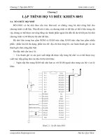
More robust reset circuits
Example:
Atmel
89C52
Vcc
RESET
GND
Vcc
EA
30 pF ±10
30 pF ±10
XTAL 2
XTAL 1
DS1812
12 MHz
COPYRIGHT © MICHAEL J. PONT, 2001-2003. Contains material from:
Pont, M.J. (2002) “Embedded C”, Addison-Wesley.
PES I - 36
Driving DC Loads
• The port pins on a typical 8051 microcontroller can be set at
values of either 0V or 5V (or, in a 3V system, 0V and 3V)
under software control.
• Each pin can typically sink (or source) a current of around
10 mA.
• The total current we can source or sink per microcontroller
(all 32 pins, where available) is typically 70 mA or less.
COPYRIGHT © MICHAEL J. PONT, 2001-2003. Contains material from:
Pont, M.J. (2002) “Embedded C”, Addison-Wesley.
PES I - 37
NAKED LED
Logic 0 (0v)
to light LED
Vcc
R
led
diode
diodecc
led
I
VV
R
−
=
8051 Device
PX.Y
Connecting a single LED directly to a microcomputer port is
usually possible.
• Supply voltage, V
cc
= 5V,
• LED forward voltage, V
diode
= 2V,
• Required diode current, I
diode
= 15 mA (note that the data
sheet for your chosen LED will provide this information).
This gives a required R value of 200
Ω.
COPYRIGHT © MICHAEL J. PONT, 2001-2003. Contains material from:
Pont, M.J. (2002) “Embedded C”, Addison-Wesley.
PES I - 38
Use of pull-up resistors
To adapt circuits for use on pins without internal pull-up resistors is
straightforward: you simply need to add an external pull-up resistor:
Logic 0
to light LED
Vcc
R
led
8051 Device
PX.Y
R
pull-up
The value of the pull-up resistor should be between 1K and 10K.
This requirement applies to all of the examples on this course.
NOTE:
This is usually only necessary on Port 0
(see Seminar 3 for further details).