Tài liệu Handbook of Machine Design P39 doc
Bạn đang xem bản rút gọn của tài liệu. Xem và tải ngay bản đầy đủ của tài liệu tại đây (314.29 KB, 9 trang )
CHAPTER
33
SPUR
GEARS
Joseph
E.
Shigley
Professor
Emeritus
The
University
of
Michigan
Ann
Arbor,
Michigan
33.1
DEFINITIONS
/
33.1
33.2
TOOTH
DIMENSIONS
AND
STANDARDS
/
33.4
33.3
FORCE
ANALYSIS
/
33.5
33.4
FUNDAMENTAL
AGMA
RATING
FORMULAS
/
33.6
33.7
DEFINITIONS
Spur
gears
are
used
to
transmit rotary motion between parallel
shafts.
They
are
cylindrical,
and the
teeth
are
straight
and
parallel
to the
axis
of
rotation.
The
pinion
is the
smaller
of two
mating gears;
the
larger
is
called
the
gear
or the
wheel.
The
pitch
circle,
B in
Fig.
33.1,
is a
theoretical circle upon which
all
calculations
are
based.
The
operating
pitch
circles
of a
pair
of
gears
in
mesh
are
tangent
to
each other.
The
circular
pitch,
p in
Fig. 33.1,
is the
distance, measured
on the
theoretical pitch
circle,
from
a
point
on one
tooth
to a
corresponding point
on an
adjacent
tooth.
The
circular
pitch
is
measured
in
inches
or in
millimeters. Note,
in
Fig. 33.1,
that
the
cir-
cular pitch
is the sum of the
tooth thickness
t and the
width
of
space.
The
pitch
diameter,
d for the
pinion
and D for the
gear,
is the
diameter
of the
pitch
circle;
it is
measured
in
inches
or in
millimeters.
The
module
m is the
ratio
of the
theoretical pitch diameter
to the
number
of
teeth
N.
The
module
is the
metric index
of
tooth sizes
and is
always given
in
millimeters.
The
diametral
pitch
P
d
is the
ratio
of the
number
of
teeth
on a
gear
to the
theo-
retical pitch diameter.
It is the
index
of
tooth size when U.S. customary units
are
used
and
is
expressed
as
teeth
per
inch.
The
addendum
a is the
radial distance between
the top
land
F and the
pitch circle
B in
Fig.
33.1.
The
dedendum
b is the
radial distance between
the
pitch circle
B and
the
root
circle
D in
Fig. 33.1.
The
whole
depth
h
t
is the sum of the
addendum
and
dedendum.
The
clearance circle
C in
Fig.
33.1
is
tangent
to the
addendum circle
of the
mating
gear.
The
distance
from
the
clearance circle
to the
bottom land
is
called
the
clearance
c.
Backlash
is the
amount
by
which
the
width
of a
tooth space exceeds
the
thickness
of
the
engaging tooth measured
on the
pitch circle.
Undercutting
(see
distance
u in
Fig.
33.1)
occurs under certain conditions when
a
small
number
of
teeth
are
used
in
cutting
a
gear.
Table
33.1
lists
all the
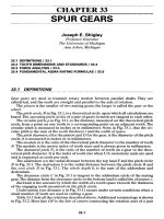
relations described above. Additional terminology
is
shown
in
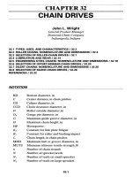
Fig. 33.2.
Here
line
OP is the
line
of
centers
connecting
the
rotation
axes
of a
pair
FIGURE
33.1
Terminology
of
gear teeth.
A,
addendum
circle;
B,
pitch circle;
C
9
clearance cir-
cle;
D,
dedendum
circle;
E,
bottom land;
F, top
land;
G, flank; H,
face;
a =
addendum distance;
b =
dedendum distance;
c =
clearance
distance;/?
=
circular pitch;
t =
tooth thickness;
u =
under-
cut
distance.
of
meshing gears. Line
E is the
pressure
line,
and the
angle
§
is the
pressure
angle.
The
resultant force vector between
a
pair
of
operating gears acts along this line.
The
pressure line
is
tangent
to
both
base
circles
C at
points
E The
operating diam-
eters
of the
pitch circles depend
on the
center distance used
in
mounting
the
gears,
but
the
base circle diameters
are
constant
and
depend only
on how the
tooth forms were
generated, because they
form
the
base
or the
starting point
of the
involute profile.
TABLE
33.1 Basic Formulas
for
Spur Gears
Equation
Quantity
desired
Formula
number
N
Diametral
pitch
P
d
P
d
=
—
(33.1)
a
Module
m
m
=
-
(33.2)
N
Circular
pitch
p p =
^-
=
irm
(33.3)
TV
Pitch
diameter,
d or D d = —
=
mN
(33.4)
^d
PARALLEL
FIGURE
33.2 Layout
drawing
of a
pair
of
spur gears
in
mesh.
The
pinion
is the
driver
and
rotates clockwise about
the
axis
at O. A,
addendum circles;
B,
pitch circles;
C,
base circles;
D,
dedendum
circles;
E,
pressure line;
F,
tangent points;
P,
pitch point;
a,
initial point
of
contact;
b,
final
point
of
contact.
Line
aPb is the
line
of
action. Point
a is the
initial
point
of
contact. This point
is
located
at the
intersection
of the
addendum circle
of the
gear with
the
pressure line.
Should point
a
occur
on the
other side
of
point
F on the
pinion base circle,
the
pin-
ion flank
would
be
undercut during generation
of the
profile.
Point
b of
Fig. 33.2
is the
final
point
of
contact.
This point
is
located
at the
inter-
section
of the
addendum circle
of the
pinion with
the
pressure line.
For no
under-
cutting
of the
gear teeth, point
b
must
be
located between
the
pitch point
P and
point
F on the
base circle
of the
gear.
Line
aP
represents
the
approach
phase
of
tooth
contact; line
Pb is the
recess
phase. Tooth contact
is a
sliding contact throughout
the
line
of
action except
for an
instant
at P
when contact
is
pure rolling.
The
nature
of the
sliding
is
quite
different
during
the
approach action
and the
recess action;
and
bevel-gear teeth,
for
example,
are
generated
to
obtain more
recess
action, thus reducing wear.
Instead
of
using
the
theoretical pitch circle
as an
index
of
tooth size,
the
base cir-
cle,
which
is a
more
fundamental
distance,
can be
used.
The
result
is
called
the
base
pitch
p
b
.
It is
related
to the
circular pitch
p by the
equation
p
b
=pcosty
(33.5)
If,
in
Fig. 33.2,
the
distance
from
a to b
exactly equals
the
base pitch, then, when
one
pair
of
teeth
are
just
beginning contact
at a, the
preceding pair
will
be
leaving
contact
at b.
Thus,
for
this special condition,
there
is
never more
or
less than
one
pair
of
teeth
in
contact.
If the
distance
ab is
greater than
the
base pitch
but
less than twice
as
much, then when
a
pair
of
teeth come into contact
at a,
another pair
of
teeth will
still
be in
contact somewhere along
the
line
of
action
ab.
Because
of the
nature
of
this
tooth action, usually
one or two
pairs
of
teeth
in
contact,
a
useful
criterion
of
tooth action, called
the
contact
ratio
m
c)
can be
defined.
The
formula
is
m
c
=
^-
(33.6)
Pb
where
L
ab
=
distance
ab, the
length
of the
line
of
action.
Do not
confuse
the
contact
ratio
m
c
with
the
module
m.
33.2
TOOTHDIMENSIONSANDSTANDARDS
The
American Gear Manufacturer's Association (AGMA) publishes much valuable
reference
data.
f
The
details
on
nomenclature, definitions,
and
tooth proportions
for
spur
gears
can be
found
in
ANSI/AGMA
201.2
and
1012-F90.
Table 33.2 contains
the
most
used tooth proportions.
The hob tip
radius
r
f
varies with
different
cutters;
0.300/P
rf
or
0.300m
is the
usual value. Tables
33.3
and
33.4
list
the
modules
and
pitches
in
general use. Cutting tools
can be
obtained
for all
these sizes.
f
See
Chap.
35 for a
special note
on
AGMA.
TABLE
33.2
Standard
and
Commonly Used Tooth Systems
for
Spur Gears
Tooth
system
Pressure
angle
0,
deg
Addendum
a
Dedendum
b
Full
depth
20
l/P
d
or\m
1.25/^or
.25m
\.3S/P
d
or
.35m
221
i/P
d
or\m
\.25/P
d
or
.25m
1.35//»/
or
.35m
25
\/P
d
or\m
\.25/P
d
or
.25m
1.35/P,
or
.35m
Stub
20
0.8//>/
or
0.8m
\/P
d
or 1 m
TABLE
33.3
Diametral Pitches
in
General
Use
Coarse
pitch
2,
21
2J,
3, 4, 6, 8, 10, 12, 16
Fine
pitch
20, 24, 32, 40, 48, 64, 96,
120, 150,
200
TABLE
33.4
Modules
in
General
Use
Preferred
1,
1.25, 1.5,
2,
2.5,
3, 4, 5, 6, 8, 10, 12, 16, 20, 25, 32, 40, 50
Next choice 1.125, 1.375, 1.75,
2.25, 2.75, 3.5, 4.5, 5.5,
7, 9,
11,
14, 18, 22, 28, 36, 45
33.3
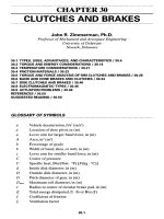
FORCEANALYSIS
In
Fig. 33.3
a
gear,
not
shown, exerts force
W
against
the
pinion
at
pitch point
R
This
force
is
resolved into
two
components,
a
radial force
W
r)
acting
to
separate
the
gears,
and a
tangential component
W
t
,
which
is
called
the
transmitted
load.
Equal
and
opposite
to
force
W is the
shaft
reaction
F,
also shown
in
Fig. 33.3.
Force
F and
torque
T are
exerted
by the
shaft
on the
pinion. Note that torque
T
opposes
the
force couple made
up of
W
t
and
F
x
separated
by the
distance
d/2.
Thus
T
=
^-
(33.7)
where
T =
torque,
Ib
• in (N •
m)
W
t
=
transmitted load,
Ib
(N)
d
=
operating pitch diameter,
in (m)
The
pitch-line
velocity
v is
given
by
ndn
P
r
.
.
ndn
P
.
,„
0
,
v=
ft/mm
v=
m/s
(33.8)
IZ
DU
FIGURE
33.3 Force analysis
of a
pinion.
A,
operating pitch circle;
d,
operating pitch
diameter;
n
p
,
pinion speed;
<j>,
pressure
angle;
W
t
,
transmitted
tangential
load;
W
n
radial
tooth
load;
W,
resultant tooth load;
T,
torque;
F,
shaft
force
reaction.
where
n
P
=
pinion speed
in
revolutions
per
minute (r/min).
The
power transmitted
is
{
W
t
v
33000
P
(33>9)
W
t
v
kW
33
A
FUNDAMENTALAGMARATING
FORMULAS*
Many
of the
terms
in the
formulas that
follow
require lengthy discussions
and
con-
siderable space
to
list their values. This material
is
considered
at
length
in
Chap.
35
and
so is
omitted
here.
33.4.1
Pitting
Resistance
The
basic formula
for
pitting
resistance,
or
surface
durability,
of
gear teeth
is
,
-C
(WC*.
C*.
^CfY
2
(3310)
c
~^
p
(
C
v
dF I )
(
Uj
where
s
c
=
contact stress number,
lb/in
2
(MPa)
Cp
=
elastic
coefficient,
(Ib/in
2
)
1/2
[(MPa)
172
];
see Eq.
(35.77)
and
Table 35.4
W
1
-
transmitted tangential load,
Ib
(N)
C
a
=
application factor
for
pitting resistance;
see
Table 35.3
C
s
=
size
factor
for
pitting resistance;
use 1.0 or
more until values
are
established
C
m
=
load distribution factor
for
pitting resistance;
use
Tables 33.5
and
33.6
Cf
=
surface condition factor;
use 1.0 or
more until values
are
established
C
v
=
dynamic factor
for
pitting resistance;
use
Fig. 35.4; multiply
v in
meters
per
second
by 197 to get
feet
per
minute
d
=
operating pitch diameter
of
pinion,
in
(mm)
=
2C/(m
G
+
1.0)
for
external gears
=
2C/(m
G
-
1.0)
for
internal gears
C
=
operating center distance,
in
(mm)
m
G
=
gear ratio (never less than 1.0)
F
- net
face width
of
narrowest member,
in
(mm)
/ =
geometry factor
for
pitting resistance;
use Eq.
(35.24) with
C^
= 1.0
Allowable Contact Stress Number.
The
contact stress number
s
c
,
used
in Eq.
(33.10),
is
obtained
from
the
allowable contact
stress
number
s
ac
by
making several
adjustments
as
follows:
s
c
<s
ac
^^
(33.11)
C
T
C
R
f
See
Ref.
[35.1].
Face-diameter
ratio
FI
d
\
or
less
Over
1 and
less
than
2
Contact
95%
face
width
contact
at
one-
third torque
95%
face
width
contact
at
full
torque
75%
face
width contact
at
one-
third torque
95%
face
width
contact
at
full
torque
35%
face
width contact
at
one-
third torque
95%
face
width contact
at
full
torque
20%
face
width contact
at
one-
third torque
75%
face
width contact
at
full
torque
Teeth
are
crowned:
35%
face
width contact
at
one-third
torque
85%
face
width contact
at
full
torque
Calculated combined twist
and
bending
of
pinion
not
over
0.001
in
(0.025
mm)
over
entire
face:
Pinion
not
over
250 bhn
hardness:
75%
face
width contact
at
one-
third torque
95%
face
width contact
at
full
torque
30%
face
width contact
at
one-
third torque
75%
face
width contact
at
full
torque
CIW
Km
1.4
at
one-third torque
1.1
at
full
torque
1.8
at
one-third torque
1.3
at
full
torque
3.0 at
one-third torque
1.9
at
full
torque
5.0 at
one-third torque
2.5 at
full
torque
2.5
at
one-third torque
1.7
at
full
torque
2.0 at
one-third torque
1
.4
at
full
torque
4.0 at
one-third torque
3.0 at
full
torque
fFor
an
alternate approach
see Eq.
(35.21).
SOURCE:
ANSI/AGMA2001-B88.
where
s
ac
=
allowable
contact
stress
number,
lb/in
2
(MPa);
see
Fig.
35.40
C
L
=
life factor
for
pitting
resistance;
use
Fig.
35.49
CH
=
hardness
ratio
factor;
use
Figs.
35.47
and
35.48
CT
=
temperature
factor
for
pitting
resistance;
use 1.0 or
more,
but see
Sec.
35.5.1
CR
=
reliability
factor
for
pitting
resistance;
use
Table
35.6
TABLE
33.5 Load-Distribution Factors
C
m
and
K
m
for
Spur Gears Having
a
Face Width
of 6 in
(150
mm) and
Greater^
SOURCE:
ANSI/AGMA
2001-B88.
For an
alternate
approach
see Eq.
(35.21).
Pitting Resistance
Power
Rating.
The
allowable power rating
P
ac
for
pitting resis-
tance
is
given
by
n
P
F
IC
V
(ds
ac
C
L
C
H
\
2
126000
QC
n
QC
0
\
C
p
C
T
C
R
)
P
Pac
=
\
J
7
rr
IA
rrM
(
33
'
12
)
n
P
F
IC
V
ds
ac
C
L
C
H
Y
^1.91(1O
7
)
Cf
m
C
f
C
n
\
C
p
C
T
C
R
)
33.4.2
Bending Strength
The
basic formula
for the
bending stress number
in a
gear
tooth
is
W
t
K
a
Pd
K
s
K
m
iu/-
2
~K^~J~T~
lb/m
5
H
WK
10
KK
(33
'
13)
W
tKq
M.
K
*
K
m
M
p
a
K
v
Fm J
where
s
t
=
bending stress number,
lb/in
2
(MPa)
K
a
=
application factor
for
bending strength;
use
Table 35.3
K
s
=
size factor
for
bending strength;
use 1.0 or
more until values
are
established
K
m
-
load distribution factor
for
bending strength;
use
Tables 33.5
and
33.6
K
v
=
dynamic factor
for
bending strength;
use
Fig. 35.4; multiply
v in
meters
per
second
by 197 to get
feet
per
minute
/ =
geometry factor
for
bending strength;
use Eq.
(35.46) with
C
¥
= 1.0
and
Figs. 35.11
to
35.22
m =
module,
mm
P
d
=
nominal diametral pitch,
teeth
per
inch
TABLE
33.6
Load-Distribution
Factors
C
m
and
K
m
for
Spur
Gears
Condition
of
support
Accurate
mounting,
low
bearing
clearances,
minimum
elastic
deflection,
precision
gears
Less
rigid
mountings,
less
accurate
gears,
contact
across
full
face
Accuracy
and
mounting
such
that
less
than
full-face
contact
exists
Face
width
Up to 2 in
(50 mm)
1.3
1.6
6 in
(150
mm)
1.4
1.7
9 in
(225
mm)
1.5
1.8
Over
2.0
Over
16 in
(400
mm)
1.8
2.0
Allowable
Bending Stress Number.
The
bending stress number
s
t
in Eq.
(33.13)
is
related
to the
allowable bending stress number
s
at
by
*,<-^
(33.14)
J^TJ^R
where
s
at
=
allowable bending stress number,
lb/in
2
(MPa);
use
Fig. 35.41
K
L
=
life
factor
for
bending strength;
use
Figs. 35.49
and
35.50
K
T
=
temperature factor
for
bending strength;
use 1.0 or
more;
see
Sec. 35.5.1
K
R
=
reliability factor
for
bending strength;
use
Table 35.6
Bending
Strength
Power
Rating.
The
allowable power rating
P
at
for
bending
strength
is
given
by
n
P
dK
v
FJ
s
at
K
L
126
OQOK
0
P
d
K
s
K
m
K
R
K
T
P
P
«=\
*r
r
c
^
^
33
'
15
)
npd^y
p
_J_
*at^L
kw
^1.91(1O)X
K
s
K
m
K
R
K
T