Tài liệu Handbook of Machine Design P33 doc
Bạn đang xem bản rút gọn của tài liệu. Xem và tải ngay bản đầy đủ của tài liệu tại đây (915.37 KB, 20 trang )
CHAPTER
28
JOURNAL
BEARINGS
Theo
G.
Keith,
Jr., Ph.D.
Professor
and
Chairman
of
Mechanical
Engineering
University
of
Toledo
Toledo,
Ohio
28.1 INTRODUCTION
/
28.3
28.2 BEARING
AND
JOURNAL CONFIGURATIONS
/
28.4
28.3 BEARING MATERIALS
AND
SELECTION CRITERIA
/
28.7
28.4 PRESSURE EQUATION
FOR A
LUBRICATING FILM
/
28.13
28.5 JOURNAL BEARING PERFORMANCE
/28.16
28.6 LIQUID-LUBRICATED JOURNAL BEARINGS
/
28.20
28.7 GAS-LUBRICATED JOURNAL BEARINGS
/
28.43
28.8 HYDROSTATIC JOURNAL BEARING DESIGN
/
28.52
REFERENCES
/
28.57
LIST
OF
SYMBOLS
a
Axial-flow land width
a
f
Pad
load
coefficient
A
Area
b
Circumferential-flow land width
C
Clearance
C*
Specific heat
D
Diameter
e
Eccentricity
/
Coefficient
of
friction
FJ
Friction
on
journal
h
Film thickness
/Z
0
Minimum
film
thickness
H
Dimensionless
film
thickness
/
Mechanical equivalent
of
heat
k
Permeability
L
Bearing width
M
Rotor
mass
at
bearing
MJ
Frictional torque
on
journal
n
Number
of
pads
or
recesses
W
Revolutions
per
unit time
p
Pressure
p
a
Ambient pressure
Po
Short-bearing pressure
p
r
Recess pressure
p
s
Supply
pressure
p
x
Long-bearing pressure
p
Dimensionless pressure
P
Unit loading
q
Volume
flow
rate
per
unit length
q
f
Flow
factor
Q
Volume
flow
rate
Q
s
Side leakage
flow
rate
R
Radius
of
journal
R
b
Radius
of
bearing
= R + C
s
Stiffness
S
Sommerfeld number
=
(^NIP)(RIC)
2
t
Time
t
p
Thickness
of
porous liner
T
Temperature
u,
v,
w
Velocity
in
x,
y, z
directions, respectively
U
Velocity
of
journal
W
Load
W
R
Load component directed along line
of
centers
W
T
Load component normal
to
line
of
centers
x,
y,
z
Rectangular coordinates
X
Dimensionless
minimum-film-thickness
parameter
=
(h
0
/R)
[P/(2nNp)]
lt2
Y
Dimensionless
frictional
torque parameter
=
[Mj/(WR)][P/(2nN[i)]
1/2
a
Porous material slip
coefficient
P
Included angle
of
partial bearing, porous bearing parameter
Pi
Angle
from
line
of
centers
to
leading edge
of
partial bearing
Y
Circumferential-flow
parameter
e
Eccentricity ratio
e/c
£
Dimensionless axial dimension
=
z/(L/2)
0
Angular position measured
from
line
of
centers
BI
Angular position
to
leading edge
of
film
0
2
Angular position
to
zero pressure
in
film
0
3
Angular position
to
trailing edge
of
film
0
cav
Angular position
to
cavitation boundary
A
Bearing number
=
(6jico/p
fl
)(^/C)
2
X
Ratio
of
heat conduction loss
to
heat generation rate, reduced bearing
number
= A/6
Ji
Dynamic viscosity
p
Density
T
Shear stress
<|)
Attitude angle
co
Angular velocity
Q,
Porous bearing parameter
28.1 INTRODUCTION
The
design
of
journal bearings
is of
considerable importance
to the
development
of
rotating
machinery. Journal bearings
are
essential machine components
for
com-
pressors, pumps, turbines, internal-combustion engines, motors, generators, etc.
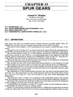
In its
most basic
form
(Fig. 28.1),
a
journal
bearing
consists
of a
rotatable
shaft
(the journal) contained within
a
close-fitting cylindrical sleeve (the bearing). Gener-
ally,
but not
always,
the
bearing
is
fixed
in a
housing.
The
journal
and
bearing sur-
faces
are
separated
by a
film
of
lubricant (liquid
or
gas) that
is
supplied
to the
clearance
space between
the
surfaces.
The
clearance space
is
generally quite small
(on the
order
of
one-thousandth
of the
journal radius)
and has
four
major
functions:
FIGURE
28.1 Journal
and
bearing notation.
CIRCUMFERENTIAL
PRESSURE
DISTRIBUTION
LUBRICANT
SUPPLY
HOLE
.LOAD
LINE
LINE
OF
CENTERS
to
permit assembly
of the
journal
and
bearing,
to
provide space
for the
lubricant,
to
accommodate unavoidable thermal expansions,
and to
tolerate
any
shaft
misalign-
ment
or
deflection.
The
fundamental purpose
of a
journal bearing
is to
provide radial support
to a
rotating
shaft.
Under
load,
the
centers
of the
journal
and the
bearing
are not
coinci-
dent
but are
separated
by a
distance called
the
eccentricity.
This eccentric arrange-
ment establishes
a
converging-wedge
geometry which,
in
conjunction with
the
relative motion
of the
journal
and the
bearing, permits
a
pressure
to be
developed
by
viscous
effects
within
the
thin
film
of
lubricant
and
thus produces
a
load-carrying
capability.
However,
if the
load
is too
large
or the
shaft
rotation
too
slow,
the
wedge-
like
geometry
will
not
form
and
solid-to-solid
contact
can
occur.
Journal bearings
can
operate
in any of
three
lubrication regimes:
thick-film
lubri-
cation,
thin-film
lubrication,
or
boundary lubrication. Generally,
thick-film
operation
is
preferred. Figure 28.2
is a
diagram
of the
three
lubrication regimes. Table
28.1
pro-
vides
some
of the
characteristics
of
each regime.
Journal bearings
may be
classified
according
to the fluid
mechanism that
establishes
the
film
load capacity:
Hydro-
dynamic
journal bearings, also called
self-acting
bearings, depend entirely
on
the
relative motion
of the
journal
and the
bearing
to
produce
film
pressure
for
load
support.
Hydrostatic
journal bearings,
also called
externally
pressurized bear-
ings,
achieve load support
by the
supply
of
fluid
from
an
external high-pressure
source
and
require
no
relative motion
between journal
and
bearing surfaces.
Hybrid
journal bearings
are
designed
to use
both hydrodynamic
and
hydro-
static principles
to
achieve load support
between moving surfaces.
28.2
BEARINGANDJOURNAL
CONFIGURATIONS
28.2.1
Bearing
Geometries
A
wide range
of
bearing configurations
are
available
to the
journal bearing designer.
Figure 28.3 depicts several
of
these
bearings.
The
configurations range
from
the
very
simple plain journal bearing
to the
very complex
tilting-pad
bearing.
The
choice
of
bearing
configuration depends
on
several factors. Among
the
more important
are
cost, load, power loss, dynamic properties, ease
of
construction,
and
difficulty
of
installation.
Journal bearings
are
termed
full
bearings
(Fig.
28.30)
when
the
bearing
surface
completely surrounds
the
journal. Because they
are
easy
to
make
and do not
cost
much,
full
bearings
are the
most commonly used bearing
in
rotating machinery.
Full
bearings become distorted during installation,
and so
they
are
generally
not
per-
fectly
circular.
Journal bearings
are
called partial bearings when
the
bearing surface extends
over
only
a
segment
of the
circumference, generally 180°
or
less (Fig.
28.3Z?).
Par-
SOMMERFELD NUMBER
S
FIGURE 28.2
Three
lubrication regimes:
I,
thick
film;
II,
thin
film;
III, boundary.
COEFFICIENT
OF
FRICTION
f
Lubrication
regime
Thick
film
Thin film
Boundary
Contact
of
bearing surfaces
Only during
startup
or
stopping
Intermittent;
dependent
on
surface
roughness
Surface
to
surface
Range
of film
thickness,
in
1(T
3
-10-
4
ICT
4
to 0.5 X
io-
4
0.5 X
10~
4
to
molecular
thicknesses
Coefficient
of
friction
0.01-0.005
0.005-0.05
0.05- 0.15
Degree
of
wear
None
Mild
Large
Comments
1.
Light-loading
high-speed
regime
2.
Friction
coefficient
proportional
MQVLNI[Wf
(LD)]
1
.
High operating
temperatures
1.
Heavy-loading
(unit load
>
3000
psi) low-
speed
(< 60
fpm)
operating
regime
2.
Heat
generation
and
friction
not
dependent
on
lubricant
viscosity
FIGURE
28.3
Journal bearing
geometries,
(a)
Full bearing;
(b)
partial
bearing;
(c)
elliptical,
or
lemon, bearing;
(d)
offset
bearing;
(e)
rocking jour-
nal
bearing;
(J)
pressure
dam
bearing;
(g)
three-lobe bearing;
(/?)
four-lobe
bearing;
(/)
multileaf bearing;
(/)
floating-ring
bearing;
(k)
tilting-
or
pivoted-
pad
bearing;
(/)
foil
bearing.
TABLE
28.1
Characteristics
of
Lubrication
Regimes
tial
bearings
are
used
in
situations where
the
load
is
mainly unidirectional. Partial
journal bearings have
been
found
to
reduce frictional torque
on the
journal
and
provide convenient accessibility,
and
they
do
not,
in
many instances,
require
strict
manufacturing
tolerance. Partial journal bearings
in
which
the
bearing radius
exceeds
the
journal radius
are
called
clearance
bearings,
whereas partial journal
bearings
in
which
the
bearing
and the
journal radii
are
equal
are
termed
fitted
bearings.
Geometries
in
which
two
circular sectors
are
employed
are
called
elliptical,
or
lemon,
bearings
(Fig.
28.3c).
These bearings
are
really
not
elliptical
at all but are
fab-
ricated
by
uniting
two
halves
of a
circular bearing which have
had
their mating
faces
machined
so
that
the
bearing
has an
approximately elliptical appearance. Lemon
bearings
are
probably
the
most widely used bearing
at low and
moderate
speeds.
They
are
extensively used
in
turbine applications.
Elliptical bearings
in
which
the two
cylindrical halves
are
laterally displaced
along
the
major
axis
are
termed
offset
bearings
(Fig.
28.3J).
The
relative displace-
ment
of the
center
of
each
half
of the
bearing
is
called
the
preset. When
the
upper
half
of the
bearing
is
displaced horizontally
in the
direction
of
rotation,
the
bearing
has
negative preset.
It is
found
that load capacity increases with preset.
Offset
bear-
ings
have relatively high horizontal
stiffness,
which helps prevent dynamic instabil-
ity.
Further,
offset
bearings allow greater lubricant
flow and so run
cooler.
Novel
offset
journal bearing designs
for
reducing power loss
and
wear
in
duty
cycles
which combine
nonreversing
loading with limited journal angular oscillation
or in
steady operation with counterrotation
of
journal
and
bearing under
a
constant
load have been studied.
In
these applications, conventional journal bearings
are
found
to
develop extremely thin lubricant
films,
which
in
turn results
in
high friction
and
wear. Figure
28.3e
depicts
a
journal bearing
in
which both
the
journal
and the
bearing
are
divided axially into segments with
offset
centerlines. This arrangement
produces
a
dynamic rocking motion which promotes
a
thicker lubricating
film.
Accordingly
the
assembly
has
been
called
a
rocking journal
bearing.
When
a
step
is
milled
from
the
surface
of the
bearing (Fig.
28.3/),
the
resulting
bearing
is
called
a
pressure dam,
or
step,
bearing.
The
purpose
of the
step
is to
create
additional hydrodynamic pressure
on the top of the
journal
as the
lubricant
is
rotated into
the
step.
In
turn, this pressure buildup enhances
the
load
on the
journal
and
therefore diminishes
its
susceptibility
to
vibration problems. Pressure
dam
bear-
ings
are
very popular
in the
petrochemical industry.
Bearing geometries consisting
of
three
or
more sectors (Fig.
28.3g
and ti) are
termed
lobed,
or
multilobed,
bearings.
Generally, bearings with more than three
lobes
are
used only
in gas
bearing applications. Multilobe bearings
act as a
number
of
partial bearings
in
series.
The
cost
of
multilobed bearings
is
considered moderate.
The
multileaf
journal
bearing
(Fig.
28.3/)
is a
variant
of a
multilobe bearing.
It
consists
of a
number
of
identical circular arcs,
or
leaves, whose centers
are
equally
spaced around
the
generating circle.
The
operating characteristics
of a
multileaf
bearing
are
practically independent
of the
direction
of
loading
for
bearings with
eight
or
more leaves.
In
&
floating-ring
journal
bearing
(Fig.
28.3/),
the
lubricating
film
is
divided
in two
by
the
addition
of a
"floating" ring between
the
journal
and the
bearing. Floating-
ring
bearings have lower
frictional
losses
and
reduced heat generation
and
provide
better stability.
Hydrodynamic journal bearings
may be
distinguished
as to
whether
the
bearing
surface
can
pivot.
The
basic advantage
of
pivoting,
or
tilting-pad,
journal
bearings
(Fig.
28.3A:)
over
fixed-pad
journal bearings
is
that they
can
accommodate, with little
loss
in
performance,
any
shaft
deflection
or
misalignment.
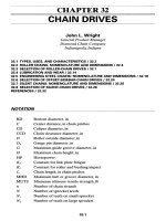
FIGURE 28.4
Journal
shapes,
(a)
Hourglass;
(ft)
barrel;
(c)
tapered;
(d)
herring-
bone;
(e)
partly grooved symmetrical
pattern:
(/)
partly grooved asymmetrical pat-
tern.
(Parts
(d),
(e),
and
(f)
are from
[28.1].)
28.3
BEARINGMATERIALSANDSELECTION
CRITERIA
28.3.1
Bearing
Materials
The
ideal journal bearing material would have
the
following
characteristics:
1.
High compressive strength
to
withstand
the
applied radial loading
2.
High
fatigue
strength
to
endure
any
cyclic changes
in
load direction and/or load
intensity
3.
Compatibility with
the
journal material
to
minimize surface scoring
and
bearing
seizure whenever
the
journal
and
bearing surfaces come into contact (e.g., during
startup)
4.
Embedability
to
permit foreign particles
in the
lubricant
to
penetrate
the
bearing
surface
to
avoid scoring
and
wear
A
foil
journal bearing (Fig.
28.3/)
consists
of a
very thin compliant bearing surface
resting atop
a
series
of
corrugations. When
it is
compared
to a
conventional
gas
bear-
ing,
the
foil
bearing
has a
thicker
film,
higher load capacity, lower power loss, better
stability,
and
superior endurance
to
high operating temperatures.
28.2.2
Journal
Shapes
Although
the
journal
is
generally assumed
to be
perfectly circular, wear
effects
or
poor
manufacture
can
lead
to
journals with
the
shapes shown
in
Fig.
28.40,
b, and c.
In
addition,
the
possibility
of
developing pressure
by
grooving
the
surface
of the
journal
has
been investigated.
Three
grooved patterns that were
found
to
yield good
stability characteristics
are
shown
in
Fig.
28.4c,
d,
and e.
5.
Conformability
of
surface
to
tolerate journal misalignment, deflection,
or
manu-
facturing
inaccuracies
6.
High corrosion resistance
to
withstand chemical attack
by the
lubricant
7.
High thermal conductivity
to
permit generated heat
to be
transported
from
the
lubricant
film
8.
Appropriate
coefficient
of
thermal expansion
to
avoid
differences
in
thermal
expansion
of the
journal
and
bearing
9. Low
wear
to
prevent
surface
destruction, especially under boundary lubrication
conditions (i.e.,
thin-film
high-friction
lubrication)
and
thereby lengthen
the
life
of
the
bearing
Besides
all
these,
the
material should
be
inexpensive,
highly
available,
and
easily
machined.
To
be
sure,
no
single material
has
been developed that
satisfactorily
combines
all
characteristics
of the
ideal bearing material.
In
fact,
some
of the
characteristics
are
contradictory.
For
example,
soft
bearing materials generally
do not
have
sufficient
strength.
To
strengthen
soft
bearing materials, they
are
frequently
bonded
to
stronger backing materials. Bearing linings
or
overlays
may be
cast, electrode-
posited, sprayed,
or
chemically applied,
and
they have thicknesses
which
range
from
0.01
to 0.5
inch (in).
Journal bearing materials
may be
broadly divided into
two
groups: metallics
and
nonmetallics.
The
metallic group includes aluminum alloys, babbitts
(tin-,
lead-,
and
aluminum-based),
copper alloys (brass
and
bronze), zinc,
and
iron.
The
nonmetallic
group includes plastics, carbon graphites, cemented carbides,
and
other proprietary
materials.
The
nonmetallics have been widely used
in
self-lubrication applications
because they
can
provide
low
friction
and
wear without
the aid of a
lubricant.
Because
of the
wide diversity
of
materials available
for use in
journal bearings,
it
is
difficult
to
provide comprehensive tables
of all
relevant properties.
Manufacturers
and
materials suppliers
are the
best sources
for
that information. Nevertheless, some
physical
properties
of a
variety
of
journal bearing materials
are
presented
in
Table
28.2
[28.2].
Typical applications
and
useful
comments concerning
a
number
of
jour-
nal
bearing alloys
are
displayed
in
Table 28.3, while Table 28.4 contains
a
numerical
ranking
of the
performance characteristics
of
these alloys.
General information
for a
variety
of
self-lubricating
materials
is
given
in
Table
28.5
[28.3].
Note that
the
table contains maximum values
of the PV
factor. This fac-
tor is the
product
of the
bearing load
per
unit
of
projected area
and the
sliding veloc-
ity
(i.e., speed
in
revolutions
per
minute times
the
bearing circumference).
The PV
parameter provides
an
indication
of
material wear
and
internal heat generation.
Failure
in
self-lubricated bearings
is
frequently
the
direct result
of
internal over-
heating.
28.3.2
Bearing
Material Selection
Criteria
Selection
of a
bearing material invariably requires
a
compromise based
on
particu-
lar
characteristics regarded
by the
designer
to be of
principal importance
to the
application
at
hand.
DeGee
[28.4]
has
developed
a
systematic approach
for
selecting
a
material
for
lubricated journal bearings.
In
this method, certain component crite-
ria are
identified
within
major
property groups. Table 28.6 gives
one
such listing.
Not
all the
criteria presented
in
Table 28.6 need
be
considered.
For
example,
in a
particular
application, environmental properties
may be of no
concern because
the
Density,
lbm/ft
3
630
462
562
655
537
181
555
549
487
449
399
381
144
137
71
85
89
75
89
75
42
106
886
243
Coefficient
of
expansion,
Min/(in-°F)
14
13
11
10.9
16.6
13.5
9.9
10
6.4
5.7
10.5
6.7
55
55
12
45
70
22
43
2.7
1.5
3.3
8.2
Thermal
conductivity,
Btu/(h-ft-°F)
14
32
170
238
53
119
27
29
29
30
17
16
0.10
0.14
0.21
0.13
0,11
0.44
0.09
0.11
10
40
1.6
Modulus
of
elasticity,
Mpsi
4.2
7.6
7.6
11
8
10.3
14
16
30
23
0.06
0.41
0.5
0.41
0.32
'l'.8
2
81
50
Tensile
strength,
kpsi
10
11
8
23
"22
34
45
75
35
18
25
15
3
11
10
10
8.5
7.5
1.1
2
130
30
Hardness
HB
21
25
25
25
35
45
60
70
150
180
40
50
H55t
D60J
M79t
MlOO
M94
M70
E99t
"75§
A91|
A85
Material
Metals
Lead
babbitt
Tin
babbitt
Copper
lead
Silver
Cadmium
Aluminum
alloy
Lead bronze
Tin
bronze
Steel
Cast iron
Porous metals
Bronze
Iron
Aluminum
Plastics
TFE
Nylon
Phenolic
Acetal
Polycarbonate
Filled polyimide
Other nonmetallics
Rubber
Wood
Carbon graphite
Cemented tungsten carbide
Fused
aluminum oxide
TABLE
28.2 Physical Properties
of
Journal Bearing Materials
fRockwell.
!Shore
durometer.
§Shore
scleroscope.
SOURCE:
Ref.
[28.2],
bearing
operates
in a
clean,
moderate-temperature
environment
and is not
part
of
an
electric
machine.
After
the
list
of
criteria
has
been
established,
each
component
criterion
is
com-
pared
with
all
other
criteria,
and a
graduation
mark
is
allocated
from
O,
if
there
is no
difference
in the
criterion,
to 3, if
there
are
large
differences.
For
example,
compres-
sive
strength
(Al in
Table
28.6)
might
receive
a O
when
compared
with
fatigue
strength
(A2)
but
receive
a 3
when
compared
to
thermal
conductivity
(Bl),
and so
forth.
When
all
component
criteria
have
been
compared
with
one
another
and
grad-
uation
marks
assigned,
the
graduation
marks
of
each
criterion
are
totaled
and the
sum
of all
these
totals
is
divided
into
each
amount,
to
obtain
the
component
criteria
weighting
factors.
The sum of all the
weighting
factors
obviously
is
unity.
TABLE
28.3 Bearing Alloy Material Applications
Material
Aluminum,
low
tin
Aluminum,
high
tin
Babbitt, tin-based
Babbitt,
lead-
based
Lead
bronze
Phosphor bronze
Copper lead (cast)
Copper lead
(sintered)
Silver (oven-
plated)
Nominal
composition,
%
by
weight
Al
92
Sn
8
Al
80
Sn
20
Sn
84
Cu
8
Sb
8
Pb 75
Sn 10
Sb 15
CuTO
Pb 25
Sn
5
Cu
80
Sn 10
Pb 10
Cu 75
Pb 25
Cu 75
Pb 25
Applications
and
remarks
Tin
added
to
improve compatibility;
too
much
tin
lowers strength.
Has
thermal expansion
problems
in
steel housings. Requires hard
journals. Good
at
high temperatures. Used
in
diesel engines
and
compressors.
Produced
by
special working
and
annealing
process
so tin
content does
not
greatly reduce
strength.
Used
in
automotive engines
(crankshafts)
and in
aircraft
equipment.
Fatigue strength decreases
as
thickness increases.
Low
load capacity, thus usually bonded
to one
(bimetal)
or two
(trimetal)
backing materials.
Good
in
dirty applications,
motors.
Antimony
(Sb) greater than
15%
can
cause
brittleness.
Cheaper than tin-based
babbitt.
Used
in
crankshaft bearings, transmission
bushings,
and
electric equipment.
Good
for
high-load high-speed applications;
can
be
used with
soft
journals. Used
as
bushings
in
pumps,
many home appliances, railroad cars.
General-duty popular bushing;
tin
added
to
improve strength.
Has
high hardness; should
be
used
with harder journals (300 BHN).
Good
impact resistance; used
in
lathes, pumps, home
appliances.
Lead
in
pockets
in
copper matrix. Lead improves
bearing surface
but has
corrosion problems.
Frequently used
as
lining
material
on
steel-
backed bearings. Used
in
heavy-duty
applications.
Frequently
used with
a
babbitt overlay
in a
trimetal
bearing.
Widely used
in
heavy-duty
(high-temperature high-load) applications.
Frequently used with lead indium overlay.
Fatigue
Corrosion
Seizure Thermal
strength resistance resistance
Embedability
Compatibility conductivity
Nominal
composition,
%
by
weight
Material
2421
1 4
2422
2 4
1545
4 3
1345
4 2
4233
2 3
4231
2 3
3133
3 4
3133
3 4
5411
1 5
Al
92
Sn
8
Al
80
Sn
20
Sn
84
Cu
8
Sb
8
Pb 75
Sn 10
Sb 15
Cu 70
Pb 25
Sn
5
CuSO
Sn 10
Pb 10
Cu 75
Pb 25
Cu
60
Pb 40
Aluminum,
low tin
Aluminum,
high
tin
Babbitt, tin-based
Babbitt, lead-based
Lead bronze
Phosphor bronze
Copper
lead (cast)
Copper
lead
(sintered)
Silver (over-plated)
TABLE
28.4 Performance Ratings
from
5
(High)
to 1
(Low)
for
Bearing Alloy Materials
Resistance
to
chemical
§
Good
Good
Good
Good
Good
Good
Good
Good
Excellent
Excellent
Resistance
to
humidity
Fair
Good
Good
Good
Fair
Good
Good
Good
Excellent
Excellent
Critical
temperature,
0
F
400
300
600
300-400
400
300
600
300-400
500
Friction
coefficient
0.1-0.4
0.1-0.4
0.1-0.3
0.9-1.1
0.1-0.4
0.05-0.15
0.1-0.3
0.1-0.4
0.05-0.25
0.05-0.25
Maximum
PV
factor,
\
kpsi-fpm
1
1
0.3
0.1
1
2.5
6
4
5-20
1-10
Maximum
speed,
fpm
200-400
200-500
1000
1000
200-400
800
1000
200
500-1000
50
Maximum
load,t
kpsi
1.5
1.5
10
4
2
1.8
10
4-5
1
100
Material
Nylon
Acetal
Polyimide
Phenolic
Filled nylon
Acetal
PTFE
filled
Filled polyimide
Reinforced phenolic
Filled
PTFE
PTFE
fLoad
on
projected
area
at
zero
speed.
|For
continuous
service.
§At
bearing
surface.
SOURCE
Ref.
[28.3].
TABLE
28.5
General
Information
on
Self-Lubricating Bearing Materials
Next
the
candidate materials
are
given quality marks
for the
various component
criteria. These marks range
from
5
(excellent,
or
high)
to 1
(poor,
or
low).
For
instance, tin-based babbitts
are
known
to
have only
fair
(2)
fatigue
strength, whereas
they
have excellent
(5)
resistance
to
corrosion.
The
final
ranking
of the
candidate
materials
is
obtained
by
comparing
the
sums
of the
products
of all
component crite-
ria
weighting
factors
and
quality marks.
28A
PRESSUREEQUATION
FOR
A
LUBRICATING FILM
28.4.1
Reynolds
Equation
The
differential
equation which governs
the
pressure
in a
lubricating
film
is
called
the
Reynolds equation. Bearing performance
can be
evaluated once
the
solution
of
this
equation
is in
hand.
To
develop
the
Reynolds equation, consider
a
portion
of the fluid
film
of a
jour-
nal
bearing (Fig.
28.1).
In
general, there
are
three velocity components
in the
film:
u,
v,
and
w.
There
are
three equations
of
motion (momentum equations),
one for
each
coordinate direction.
The
collection
is
known
as the
Navier-Stokes
equations,
and
each equation
may be
written
in the
following
form:
Inertial forces
=
pressure forces
+
body forces
+
viscous forces (28.1)
The
Navier-Stokes equations
in
their complete
form
are too
involved
for
analytical
solution. They can, however,
be
reduced,
and
subsequently solved,
by
making several
simplifying
yet
plausible assumptions:
TABLE
28.6 Journal Bearing Material Selection Criteria
Major
property group
A.
Mechanical
B.
Thermal
C.
Chemical
D.
Manufacturing
E.
Environmental
F.
Tribological
Component criteria
1
.
Compressive strength
2.
Fatigue strength
3.
Conformability
(modulus
of
elasticity)
1.
Thermal conductivity
2.
Thermal expansion
1.
Corrosion rate
1.
Cost
2.
Machinability
3.
Availability
of
material
1.
Behavior under abrasive conditions (embedability)
2.
Resistance against electric-discharge pitting
3.
Resistance
to
thermal degradation
1.
Wear rate
2.
Coefficient
of
friction
3.
Cavitation
erosion resistance
1. The flow is
laminar.
2. The
inertial
and
body forces
are
small compared
to the
pressure
and
viscous
forces.
3. The
curvature
of the
film
is
negligible;
the
bearing surfaces are, therefore, nearly
parallel.
4. The
variation
of
pressure across
the
film
BPIBy
is
negligibly small.
5. The
transverse velocity component across
the
film,
v, is
small compared
to the
other velocity components.
6. The
velocity gradients across
the
film
dominate over
all
other
velocity gradients.
Application
of
these assumptions
to
mathematical versions
of Eq.
(28.1),
and to
an
integrated version
of the
conservation
of
mass
(the
continuity
equation),
yields
the
Reynolds equation
for a
liquid-lubricated bearing:
a/*|A
+
f(^)
=
6(Ub
+
Ui
^JL
+6h
^^
+
l2
f
(28
.
2)
Bx
\
[I
Bx)
Bz \
Jl
Bz
/
Bx Bx Bt
The
first
grouping
on the
right-hand side
of Eq.
(28.2)
is
called
the
wedge
term
and
must
be
negative
to
generate positive pressures.
The
third term
on the
right
is
called
the
squeeze term,
and it
will
generate positive
pressures
when
Bh/Bt
<
O.
The
squeeze term vanishes
for a
steadily loaded bearing. Both
the
wedge
and the
squeeze terms vanish
for a
purely hydrostatic case.
If the
bearing surface
is
fixed
(Ub
= O), if the
shaft
is
rotating with
a
speed
co
(that
is,
Uj=
U =
,RCG),
and if the
vis-
cosity
of the
lubricant
is
constant, then
Eq.
(28.2)
may be
written
as
9
f,*3p\
3
(,*dp\
,
dh
,
,
BU
Bh ,
^
—
(h
3
^-
+—
/z
3
^
U6jiflco
—
+
6u/i
—
+
12|i—
(28.3)
dx
\
BxJ
Bz
\
Bz]
Bx
^
Bx
^Bt
^
'
For
comparative purposes,
it is
useful
to
cast
the
steady version
of Eq.
(28.3)
into
nondimensional
form.
This
can be
accomplished
by
defining
the
following nondi-
mensional
variables:
ft-
X
r-
Z
H-
h
Q
=
~R
C=
L/2
H
=
~C
- P
(cv_
P
/cy
P
6[Ji(U/R)[R)
6[La[R)
Also, since
co =
2nN,
-_
P /CY
p
UK[IN[R)
Substituting
these into
Eq.
(28.3) yields
^("-D^fJ^^D-f
This
equation
can be
interpreted
as
Circumferential
pressure
flow
+
axial pressure
flow
=
shear
flow
The
governing equation
of a gas
film
differs
from
that
of a
liquid
film
by the
appearance
of the
density
p. The
steady compressible version
of the
Reynolds equa-
tion
for an
isoviscous
gas can be
written
ftaf)4taf)
=
6^^
(28
.
5)
dx
\
dx
]
dz
\
dz)
ox
Since
the
energy dissipated
by
frictional forces
is
very small
in
normal
gas
bear-
ing
operation,
we may
assume that
the
film
has a
constant temperature
and p = Ap;
thus,
Eq.
(28.5) becomes
3(^)
3(
tf
«
=
12Mto
3&*!
(28
.
6)
ox
\
3:c
/
oz
\
oz
J
ox
This
equation
can be
written
in
nondimensional
form
as
a
/
ap>\
/Dy
a
/
3?\
^H)
aer
~M)
(T)
acr
ICT
^e"
(28J)
where
p
=
—
p
a
=
ambient
or
supply pressure
Pa
h
z
6uW*V
H
=
~c
^-
La
A
~
Pa
(c)
Here
A is
called
the
bearing,
or
compressibility,
number.
To
solve
the
Reynolds equation,
we
require
an
expression
for the
film thickness
h.
From
the
triangle
ABC in
Fig. 28.4,
we may
write
AC = h + R =
R
b
cos
%
+ e cos 9
where
6 is
measured
from
the
line
of
centers.
And
since
e
«
R
b
,
cos
^
~ 1, and
thus
h
=
R
b
- R + e cos
9
The
radial
clearance
is C
=
R
b
- R, and the
eccentricity
ratio
is e
=
elC;
hence
h =
C(I
+ecos
9)
(28.8)
28.4.2
Boundary Conditions
Three sets
of
circumferential boundary conditions
are
commonly applied
to the
solutions
of the
Reynolds equation. These boundary conditions have been given
the
names Sommerfeld,
Gumbel,
and
Swift-Stieber.
Of the
three,
the
Sommerfeld condi-
tions
are the
easiest
to
apply,
but
they yield certain unrealistic results.
For
example,
in
a
liquid-lubricated bearing, Sommerfeld conditions produce negative pressures
in
the
film.
This results
in the
shaft's being displaced
at
right angles
to the
load line
as
the
load
is
increased. Gumbel conditions
are
similar
to
Sommerfeld conditions
except that
all
negative pressures
are
disregarded. Although this approach leads
to
more realistic load results,
it
produces
a
violation
of the
conservation
of
mass.
The
Swift-Stieber
conditions come closest
to
representing
the
actual conditions
in a
film,
but
they
are
more
difficult
to
apply. They
are
widely used
in
numerical investiga-
tions.
The
three
sets
of
boundary conditions
are
summarized
in
Table 28.7.
28.5
JOURNALBEARINGPERFORMANCE
Once
the
pressure
distribution
is
established,
the
journal bearing performance
may
be
determined. Performance
is
generally measured
in
terms
of
four
quantities: bear-
ing
load capacity,
frictional
losses, lubricant
flow
requirement,
and
temperature rise.
28.5.1
Bearing
Load
Relations
Five parameters
are
associated with
the
load capacity
of a
journal bearing:
1. The
radial load component
W
R
acts along
the
line
of
centers (Fig. 28.1)
and is
computed
from
fa
,63
WR
=-R
\
p cos
6
d0
dz
J
-L/2
J
Qi
TABLE
28.7 Typical
Boundary
Conditions
on the
Reynolds
Equation
Names
associated
with
boundary conditions
Sommerfeld
(full
Sommerfeld)
Gumbel (half
Sommerfeld)
Swift-Stieber
(Reynolds)
Pressure
profile
Mathematical expression
P(O
1
)
=
P(S
3
)
=
O
(zero
pressure
means ambient
or
atmospheric
pressure)
For
complete journal bearings:
O
1
=
O,
O
3
=
27T
For
partial journal bearings:
O
1
=
P
1
,
O
3
=
O
1
+
0
№i)
=
P(O
2
)
=
O
P(O
2
<
O
<
O
3
)
= O
For
complete journal bearings:
O
1
=
O,
O
2
=
TT,
O
3
=
2w
P(O
2
)
—
/?
cav
=
atmospheric pressure
s«-«
#2
=
#cav
which must
be
determined
where
61 and
6
3
are, respectively,
the
leading
and
trailing angular locations
of the
lubricating
film.
2. The
tangential load component
W
T
acts perpendicular
to the
line
of
centers:
WT
=
R
\
\"
P
sine
dQdz
J
-L/2
J
Qi
3. The
bearing load
W
must
be
supported
by the
pressure developed within
the
lubricating
film.
Generally
the
load
is
specified
or
enters
the
design
via the
unit
load
P,
which
is
defined
as the
load
per
unit projected area,
or
P
=
^
LD
Typical
values
of the
unit load
are
given
in
Table 28.8.
TABLE
28.8
Range
of
Unit
Loads
for
Various
Applications
Application
Bearing
Unit load
range,
kpsi
Automotive
engines
Main
0.6-0.8
Crankpin
1.7-2.3
Diesel
engines
Main
0.9-2.3
Crankpin
1.1-2.3
Wristpin
2.0-2.3
Steam
turbines
Main
0.12-0.25
Air
compressors
Main
0.14-0.28
Crankpin
0.28-0.5
Centrifugal
pumps
Shaft
0.1
-0.18
Electric
motors
Shaft
0.12-0.25
4. The
Sommerfeld
number
S is a
dimensionless parameter that characterizes bear-
ing
performance; large
S
(say, greater than 0.15) indicates
a
lightly loaded bearing
operating
at a
small eccentricity.
The
Sommerfeld number
may be
calculated
from
ViUL(RV
yN(R\
2
A
"
nW
(c)
~
P (c)
5. The
attitude angle
ty is the
angular distance between
the
load line
and the
line
of
centers (Fig. 28.1).
It
locates
the
minimum
film
thickness
as
measured
from
the
load line. Because
W
R
= W cos ty and
W
T
= W sin
(J),
* <£
28.5.2
Bearing
Friction Relations
Four parameters
are
involved with
the
frictional behavior
of a
journal bearing:
1. The
shear
stress
T,
acting
on
either
the
shaft
or the
bearing
surface,
consists
of two
terms;
one is due to
motion
of the
shaft
(pure shear),
and the
other
is due to the
circumferential
pressure distribution (pressure-induced shear):
[IU
+
h dp
T
"
h
±
2R
ae
The
plus sign corresponds
to the
shear stress
on the
journal surface;
the
minus
sign,
to the
shear stress
on the
bearing surface.
2.
The
frictional
force
acting
on the
journal
F
7
is
found
by
integrating
the
pure shear
stress over
the
entire surface
of the
journal
and the
pressure-induced shear stress
up to the
trailing edge
of the
film.
This yields
/
2n
\,
JR\
zW
T
(C\
F
>
=
(T3F)<^>(c)
+
—
(R)
3. The friction
coefficient
f
is the
ratio
of the
journal frictional force
to the
bearing
load:
f=^
J
W
The
friction
variable
is the
product
(RIC)(f)
and so may be
written
0-(1^K
1
T
4
4. The
power that must
be
supplied
to the
journal
to
overcome friction
is
called
the
frictional
horsepower
loss
HP, and it may be
computed
from
HP-
C
1
FjU
=C
2
f'WRN
where
Ci
and
C
2
depend
on the
system
of
units.
For
F
7
in
pounds
(Ib)
and U in
inches
per
second (in/s),
C
1
=
1
Am
for W
(Ib),
R
(in),
and
TV
in
revolutions
per
sec-
ond
(r/s),
C
2
-
2TcC
1
-
9.51998
x
10'
4
.
The
relevant geometry
for the
execution
of
these tasks
is
depicted
in
Fig. 28.5.
28.5.3
Lubricant Flow Relations
Lubricant
flow
rates
are
needed
to
estimate
the
capacity
of the
lubricant supply
system
and to
determine
the
cooling requirements
of the
bearing. This involves
evaluation
of the
lubricant
flow
within
the
clearance space,
the
lubricant
flow
that
leaks
out the
sides
of the
bearing,
and the
lubricant
flow
that
is
supplied
to the
bearing.
In
general, volume
flow
rate
per
unit
length
is
composed
of a
term
due to
sur-
face
motion (shear
flow) and
another
due
to the
pressure (pressure-induced
flow).
Journal bearing circumferential
and
axial
flows per
unit length
are
uh _
h
3
a/?
h
3
a/?
q
*~
2
~12u7?
ae
^~~12jLi
Bz
(28.9)
The
total
flow
rates
may be
found
by
integrating
Eq.
(28.9) across
the
bearing
length
for the
circumferential
flow
rate
FIGURE
28.5
Film
thickness
geometry
and
around
the
bearing circumference
for
the
axial
flow
rate.
Assuming
that lubricant
is
supplied
in
the
unloaded portion
of the
bearing (Fig. 28.6),
we see
that
the
rate
at
which lubri-
cant
leaks
out of the
active portion
of the
film
is
a«
=
Qi-Q
2
(28.10)
where
Qi
= flow
into
the
leading edge
of
the
film
and
Q
2
= flow out of the
trailing
edge.
When
the
input
flow
rate equals
the
leakage
flow
rate,
Qi
is
called
the
classi-
cal
rate.
For
given values
of W,
U,
and
(i,
the
classical rate
is the
largest
flow
that
can be
carried into
the
active
film
by
shaft
rotation. However,
in
practice,
Q^
the
input
flow
rate,
may be
greater (the
flooded
condition)
or
less (the
starved
condition)
than
the
appropriate value
to
achieve
the
classical rate.
For flooded
conditions, side
flow
will
also occur
in
the
unloaded portion
of the
bearing,
and
we
may
write
FIGURE 28.6
Control
volumes
for
lubricant
Q
—
Q+Q._Q
flow
and
heat
balances.
su
2
l
l
(2811)
thus,
Q
su
+Q
sa
=
Q
s
=
Qi
28.5.4
Bearing
Thermal
Relations
The
steady energy balance equation
can be
simply expressed
as
Energy
inflow
rate
-
energy outflow rate
+
energy generation rate
=
O
An
energy balance
may be
performed
on the
unloaded portion
of the
film
(Fig.
28.6). Toward that end,
it is
assumed that there
is
complete mixing between
the
inlet
Qi
and the
carryover
Q
2
flows
so
that
T
u
=
7\.
It is
further
assumed that there
is no
energy generation
and
negligible heat transfer.
Hence,
for the
unloaded portion
of
the
film,
QiTt
+
Q
2
^T
2
=
(Q
2
+
Q
1
)(T
1
)
(28.12)
Next
an
energy balance
is
performed
on the
active portion
of the
lubricating
film
(Fig.
28.6).
The
energy generation
rate
is
taken
to be
Fj
UIJ,
and the
conduction heat
loss
to the
shaft
and
bearing
are
taken
to be a
portion
of the
heat
generation
rate,
or
XFj
UIJ.
Accordingly,
PGiCT
1
-
(?Q
sa
C*T
a
+
PQ
2
CT
2
)
+ fl"^*
7
=
O
(28.13)
Combining
Eqs.
(28.10)
to
(28.13)
and
assuming that
the
side-flow
leakage occurs
at
the
average
film
temperature
T
0
=
(Ti+
2
T
2
)/2,
we
find
that
JpC*(T
a
-
T
1
)
_
1
+
2Q
2
IQ
1
4n(RIC)<f)
(1-X)P
2-QJQi
QiI(RCNL)
*•
'
'
This shows that
the
lubricant temperature
rise
is 1 -
X
times
the
rise when conduc-
tion
is
neglected.
28.6 LIQUID-LUBRICATED JOURNAL BEARINGS
In the
hydrodynamic operation
of a
liquid-lubricated journal bearing,
it is
generally
assumed that
the
lubricant behaves
as a
continuous incompressible
fluid.
However,
unless
the
lubricant
is
admitted
to the
bearing under relatively high hydrostatic
head,
the
liquid
film
can
experience periodic vaporization which
can
cause
the
film
to
rupture
and
form
unstable pockets,
or
cavities, within
the
film.
This disruption
of
the
film
is
called
cavitation,
and it
occurs when
the
pressure within
the
bearing
falls
to the
vapor pressure
of the
lubricant. Narrow liquid-lubricated bearings
are
espe-
cially
susceptible
to
this problem. Figure
28.7
illustrates
the
general
film
condition
in
which
lubricant
is
admitted through
a
lubricating groove
at
some angular position
G
0
.
Clearly
incomplete
films
complicate
the
analysis,
and
therefore
the
design,
of a
liquid-lubricated
journal bearing.
28.6.1
LID
Effects
on
Cylindrical Full Journal
Bearings
Long-Length
Bearings. When
the
length
of a
bearing
is
such that
L >
2D,
the
axial
pressure
flow
term
in the
Reynolds equation
may be
neglected
and the
bearing
per-
forms
as if it
were
infinitely
long. Under this condition,
the
reduced Reynolds equa-
tion
can be
directly integrated. Table
28.9
contains long-bearing results
for
both
Sommerfeld
and
Gumbel boundary conditions.
Short-Length Bearings. When
the
length
of a
bearing
is
such that
L <
D/4,
the
axial
pressure
flow
will
dominate over
the
circumferential
flow, and
again
the
Reynolds equation
can be
readily integrated. Results
of
such
a
short-bearing inte-
gration
with Gumbel boundary conditions
are
shown
in
Table
28.10.