Tài liệu The Plastic Product P1 docx
Bạn đang xem bản rút gọn của tài liệu. Xem và tải ngay bản đầy đủ của tài liệu tại đây (1.25 MB, 10 trang )
11
2 The Plastic Product
Plastics have evolved to be a very useful material. Today, plastics are used in
almost every area, from small bottle caps, disposable cutlery, and packages
for dairy products, to large containers, such as laundry baskets and garbage
pails.
Plastics have transitioned from a “cheap” substitute for metal and glass to
the material of choice providing almost unlimited design freedom, unique
properties, and significant cost savings.
Figure 2.1 shows various industrial containers and house wares that create
durable products in cycles from 10–30 seconds.
Figure 2.2 shows various thin-walled containers are typically used in the dairy
industry and are molded with wall sections typically less than 0.7 mm with
cycles of 20 shots per minute.
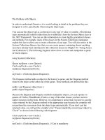
Figure 2.3 shows a collection of PET bottles for water, soft drinks, etc. and
some of the preforms used for blowing these bottles. Today, more than 500,000
tonnes annually of plastic are converted into bottles. Cycle times for molding
these parts have been reduced from 35 to 8 s in the last 20 years. In addition,
cavitations have increased from 8 to 144 cavities, resulting in significantly
lower product costs.
Figure 2.4 shows a sampling of “stadium cups” with printed or in-mold
labelled decorations.
Figure 2.6 shows samples of small, thin-walled technical products made from
engineering plastics such as ABS, Acrylic, and PC.
Figure 2.1 Molded products of various sizes
(Courtesy: Husky)
Figure 2.2 Various thin-walled containers
(Courtesy: Husky)
Figure 2.3 PET bottles for water, soft drinks,
etc. and some of their preforms
(Courtesy: Husky)
Figure 2.4 Stadium cups
Figure 2.5 Small and large technical (engineering) products, heavy-walled jars
for cosmetics, and tubular containers with integral, hinged lids (Courtesy: Husky)
1281han02.pmd 28.11.2005, 10:4811
12
2 The Plastic Product
2.1 The Product Design
The following contains suggestions for the product design and how it may
impact the mold design and the productivity of the mold
A new mold is usually required
For a new product
After the redesign of an existing product
To increase the productivity and the output of the production facilities
already in place. This usually provides a good opportunity to reevaluate
and improve the product, and to reduce manufacturing costs, particu-
larly through the reduction of the plastic mass of the product.
The mass of the plastic accounts for a significant portion of the cost of every
product. Reducing wall thickness and reduction of unnecessarily heavy cross
sections will not only reduce the cost of plastic material for the product, but
will also result in – sometimes significantly – faster molding cycles. The result
is that more of the products can be made per hour at lower cost than was
possible with the preceding design.
In such a case, important considerations are
The output of the plasticizing unit and the dry cycle of the machine
manufacturing the product before the planned changes
If there was special handling equipment (product removal, stacking,
printing, etc.) with the old mold, will it be able to handle the greater
output, or will it need improvements as well
The above will be discussed in more detail later in this book.
Figure 2.6 Small, thin-walled technical
products made from engineering plastics
1281han02.pmd 28.11.2005, 10:4812
13
2.2 Product Drawings
2.2 Product Drawings
Occasionally, only samples or CAD models of a new product are available.
This may be of some advantage to better visualize the product, but it is
absolutely necessary, to minimize risk for all parties involved in the final
decision, to have a complete detail drawing of the product, showing all
features, tolerances, and specifications.
This is also the moment when the designer has the greatest opportunity to
decide on the most suitable design for the mold, and/or to make suggestions
on how the product design might be modified to improve the productivity,
to simplify the mold design, and to reduce mold costs. This is also the time
to consider any ancillary equipment required for this production. An
opportunity graph (Fig. 2.7) shows symbolically the value of planning a
project. At the outset of the project, the opportunity to make improvements,
revisions, and selections is highest to affect the final outcome of the project,
while the costs are lowest. After concept analysis, once the elements of the
project have been agreed upon and as engineering of the mold progresses,
the opportunity to make conceptual changes or improvements diminishes,
and any costs associated with it will increase. By the time the project reaches
completion and gets into testing and production, the opportunity to make
changes is low, and any costs could be very high.
To confirm that the part drawing is acceptable to all parties it should always
be signed off in writing as acceptable. Appendix 12 provides some general
advice for the designer on how to critique a part drawing.
2.2.1 Product Shape:
How Can the Product Best Be Molded?
Here, even an experienced, conscientious designer may want to consult with
another (knowledgeable) colleague, and/or with anyone else who is familiar
with the type of product for which the mold is to be built, and discuss
problems of making and of operating such a mold, to get their input regarding
the proposed product design. In the following, some of the most important
areas to be contemplated are discussed.
2.2.2 Parting Line (P/L)
Is There an Obvious Location for the (Main) Parting Line?
In many products, the location of the parting plane (parting line, P/L) is
obvious. It is along the largest cross-sectional dimension of the product, at
right angles to the motion of the opening and closing of the mold, and should
preferably be in one plane. This is the least expensive, and fortunately, the
most frequent case. However, there are many cases where the P/L cannot be
It is critical that complete product
drawings are available for the mold
designer before any mold design is
started
Opportunity
Opportunity
Costs
Costs
Time
Period of evaluation of product,
opportunity for changes is high,
changes are easy to obtain,
and low in cost.
During engineering, opportunity
for revisions is still fairly high.
Changes are still relatively inexpensiv
e
During manufactoring, there is
little opportunity to make revisions.
Changes can be quite costly.
Mold tests and production:
Figure 2.7 Opportunity graph
The old proverb “a stitch in time
saves nine” applies here too: Spend
more time at the beginning of the
project, to save much time later on
1281han02.pmd 28.11.2005, 10:4813
14
2 The Plastic Product
located there, and requires special consideration. A few examples are listed
below:
Simple parting lines (Fig. 2.8)
Sometimes, the P/L must be offset because of the shape of the product
(Fig. 2.9).
It may be of advantage to place the P/L at a level, which is not at the
largest cross section, to force the product to stay on the side from where
it will be ejected, as can be the case with flat products. This would not
affect the mold cost; however, flat products often cause trouble at ejection,
because they do not always stay reliably with the side from where they
are ejected. Additional mold features, such as sucker pins, or grooving in
the side of the product (“pull rings”) may be required to hold the product
on the ejection side to make sure that the mold can operate automatically,
without interruptions (Fig. 2.10).
The P/L is curved. This is sometimes unavoidable because the product
shape will not permit a straight P/L; for example in some toys, but
occasionally also in technical products. A typical example is the P/L for
plastic forks or spoons. In all these cases, the matching of the P/L is difficult
and expensive. It may need special, costly grinding equipment or expen-
sive fitting by hand (“bluing”) (Fig. 2.11).
Figure 2.9 Example of simple mug handle,
using offset P/L
Figure 2.11 Typical mold profile
for cutlery
Figure 2.10 Typical flat piece with
undercut below parting line
Figure 2.8 Examples of straight,
simple parting lines (top: at the opening;
bottom: at the largest diameter)
1281han02.pmd 28.11.2005, 10:4814
15
2.2.3 Side Cores
Is There a Need for Side Cores, Splits, or for Other Methods to Release Severe
Undercuts or Threads?
Any of these features will add considerable cost to the mold (and to the cost
of the product), not only because of the added complexity of the stack but
also because each stack requires much more space than a simple stack without
side cores. For the same number of cavities, a much larger mold and therefore
often also a larger machine size may be required just to accommodate the
mold in the available platen area, even though the clamping forces required
would be little more than for the mold without side cores or splits.
Such side cores, splits, etc will lengthen the cycle time and reduce productivity
compared to molds that do not have such features.
Could a Redesign of the Product Avoid the Need for Side Cores?
In some cases, round holes or “odd shape” openings generated by using side
cores or split cavities could be redesigned without sacrificing the usefulness
of the product, and possibly without significantly changing the appearance,
by creating such holes or openings in the side walls (or even in ribs inside the
product) with a design method where core and cavity meet on a “shutoff”.
This may require the use of special inserts in either or both of cavity and
core, which may necessitate a change in the shape (or in the draft angle) of
the side wall of the product, or require an opening in the bottom of it. In
many cases, this could be acceptable for the end use of the product and allow
a much simpler, less costly mold [1]. By just giving a bit more thought to the
product design before planning and designing a mold, and by understanding
the application for which the product is used, a little redesign can often result
in spectacular savings in mold and product costs.
Selecting Other than the Conventional Parting Line
Occasionally, the choice of the obvious placing of the parting line would
require a side core, while by slanting the P/L, the product could be molded
with a simple up-and-down mold. An example is a simple louver (Fig. 2.13),
but the principle applies to any similar case. The cost of a mold with a “slanted”
P/L is somewhat higher than that of a mold with an ordinary P/L, but much
lower than a mold with a side core.
Investigate Shape of Threads and Undercuts
Often, a design specifies threads or undercuts, on the inside of the product
(Fig. 2.14). Is the specified shape of thread or undercut designed with molding
in mind? Many such threads or undercuts could be molded without un-
screwing, or the need for collapsible cores, by changing the shape of the
undercut so that the product can be stripped off the core, i.e., the undercuts
can easily slip out of the grooves that created them when pushed by ejectors
or a stripper.
Figure 2.13 Example of louver; top: needs
side core; bottom: tilted – it becomes an
“up-and down” mold
Figure 2.14 Typical bottle cap with
tamper-proof ring and stripped thread
for simpler ejection (no unscrewing mold
required). This product is outside-gated,
using a hot runner hot tip gate
2.2 Product Drawings
Figure 2.12 4-cavity handle mold with 3 side
actions per cavity (Courtesy: Topgrade Molds)
1281han02.pmd 28.11.2005, 10:4815
16
2 The Plastic Product
Figure 2.15 shows the difficulties of a typical unscrewing mold. The core
must rotate out of the cap before it can be ejected. This makes core cooling
more difficult and results in 30% longer cycle times than a stationary core.
Unscrewing molds are much more complicated than “bump-off” (stripped)
closure molds.
Figure 2.16 shows a schematic of a much simpler mold, where the thread
(and the cap) can be stripped. Here, core cooling can be very efficient. The
cycle time for a typical (28 mm) bottle cap made from HDPE MFI 19,
weighing less than 3 g, molded in a 24-cavity mold running in a 90 t
(1,000 kN) machine is in the order of 4.0 s, equaling a productivity of 21,600
caps per hour.
Figure 2.17 exemplifies of how a small change in the angle of the flank of the
thread can allow a thread to be stripped from the core, rather than requiring
an unscrewing mold. Small changes like this can have a major impact on
product cost because mold cycle, cost, and maintenance will be significantly
improved with a stripped product.
Need for Two-Stage Ejection or Moving Cavity
This applies to a shape or design feature of a product consisting of
Deep ribs on the cavity side, as is often the case with containers with
“false” bottoms. Such ribs could also be specified on technical enclosures,
etc., as illustrated in Fig. 2.20. The depth of the rib F and the ratio of the
thickness of the rib t, as well as the draft angles of the rib are critical
considerations, or
Deep ribs (often circular) on the core side; typically, the underside of an
over-cap, as illustrated in Fig. 2.21 (even without the thickening at the
end of the rib as shown in this illustration).
In both cases, if the ratio of F/t > 2, or if there is any thickening at the end of
the rib (as in Fig. 2.21), either a “two-stage ejection” or a “moving cavity” are
necessary, which will increase the mold cost by about 15–20%. In both cases,
it is important to provide especially good venting at the end of the ribs to
ensure proper filling. Failure to use these methods will make it very difficult
Figure 2.18 72-cavity unscrewing mold
(Courtesy: Stackteck)
Rachets
Rotating
core
Stationary
ratchet
ring
Figure 2.15 Schematic of difficulties
of a typical unscrewing mold.
Stripper
ring
Core
Figure 2.16 Mold where thread
can be stripped
Types of closures
Top of thread
almost flat, less
than 15°.
If stripped will be
greatly deformed.
Angle on top of
thread allows
thread to be
stripped off
the core.
Unscrewed thread
Stripped thread
Figure 2.17 Change in flank angle
allows thread to be stripped
Figure 2.19 Stripped closure mold
1281han02.pmd 28.11.2005, 10:4816
17
to withdraw (eject) the products, and increases the risk of breaking portions
of the rib in the mold.
A 2-stage mold will cost about 15–20% more than a comparable mold without
this feature. Also, because the sleeve is usually rather thin, it is very difficult
to get cooling into it; the mold will cycle much slower than a similar product
without this complication, and the maintenance cost of such molds is much
higher.
Moving cavities are more complicated and cost about 10% more than a mold
without this feature. Some molders use it despite its higher cost for products
even without a false bottom, because they can cycle even faster than a mold
with a conventional cavity.
Post-Molding Operations
Sometimes, molds can be much simplified by doing additional work to the
product after molding. Post-molding operations are of particular importance
whenever relatively small quantities are to be made. For example, one or a
few simple holes or openings in the side wall of a product would require a
side core in the mold, but such holes or openings could also be drilled or
die-stamped after molding. Such additional operations may require a drilling
fixture or a stamping die. The actual time (direct labor) for such post-molding
operations and any costs for tools or fixtures would have to be added to the
Always keep in mind:
It is possible to mold almost any
shape, but at what cost?
2.2 Product Drawings
Figure 2.21 A product with deep ribs and
(with or without) thickening at the end is
ejected in two stages; 1: Sleeve and stripper
lift product off the core; 2: Stripper
continues to push product off the sleeve
Figure 2.20 Schematic of a moving cavity
in two halves; top: mold is closed; bottom:
mold opens and follows core for a limited
distance to ensure that the rib becomes free
1281han02.pmd 28.11.2005, 10:4817
18
2 The Plastic Product
total cost of the product. But such post-molding operations could also take
place later at the assembly line, where the product is assembled or packed,
without any additional labor cost if properly integrated in the process. Again,
it is the overall cost of the end product that is important, not just the cost of
the mold or the molded piece itself. In many cases, the savings in the mold
cost achieved by eliminating a side core (or some other complications of the
mold) can be substantially greater than the combined additional cost for
fixtures or tools, plus the cost of the additional direct labor to finish the
product.
A typical example for this would be the need for small holes for a hinge pin
(for a hinged lid), located in two lugs projecting from the bottom of a product
(see Fig. 2.22). The plastic melt is injected into the bottom of the product,
near the lugs. It is of course feasible to mold these holes, but it could be quite
difficult to arrange the side cores required for such holes as well as the
actuation for such side cores, without interfering with the gating and the
cooling layout in this area. It would be, however, quite easy to just mold the
lugs as projections from the container bottom, and then drill the holes, using
a simple drilling fixture.
2.3 Accuracy and Tolerances Required
Next, the mold designer should look at the specifications relating to accuracy
and tolerances.
Unfortunately, often, after a product has been conceived, the design has been
either just sketched by the inventor or an artist, or a model has been created.
This information has then been passed on to a draftsman to be put “on paper”
(by computer or pencil drawing). This may result in a good visual description
of the new product, but to be practical for manufacturing, any drawing must
be fully dimensioned, and intelligently toleranced. To design a product for
injection molding requires certain knowledge of this technology. A design
which may be suitable for one method of processing plastics (or other
materials) may be unsuitable or impractical for another process, even though
the end use is the same.
For example, a disposable drinking cup of a specified capacity could be made
from paper, styrofoam, be thermoformed from sheets, be injection molded,
or made by another, entirely different, new method or material. The final
product design for each of the above cited materials and methods would
most likely look different to suit the method of manufacturing and the
selected material.
Also, while the dimensional accuracy of the product for its final use (i.e., as a
drinking cup) may be of little importance, its actual dimensions will require
high accuracy because of demands not related to its use, such as stacking
height (e.g., for packaging), ease of releasing of the individual cups from the
stack as required in automatic vending machines, and mainly because even
Figure 2.22 Lugs with holes
How is the product to be used?
What is really required?
1281han02.pmd 28.11.2005, 10:4818
19
small variations in wall thickness may have a great effect on the mass of
plastic used for each unit and on the molding cycle.
A design for a metal product is different from the design for a similar product
made by injection molding, even though the products may be fully inter-
changeable in their use. This applies especially for design features such as
Radii and sharp corners,
Flow path for injection (if applicable),
Wall thickness,
Ribbing and reinforcements,
Openings (round or shaped),
Others.
These features, by their presence or absence, not only affect the making of
the mold (and its cost) but also affect the speed of the molding operation
itself. I refer the reader to the many books on product design for injection
molding, which go into much detail on this subject [2, 3, 4].
It is very important to understand that it is relatively easy to achieve close
tolerances for the mold parts usually made from metal; however, the plastic
products made by the mold do not solely depend on the mold dimensions.
The designer must be aware that the final size of the product is greatly affected
by variations in the shrinkage of the plastic (see Appendix), which in turn is
caused by variations in molding conditions (pressures, temperatures, and
timing) and by variations in the composition of the plastic not only from
batch to batch, but also from manufacturer to manufacturer. All this makes
it very difficult to mold products dimensioned within close tolerances.
But even the above statement “relatively easy to produce the mold parts to
close tolerances” must be qualified. Using unsuitable, old, and/or poorly
maintained machine tools makes it more difficult to make mold components
to close tolerances; the accuracy of the work depends much on the skill of
the machinists, and even with good checking equipment can become time
consuming, because it requires frequent measuring of the closely toleranced
dimensions. The alternative is to use good machine tools, or even machines
specially designed or adapted for certain steps in the manufacture of the
mold parts, requiring much higher investments by the mold maker. Either
one of these conditions affect the cost of machining and explain why close
tolerances can be expensive too achieve.
Note also that dimensions are affected by the ambient temperature of the
machine shop and that even when cooled by cutting fluids, the work pieces
heat up during machining; they will measure larger when warm immediately
after cutting than after cooling to room temperature. Of course, the larger
the dimension, the larger the dimensional differences caused by heat expan-
sion.
2.3 Accuracy and Tolerances Required
Many millions of dollars are
squandered annually because of
demands for unnecessary tight
tolerances
1281han02.pmd 28.11.2005, 10:4819
20
2 The Plastic Product
As can be seen in Fig. 2.23, the mold cost increases exponentially with the
tightness of the tolerance.
Without giving actual cost figures, the curve just shows how costs can increase,
as the tolerances get tighter. The cost to achieve a 0.005 mm (0.0002
″)
tolerance can be 3 times the cost of a 0.03 mm (0.0012
″) tolerance.
Other points that should be clarified when looking at product dimensions
with close tolerances: how will these dimensions (or the entire product) be
checked (measured) on the finished product? With Vernier, micrometer, gages,
measuring machines, fits with other products? Also, when will they be
checked? Immediately after ejection, one hour later, 24 hours later? Will there
be 100% inspection or statistical (random) inspection?
To clarify all this ahead of time can avoid much future unpleasantness or
arguments.
2.3.1 General and Specific Tolerances
All tolerances must be specified on the product drawing and must be looked
at by the mold estimator or designer when starting the project to see if they
are reasonable. The Society of Plastics Industry (SPI) has a suggested list of
practical general tolerances for injection-molded products. For more informa-
tion, go to the SPI website www.socplas.org.
In most cases, these tolerances are satisfactory and achievable. Specific, closer
tolerances may require that experiments be made with cavity and core sizes,
and under various molding conditions, to achieve the required sizes. This
can mean considerable added costs for the mold maker and a higher mold
cost.
The following tolerances are suggested to be used on plastic product drawings
(radii are not toleranced):
Product weight: ± 10% on projected weight (range ± 2%)
Wall thickness: ± 0.03 mm (in special cases 0.013 mm)
Fit diameter: up to 75 mm ∅ → ± 0.20 mm
up to 106 mm ∅ → ± 0.25 mm
up to 160 mm ∅ → ± 0.30 mm
up to 300 mm ∅ → ± 0.64 mm
Overall height: ± 0.5% or 0.13 mm minimum
Stack height: ± 0.5% or 0.13 mm minimum
Note that the steel size requirements, and thus the difficulty of manufacture,
are dependent on the plastic tolerances on the product drawing.
Figure 2.23 Relationship between
tolerances and mold cost
Always remember that tighter
tolerances mean higher mold costs,
maintenance, and inspection
1281han02.pmd 28.11.2005, 10:4820
Next Page