Tài liệu THIẾT LẬP CÁC BẢN VẼ MASTERCAM DESIGN doc
Bạn đang xem bản rút gọn của tài liệu. Xem và tải ngay bản đầy đủ của tài liệu tại đây (346.74 KB, 6 trang )
PHẦN I
THIẾT LẬP CÁC BẢN VẼ
MASTERCAM DESIGN
CHƯƠNG I
CẤU TRÚC CỦA MASTERCAM DESIGN
I. Hộp thoại chính của MasterCAM Design
- Khởi động MasterCAM Design: Có 02 cách khởi động MasterCAM Design
1. Kích đúp chuột lên biểu tượng Design 9.1 (nếu có) trên màn hình DESKTOP.
2. Chọn nút START → PROGRAMS → MASTERCAM 9.1 → DESIGN 9.1.
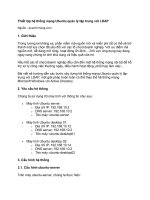
Hộp thoại chính của MasterCAM Design như sau:
Hình 1.1: Màn hình chính MasterCAM Design 9.1
Trên hộp hội thoại chính có thanh công cụ Toolbar, các Menu chính, Menu phụ. Thanh công
cụ Toolbar bao gồm các ô nhỏ (nút) nằm trên đỉnh của màn hình MasterCAM 9.1. Những ô
nhỏ này chứa các biểu tượng hoặc số để ký hiệu chức năng của lệnh. Số ô nằm trên Toolbar
phụ thuộc vào kích cỡ và độ phân giải màn hình của máy tính, được ặc định hình thành trong
chương trình MasterCAM 9.1.
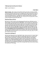
Hình 1.2: Thanh công cụ Toolbar
Để biết các chức năng của các nút trên thanh công cụ Toolbar, ta di chuyển con trỏ tới vị trí
các nút trên thanh công cụ và để yên con trỏ trên nút vài giây, MasterCAM sẽ hiện tên của nút
đó.
II. Các Menu chính của MasterCAM Design:
1. ANALYZE:
Dùng để kiểm tra tất cả thông tin của chi tiết thiết kế gồm: point, contour,
only, between, pts, angle, dynamic, area/volume, number, chain, syrface. Các
thông tin này giúp ta kiểm tra đặc tính của ácc đối tượng trong quá trình thiết
kế.
The Analyze menu gives you options for viewing data about entities and, in
some cases, editing the data. When the construction plane is set to 3D,
Mastercam calculates data using absolute, or world, coordinates relative to the
system origin (0,0,0). In any other construction mode, the system calculates
data using coordinates relative to the current Cplane.
You can access the Analyze menu by choosing Analyze from the Main Menu.
Click on the topics below for more information.
Angle:
- Analyzing the angle between two lines
1. Choose Main Menu, Analyze, Angle.
2. Select two lines. In the prompt area, Mastercam displays the value of the angles
formed by the lines.
Note: The first value is the smaller of the two angles formed by the lines; the second value
is the supplementary angle.
3. Repeat step 2 to analyze additional pairs of lines.
4. Press [Esc] to exit the function.
- Analyzing the distance and angle between two points
1. Choose Main Menu, Analyze, Between pts.
2. Enter two points in the graphics window. In the prompt area, Mastercam displays the
coordinates of the points and the distance (2D and 3D) and angle between the points.
3. Repeat step 2 to analyze additional pairs of points.
4. Press [Esc] to exit the function.
Attribute data:
- Analyzing an entity by number
Mastercam assigns a unique number to each entity in the file, which provides a useful
method for referencing entities.
1. Choose Main Menu, Analyze, Number.
2. In the prompt area, enter the number of the entity to analyze. Mastercam displays
data about the entity in the prompt area or in a dialog box, depending on the Edit option on
the Analyze Entity menu.
3. To analyze additional entities by number, choose Number on the Analyze Entity
menu and enter the entity number in the prompt area.
4. Press [Esc] to exit the function.
- Analyzing entities of a defined type
You can limit the entities that are selectable by defining allowable entity types and/or
attributes using the Only menu. Doing so reduces your chance of selecting the wrong entity
to analyze, which is useful when you make your selection in complex geometry.
1. Choose Main Menu, Analyze, Only.
2. Use the Only menu to define your selection.
3. Select an entity. Mastercam displays data about the entity in the prompt area or in a
dialog box, depending on the Edit option on the Analyze Entity menu.
4. Repeat steps 2 and 3 to analyze additional entities of the defined type.
Note: To redefine the type of entity to analyze, choose Only from the Analyze Entity menu.
5. Press [Esc] to exit the function.
- Analyzing entity and attribute data
1. Choose Main Menu, Analyze.
2. Select an entity in the graphics window. Mastercam displays data about the entity in
the prompt area.
Note: If the Edit option on the Analyze Entity menu is set to Y, Mastercam displays the
data in a dialog box. Some of the data may be editable.
3. Repeat step 2 to analyze additional entities.
4. Press [Esc] to exit the function.
Chains:
- Analyze Chain dialog box
The Analyze Chain dialog box lets you select the problems that you want Mastercam to look
for in selected chains. Go to this dialog box by selecting Analyze, Chain from the Main
Menu, or by right-clicking in the Chain Manager dialog box; from the right-click menu,
select Analyze all or Analyze single. See the related topics below for more information.
You can set the following fields:
Display (Overlapping entities) searches for overlapping entities. Mastercam marks the
approximate overlap positions with red circles. You set the degree of overlap to search for
by choosing Quick or Thorough.
Quick searches for adjacent overlapping entities only. You must select Display
(Overlapping entities) to enable this option. This search takes less time to process than
Thorough.
Thorough searches for all overlapping entities. You must select Display (Overlapping
entities) to enable this option. This search takes longer to process than Quick.
Display (Direction reversal) searches for positions where the chain reverses direction by a
value greater than the minimum angle value. Mastercam marks direction reversals with
yellow points.
Minimum angle sets the minimum angle that Mastercam uses to detect direction reversals.
Mastercam does not detect direction reversals with a smaller angle than the minimum angle
value. You must select Display (Direction reversal) to enable this option.
Display (Short entities) searches for short entities. A short entity has a length smaller than
the maximum length value. Mastercam marks short entities with blue circles.
Max length sets the maximum length that defines a short entity. Any entity that exceeds the
maximum length is no longer considered a short entity. You must select Display (Short
entities) to enable this option.
Display arrow at start of each chain displays an arrow at the start of each chain, which
serves as a good indicator of gaps in the chain.
Create geometry in problem areas creates geometry in problem areas, depending on what
options you select for use in analyzing the chains. This geometry helps you zoom in on
problem areas in order to fix them. For example, Mastercam creates red arcs (circles) for
overlapping entities, yellow point entities for direction reversals, and blue arcs (circles) for
short entities.
- Analyzing chains for coordinate data
1. Choose Main Menu, Analyze, Contour.
2. Select one or more chains, then choose Done.
3. Set Contour type to 2D to analyze the boundary for 2D data or 3D to analyze the
boundary for 3D data.
Note: Choose 3D if your selection in step 2 contained spline entities.
4. Set Offset direction to Off and ignore all other options on the Analyze Contour
Parameters dialog box.
Note: This step does not apply to Mastercam Design users since the only parameters
available are those pertaining to Contour type (set in step 3).
5. Choose OK to close the dialog box.
6. In the prompt area, type a comment for the report (optional), then press [Enter].
7. View the data, then close the window.
Note: Press [Alt+P] to print the data.
Analyzing chains for offset data
1. Choose Main Menu, Analyze, Contour.
2. Select one or more chains, then choose Done.
3. Set Contour type to 2D.
4. Set Offset Distance to a value other than zero.
5. Set Offset direction to Left or Right.
6. Set the remaining parameters on the Analyze Contour Parameters dialog box, then
choose OK.
7. In the prompt area, type a comment for the report (optional), then press [Enter].
8. View the data, then close the window.
Notes:
¨ To print the data, press [Alt+P] before closing the file in step 8.
¨ This function is not available in Mastercam Design.
¨ To analyze spline entities for offset data, you must first break them into line or arc
segments. For more information, see Breaking a spline into multiple line segments and
Breaking 2D splines into arc and line segments.
- Analyzing problems in chains
In addition to analyzing chains for overlapping entities, direction reversals, and short
entities, you can create geometry to mark problem areas, which helps you identify these
areas in order to fix them.
1. Choose Main Menu, Analyze, Chain.
2. Select one or more chains, then choose Done.
Note: To avoid missing overlapping or short entities, we recommend that you use the
Window chaining method.
3. Set display options for the types of problems you want to locate in the chains, then
choose OK.
4. In the prompt area, Mastercam reports the number of each type of problem it finds
and highlights the problem areas in the graphics window. Press [Enter] to exit the function
after reviewing the data.
Curves:
- Analyzing 2D curve area:
1. Choose Main Menu, Analyze, Area/volume, 2D area.
2. Select one or more closed, flat chains, then choose Done.
Note: Nested chains are allowed and are treated as holes whose area is subtracted from the
area of the outermost boundary. Disjoint chains are not allowed.
3. Enter a value for Chord height.
Note: This value sets the preciseness with which Mastercam analyzes the area defined by
the selected entities. A smaller value results in a more precise analysis and a more accurate
calculation of area but with the possibility of a longer processing time.
4. View the data, then choose OK to close the dialog box.
- Analyzing a curve, surface, or solid face at any position
Mastercam displays different data depending on the type of entity you select.
¨ For lines, Mastercam displays the point and tangent coordinates.
¨ For arcs and splines, Mastercam displays the point and tangent coordinates and the
radius of curvature.
¨ For surfaces and solid faces, Mastercam displays the point coordinates, the normal
coordinates, and the minimum radius of curvature.
1. Choose Main Menu, Analyze, Dynamic.
2. Select a line, arc, spline, surface, or solid face. In the graphics window, Mastercam
displays a dynamic arrow on the selected entity.
3. Use the mouse to move the base of the arrow to positions that you want to analyze
on the entity. In the prompt area, Mastercam displays data relative to the arrow position.
4. Press [Esc] to stop analyzing the selected entity.
5. Repeat steps 2 through 4 to analyze additional entities.
6. Press [Esc] to exit the function.
- Analyzing chains for coordinate data
1. Choose Main Menu, Analyze, Contour.
2. Select one or more chains, then choose Done.
3. Set Contour type to 2D to analyze the boundary for 2D data or 3D to analyze the
boundary for 3D data.
Note: Choose 3D if your selection in step 2 contained spline entities.
4. Set Offset direction to Off and ignore all other options on the Analyze Contour
Parameters dialog box.
Note: This step does not apply to Mastercam Design users since the only parameters
available are those pertaining to Contour type (set in step 3).
5. Choose OK to close the dialog box.
6. In the prompt area, type a comment for the report (optional), then press [Enter].
7. View the data, then close the window.
Note: Press [Alt+P] to print the data.
-Analyzing entity and attribute data
1. Choose Main Menu, Analyze.
2. Select an entity in the graphics window. Mastercam displays data about the entity in
the prompt area.
Note: If the Edit option on the Analyze Entity menu is set to Y, Mastercam displays the
data in a dialog box. Some of the data may be editable.
3. Repeat step 2 to analyze additional entities.
4. Press [Esc] to exit the function.
Analyzing the angle between two lines
1. Choose Main Menu, Analyze, Angle.
2. Select two lines. In the prompt area, Mastercam displays the value of the angles
formed by the lines.
Note: The first value is the smaller of the two angles formed by the lines; the second value
is the supplementary angle.
3. Repeat step 2 to analyze additional pairs of lines.
4. Press [Esc] to exit the function.
Entity data:
- Analyzing an entity by number
Mastercam assigns a unique number to each entity in the file, which provides a useful
method for referencing entities.
1. Choose Main Menu, Analyze, Number.
2. In the prompt area, enter the number of the entity to analyze. Mastercam displays
data about the entity in the prompt area or in a dialog box, depending on the Edit option on
the Analyze Entity menu.
3. To analyze additional entities by number, choose Number on the Analyze Entity
menu and enter the entity number in the prompt area.
4. Press [Esc] to exit the function.
- Analyzing entities of a defined type
You can limit the entities that are selectable by defining allowable entity types and/or
attributes using the Only menu. Doing so reduces your chance of selecting the wrong entity
to analyze, which is useful when you make your selection in complex geometry.
1. Choose Main Menu, Analyze, Only.
2. Use the Only menu to define your selection.
3. Select an entity. Mastercam displays data about the entity in the prompt area or in a
dialog box, depending on the Edit option on the Analyze Entity menu.
4. Repeat steps 2 and 3 to analyze additional entities of the defined type.
Note: To redefine the type of entity to analyze, choose Only from the Analyze Entity menu.
5. Press [Esc] to exit the function.
- Analyzing entity and attribute data
1. Choose Main Menu, Analyze.
2. Select an entity in the graphics window. Mastercam displays data about the entity in
the prompt area.
Note: If the Edit option on the Analyze Entity menu is set to Y, Mastercam displays the
data in a dialog box. Some of the data may be editable.
3. Repeat step 2 to analyze additional entities.
4. Press [Esc] to exit the function.
Points:
Analyzing entity and attribute data
1. Choose Main Menu, Analyze.
2. Select an entity in the graphics window. Mastercam displays data about the entity in
the prompt area.
Note: If the Edit option on the Analyze Entity menu is set to Y, Mastercam displays the
data in a dialog box. Some of the data may be editable.
3. Repeat step 2 to analyze additional entities.
4. Press [Esc] to exit the function.
Analyzing the coordinates of a point
1. Choose Main Menu, Analyze, Point.
2. Enter a point in the graphics window. In the prompt area, Mastercam displays the
coordinates of the point.
3. Repeat step 2 to analyze additional points.
4. Press [Esc] to exit the function.
CREATE: