Tài liệu Windows 7 Resource Kit- P6 docx
Bạn đang xem bản rút gọn của tài liệu. Xem và tải ngay bản đầy đủ của tài liệu tại đây (997.19 KB, 50 trang )
Editing a Task Sequence CHAPTER 6
203
Editing a Task Sequence
In MDT 2010, the task sequence is a list of tasks to run during deployment. However, it’s not a
linear list of tasks like a batch script. The task sequence is organized into groups and specifies
conditions, or filters, that can prevent tasks and entire groups from running in certain situations.
MDT 2010 uses a Task Sequencer to run the task sequence. The Task Sequencer runs the
task sequence from top to bottom in the order specified. Each task in the sequence is a step,
and steps can be organized into groups and subgroups. When you create a task sequence in
Deployment Workbench, you can choose a task sequence template. A key feature of the task
sequence is that it stores state data, or variables, on the destination computer. These variables
persist, even across reboots. The Task Sequencer can then use these variables to test conditions
and possibly filter tasks or groups. The Task Sequencer also can restart the computer and
gracefully continue the task sequence where it left off. These are important characteristics
when driving a deployment process from beginning to end.
Task sequences contain the following types of items:
n
Steps Steps are commands that the Task Sequencer runs during the sequence, such
as partitioning the disk, capturing user state, and installing the operating system.
Within a task sequence, steps do the actual work. In the task sequence templates pro-
vided by MDT 2010, most steps are commands that run scripts.
n
Groups The task sequence steps can be organized into groups, which are folders that
can contain subgroups and steps. Groups can be nested as necessary. For example, the
default task sequence puts steps in groups by phase and deployment type.
You can filter both steps and groups, including the groups and steps that they contain,
based on conditions that you specify. Groups are especially useful for filtering because you
can run an entire collection of steps based on a condition, such as the deployment phase or
type of deployment.
To edit a task sequence, perform the following steps:
1. In the Deployment Workbench console tree, click Task Sequences (or a subfolder) in
your deployment share.
2. In the details pane, right-click the task sequence you want to edit and then click
Properties.
3. Click the Task Sequence tab, as shown here, edit the task sequence as described in
Table 6-5, and then click OK. For more information about settings on the Properties
and Options tabs, see the sections titled “Configuring Group and Task Properties” and
“Configuring the Options Tab“ later in this chapter.
Please purchase PDF Split-Merge on www.verypdf.com to remove this watermark.
CHAPTER 6 Developing Disk Images
204
TABLE 6-5 Editing a Task Sequence
TO USE THESE STEPS
Add a group In the task sequence, select the item beneath which you want
to create a new group, click Add, and then click New Group.
Deployment Workbench creates and selects a new group
called New Group.
Add a step In the task sequence, select the item beneath which you want
to create a new step and click Add. Then choose the type of
step that you want to create by clicking General and then
choosing one of the following (MDT 2010 supports more
steps than those listed here, but they are already in the task
sequence or are primarily for server deployment):
n
Run Command Line
n
Set Task Sequence Variable
n
Run Command Line As
Deployment Workbench creates and selects a new step with
a name relating to the type of step you’re creating.
Add a reboot In the task sequence, select the item beneath which you want
to add a reboot, click Add, click General, and then click
Restart Computer. Deployment Workbench creates and
selects a new task that restarts the destination computer.
Please purchase PDF Split-Merge on www.verypdf.com to remove this watermark.
Editing a Task Sequence CHAPTER 6
205
TO USE THESE STEPS
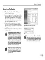
Add an application In the task sequence, select the item beneath which you
want to add an application installation, click Add, click
General, and then click Install Application. Then select the
Install Application step you just added, and on the Properties
tab, click Install A Single Application. Choose the application
you want to install from the Application To Install list.
iMpoRtAnt If you install antivirus software as part of the task sequence, be sure to
carefully test how the antivirus software interacts with the deployment process before
moving to a production environment. Antivirus software can prevent MDT 2010 from
successfully deploying Windows 7 and applications. If necessary, you can always disable
the antivirus software and then re-enable it at the end of the task sequence.
To edit an item in a task sequence, select the item you want to work with and then edit the
settings in the right pane.
note MDT 2010 includes a variety of special steps, such as the Enable BitLocker task or
Install Operating System step, that you can configure. You change settings for these steps
by selecting the step in the left pane and then configuring the step on the Properties tab.
In general, the most interesting steps to configure are Validate (under Validation and under
Preinstall\New Computer Only), Format and Partition Disk (under Preinstall\New Computer
Only), Install Operating System (under Install), Apply Network Settings (under State
Restore), and Enable BitLocker (under State Restore).
To remove an item in a task sequence, select the item you want to work with and then click
Remove. If a group is removed, Deployment Workbench removes the group and everything it
contains, including subgroups and tasks.
To reorder an item in a task sequence, select the item you want to work with and then
click Up or Down to change its position within the task sequence. During deployment, the
Windows Deployment Wizard runs the tasks from top to bottom in the order specified.
Configuring Group and Task Properties
In the task sequence, every group and step has a Properties tab. Each group and step has a
name and description that you can edit on the Properties tab. The Run Command Line and
Run Command Line As steps also have a command line and a starting folder location that you
can edit. Other steps have additional properties depending on the type of step. The following
list describes what you see on the Properties tab:
n
Type The Type box indicates the type of step. You cannot change the type.
Please purchase PDF Split-Merge on www.verypdf.com to remove this watermark.
CHAPTER 6 Developing Disk Images
206
n
Name In the Name box, type a short, descriptive name for the group or step. During
deployment, this name appears in the status window of the Task Sequencer.
n
Description In the Description box, type a description of the group or step.
n
Command Line (Run Command Line and Run Command Line As tasks only) In
the Command Line box, type the command to run at this step in the task sequence.
Include any command-line arguments. Environment variables are also permitted in
command lines.
n
Start In (steps only) In the Start In box, type the path in which to start the command.
This path specifies the current working directory for the command. If you do not
provide a path in this box, the paths in the Command Line box must be fully qualified
or the command must be in the path.
Configuring the Options Tab
Groups and tasks have the following settings on the Options tab (shown in Figure 6-5):
n
Disable This Step Select the Disable This Step check box to disable the step or
group, including all groups and steps that it contains.
n
Success Codes (steps only) List the return codes that indicate successful comple-
tion. The Windows Deployment Wizard determines whether a step completed success-
fully by comparing its return code to each code in the Success Codes box. If it finds a
match, the step completed successfully. A success code of 0 usually represents success-
ful completion. A success code of 3010 usually represents a successful completion with
a reboot required. Thus, most of the steps in the templates that MDT 2010 provides list
the success codes as 0 3010.
n
Continue On Error If an error occurs in the current step, select the Continue On
Error check box to continue with the next step in the task sequence. If you clear this
check box, the Windows Deployment Wizard stops processing and displays an error
message if the step or group does not complete successfully.
Additionally, on the Options tab, you can filter the group or steps based on conditions
specified in the Conditions list. If the condition evaluates to true, the group or step runs. If the
condition evaluates to false, the group (and all of the groups and steps that group contains)
or step does not run. See the following sections for more information about conditions you
can add to the Conditions list.
Please purchase PDF Split-Merge on www.verypdf.com to remove this watermark.
Editing a Task Sequence CHAPTER 6
207
FIGURE 6-5 The Options tab
Task Sequence Variables
Task sequence variables allow you to compare a variable to a static value using a variety of
conditions, such as equal, greater than, and less than. The Task Sequencer maintains numer-
ous variables that you can use in these tests. For example, the Task Sequencer defines a vari-
able called DeploymentMethod that indicates the method of deployment. One possible value
of DeploymentMethod is UNC. For a complete list of variables that the Task Sequencer main-
tains, see the Microsoft Deployment Toolkit Reference in the MDT 2010 documentation.
To add a variable to an item’s Conditions list, perform the following steps:
1. On the Options tab, click Add and then click Task Sequence Variable to display the Task
Sequence Variable Condition dialog box, shown here.
2. In the Variable box, type the name of the variable you want to test.
Please purchase PDF Split-Merge on www.verypdf.com to remove this watermark.
CHAPTER 6 Developing Disk Images
208
3. From the Conditions list, choose one of the following conditions:
•
Exists
•
Equals
•
Not equals
•
Greater than
•
Greater than or equals
•
Less than
•
Less than or equals
4. In the Value box, type the static value you want to compare to the variable using the
condition specified in the previous step.
if Statements
Use if statements to combine variables into bigger expressions. For example, create an if
statement that evaluates to true only if all the conditions it contains are true (the same as a
logical AND), or create an if statement that evaluates to true if any of the conditions it contains
are true (the same as a logical OR).
To add an if statement to an item’s Conditions list, perform the following steps:
1. On the Options tab, click Add and then click If Statement to display the If Statement
Properties dialog box, shown here.
2. In the If Statement Properties dialog box, choose one of the following options and
then click OK:
•
All conditions (AND)
•
Any conditions (OR)
•
None
3. From the Conditions list, select the if statement added in the previous step and then
add task sequence variables to it as described in the previous section.
If you choose All Conditions, all variables added must evaluate to true for the group or
step to run. If you choose Any Conditions, the group or task will run if any one of the vari-
ables added evaluates to true.
Please purchase PDF Split-Merge on www.verypdf.com to remove this watermark.
Editing a Task Sequence CHAPTER 6
209
note You can nest if statements to create complex logic. If you are familiar with Boolean
logic, represent Boolean expressions as if statements in the Conditions list.
Operating System Versions
The Task Sequencer allows you to filter steps and groups based on the computer’s current
operating system. For example, you can choose to run a preinstallation step only if the
destination computer is currently running Windows Vista SP1.
To add an operating system filter to an item’s Conditions list, perform the following steps:
1. On the Options tab, click Add, and then click Operating System Version to display the
Task Sequence OS Condition dialog box.
2. From the Architecture list, click either X86 or X64.
3. From the Operating System list, choose an operating system version and a service pack
level.
4. From the Conditions list, choose one of the following conditions:
•
Equals
•
Not equals
•
Greater than
•
Greater than or equals
•
Less than
•
Less than or equals
WMI Queries
The Task Sequencer allows you to filter steps and groups based on WMI queries. The WMI
query must return a collection. If the collection is empty, the result evaluates to false. If the
collection is not empty, the result evaluates to true. The following are some sample WMI
queries you could use to filter steps in the task sequence:
n
SELECT * FROM Win32_ComputerSystem WHERE Manufacturer = ‘Dell Computer
Corporation’. This is true only if WMI reports the computer’s manufacturer as Dell
Computer Corporation.
n
SELECT * FROM Win32_OperatingSystem WHERE OSLanguage = ‘1033’. This is true
only if WMI reports the operating system language as 1033.
n
SELECT * FROM Win32_Service WHERE Name = ‘WinMgmt’. This is true only if the
WinMgmt service is available.
n
SELECT * FROM Win32_Processor WHERE DeviceID = ‘CPU0’ AND Architecture = ‘0’.
This is true only if the processor architecture is x86.
n
SELECT * FROM Win32_Directory WHERE Name = ‘D:\Somefolder’. This is true only if
D:\Somefolder exists on the computer.
Please purchase PDF Split-Merge on www.verypdf.com to remove this watermark.
CHAPTER 6 Developing Disk Images
210
To add a WMI query to an item’s Conditions list, perform the following steps:
1. On the Options tab, click Add and then click Query WMI to display the Task Sequence
WMI Condition dialog box.
2. In the WMI Namespace box, type the WMI namespace in which to run the query, as
shown here. The default namespace is root\cimv2.
3. In the WQL Query box, type the WMI query.
Updating the Deployment Share
The Windows AIK 2.0 comes with Windows PE 3.0, so no additional files are necessary to cre-
ate Windows PE boot images for MDT 2010. When you update your deployment share in the
Deployment Workbench, MDT 2010 automatically generates the following custom Windows
PE images (here platform is x86 or x64):
n
Lite Touch Windows PE (platform) .wim file
n
LiteTouchPE_platform.iso
If you want, you can configure the deployment share to also generate the following
Windows PE images:
n
Generic Windows PE (platform)
n
Generic_platform.iso
You don’t need to manually customize Windows PE to add network interface card (NIC)
device drivers to it. Deployment Workbench automatically adds the NIC device drivers that
you add to the deployment share to the Windows PE boot images. You have the additional
option of automatically adding video and system device drivers from the deployment share
to the Windows PE boot images. You can also perform additional customizations of your
Windows PE images. For example, you can customize the background bitmap, add additional
directories, and increase the scratch space size from its default value of 32 megabytes (MB) up
to a maximum of 512 MB if needed. To learn more about customizing Windows PE, see the
Windows Preinstallation Environment User’s Guide for Windows 7 in the Windows AIK.
Please purchase PDF Split-Merge on www.verypdf.com to remove this watermark.
Editing a Task Sequence CHAPTER 6
211
Updating a deployment share causes Deployment Workbench to update its configuration
files, source files, and Windows PE images. Deployment Workbench updates the deployment
share’s files and generates the Windows PE boot images when you update the deployment
share, not when you create it. Deployment Workbench stores these boot images in the de-
ployment share’s \Boot folder. After you have updated the deployment share and generated
Windows PE images, you can add the .wim image file to Windows Deployment Services. If you
want, you can burn the Windows PE .iso images to CD or DVD media by using third-party CD/
DVD-burning software. Windows Deployment Services is the best way to start the Windows
PE boot images on lab computers. Updating the boot images is faster than burning media,
and booting destination computers is quicker. For more information, see Chapter 10.
note You must use the same platform edition of Windows PE to start computers for
installing each platform edition of Windows. In other words, you must start destination
computers using a x86 edition of Windows PE to install a x86 edition of Windows 7.
Likewise, you must use a x64 edition of Windows PE to install a x64 edition of Windows 7.
If you use mismatched editions, you might see errors indicating that the image is for a
different type of computer. Deployment Workbench automatically chooses the correct
platform edition of Windows PE to match the operating system you’re deploying.
To configure a deployment share for imaging in the lab, perform the following steps:
1. In the Deployment Workbench console tree, click Deployment Shares.
2. In the details pane, right-click the deployment share you want to configure and then
click Properties.
3. Click the General tab and then choose the platforms that the deployment share sup-
ports. To indicate that the deployment share supports the x86 platform, select the x86
check box. To indicate that the deployment share supports the x64 platform, select the
x64 check box. This option determines the platforms for which Deployment Workbench
generates Windows PE boot images.
4. Click the Rules tab and then edit the deployment share’s settings. These settings are
located in CustomSettings.ini, which is located in the deployment share’s Control
folder. For more information about the settings that you can configure on this tab, see
the Microsoft Deployment Toolkit Reference in MDT 2010.
5. Click the Windows PE Settings (platform) tab for each platform and edit the settings
described in Table 6-6, as shown on the following page. Then, click OK.
Please purchase PDF Split-Merge on www.verypdf.com to remove this watermark.
CHAPTER 6 Developing Disk Images
212
TABLE 6-6 Windows PE Settings Tab
AREA SETTINGS
Images to
Generate
Generate A Lite Touch Windows PE WIM file Select this
option to generate a customized WIM file that you can use to
perform LTI using Windows Deployment Services (this option is
selected by default and cannot be cleared).
Generate A Lite Touch Bootable ISO Image Select this option
to generate a bootable customized Windows PE ISO image that
you can use to perform LTI by starting your destination computers
manually (this option is selected by default).
Generate A Generic Windows PE WIM file Select this option
to generate a generic WIM file that you can use to perform LTI
using Windows Deployment Services.
Generate A Generic Bootable ISO Image Select this option
to generate a bootable generic Windows PE ISO image that you
can use to perform LTI by starting your destination computers
manually.
Windows PE
Customizations
Custom Background Bitmap File Type the path and file name
of a bitmap file to use as the Windows PE background.
Extra Directory To Add Type the path of a folder containing ex-
tra files and subfolders to add to the Windows PE bootable images.
Scratch Space Size Select the size of the scratch space for your
Windows PE image. The available values are 32, 64, 128, 256, and
512 MB, with 32 being the default.
Please purchase PDF Split-Merge on www.verypdf.com to remove this watermark.
Editing a Task Sequence CHAPTER 6
213
6. Click the Windows PE Components (platform) tab for each platform and edit the
settings described in Table 6-7, as shown here, and then click OK.
TABLE 6-7 Windows PE Components Tab
AREA SETTINGS
Feature Packs ADO Select this option to add the Microsoft ActiveX Data
Objects (ADO) optional feature to the Windows PE bootable
images.
Optional Fonts Select the font support to add to the Windows PE boot images
that Deployment Workbench generates. You must add these
fonts when performing an LTI deployment of Windows Vista
images when the setup files are Japanese, Korean, or Chinese.
The Optional Fonts area provides the following options:
n
Chinese (ZH-CN)
n
Chinese (ZH-HK)
n
Chinese (ZH-TW)
n
Japanese (JA-JP)
n
Korean (KO-KR)
Adding additional fonts to Windows PE boot images increases
the size of the images. Add additional fonts only if necessary.
Please purchase PDF Split-Merge on www.verypdf.com to remove this watermark.
CHAPTER 6 Developing Disk Images
214
AREA SETTINGS
Driver Injection Selection Profile Use this list box to choose one of the follow-
ing selection profiles to include the appropriate device drivers in
your Windows PE images:
n
Everything Includes all folders from all nodes in
Deployment Workbench. This selection profile includes all
applications, operating systems, device drivers, operating
system packages, and task sequences.
n
All Drivers Includes all folders from the Out-Of-Box
Drivers node in Deployment Workbench. This selection
profile includes all device drivers.
n
All Drivers And Packages Includes all folders from the
Applications and Out-Of-Box Drivers nodes in Deployment
Workbench. This selection profile includes all applications
and device drivers.
n
Nothing Includes no folders in Deployment Workbench.
This selection profile includes no items.
n
Sample A sample selection profile that illustrates how to
select a subset of the items and include all folders from the
Packages and Task Sequences nodes in Deployment Work-
bench. This selection profile includes all operating system
packages and task sequences.
note If you have created any custom selection profiles,
these will also be available for selection here.
Selection profiles are new in MDT 2010 and allow you to select
one or more folders in Deployment Workbench that contain
one or more items in Deployment Workbench, including ap-
plications, device drivers, operating systems, operating system
packages, and task sequences. For more information concerning
selection profiles, see the topic “Managing Selection Profiles” in
the MDT 2010 documentation.
Include All Drivers From The Selected Driver Group Select
this option if you want to include all the device drivers in the
selection profile you specified in the Selection Profile list box.
Include Only Drivers Of The Following Types Select this op-
tion to include only specific types of device drivers in the selec-
tion profile you specified in the Selection Profile list box. If you
select this option, you can select one or more of the following:
Please purchase PDF Split-Merge on www.verypdf.com to remove this watermark.
Editing a Task Sequence CHAPTER 6
215
AREA SETTINGS
n
Include All Network Drivers In The Selected Group
Select this option to inject all the device drivers in the
selection profile specified in the Selection profile list box.
n
Include All Mass Storage Drivers In The Selected
Group Select this option to inject all mass storage drivers
found in the deployment share into the Windows PE boot
images.
n
Include All Video Drivers In The Selected Group Select
this option to inject all video drivers found in the deploy-
ment share into the Windows PE boot images.
n
Include All System-Class Drivers In The Selected
Group Select this option to inject all system drivers (such
as motherboard drivers) in the deployment share into the
Windows PE boot images.
After creating and configuring a deployment share in Deployment Workbench, you must
update it to update the deployment share's configuration files and generate Windows PE
boot images in the deployment share's \Boot folder. Deployment Workbench always gen-
erates .wim image files, which you can use to start destination computers using Windows
Deployment Services. Choose to generate only the Windows PE bootable ISO images that are
actually required. If you limit the number of images generated, the updating process is faster.
To update a deployment share, perform the following steps:
1. In the Deployment Workbench console tree, click Deployment Shares.
2. In the details pane, right-click the deployment share you want to configure and then
click Update.
3. On the Options page of the Update Deployment Share Wizard, shown on the following
page, select one of the following options:
•
Optimize The Boot Image Updating Process Select this option to update
existing versions of the image files in the deployment share. Choosing this option
reduces the amount of time required to update the boot images. If you select this
option, you can also select Compress The Boot Image Contents To Recover Space
Used By Removed Or Modified Content if desired. Selecting this suboption reduces
the size of the boot images but may increase the time needed to generate the
images.
•
Completely Regenerate The Boot Images Select this option to create a new
version of all the image files in the deployment share. You can choose this option
when you want to force the creation of new images. Note that this can take some
time to complete.
Please purchase PDF Split-Merge on www.verypdf.com to remove this watermark.
CHAPTER 6 Developing Disk Images
216
4. Finish the wizard. Depending on how your deployment share is configured and the
options you selected in the Update Deployment Share Wizard, generating Windows PE
boot images may take some time to complete.
After the deployment share has been updated, Windows PE boot images and other files
will be present in the \Boot folder of the deployment share (see Figure 6-6).
FIGURE 6-6 \Boot folder of updated deployment share showing Windows PE boot images that were
generated
Please purchase PDF Split-Merge on www.verypdf.com to remove this watermark.
Capturing a Disk Image for LTI CHAPTER 6
217
iMpoRtAnt You must update your deployment share if you make changes to any the
settings on the properties sheet of your deployment share. The Windows PE boot images
will not contain your updated settings until you update your deployment share.
Capturing a Disk Image for LTI
In MDT 2010, installing a build and capturing an image is essentially an LTI deployment that
ends with the Windows Deployment Wizard capturing an image of the destination computer.
When you create a deployment share, Deployment Workbench provides the option of
prompting to capture an image (the Ask If An Image Should Be Captured check box). You
must enable this option, as described in the section titled “Creating and Configuring a
Deployment Share” earlier in this chapter.
Then, when you install the build on the destination lab computer, the Windows Deployment
Wizard asks whether you want to capture an image after installation is complete. The wizard
also allows you to specify a destination for the image. The default destination is the \Captures
folder in the deployment share, and the default file name is task sequence.wim, where task
sequence is the ID of the task sequence you installed.
To capture an image, start a lab computer using the Windows PE boot image generated
by updating the deployment share. Start the Windows PE boot image in either of two ways.
One way is to burn the .iso images to a DVD. This process is slow and tedious. These ISO
image files reside in the \Boot folder of the deployment share. The other way is to add the
LiteTouchPE_x86.wim or LiteTouchPE_x64.wim image files to the Boot Images item of a
Windows Deployment Services server. The .wim image files are in the \Boot folder of the
deployment share. For more information about installing and configuring Windows Deploy-
ment Services, see Chapter 10.
To capture an image using the Windows Deployment Wizard, perform the following steps:
1. Start the lab computer using the Windows PE boot image that you created in the
section titled “Updating the Deployment Share“ earlier in this chapter. You can start
this boot image by burning the .iso file to CD or DVD media or by adding the .wim file
to Windows Deployment Services. For more information about Windows Deployment
Services, see Chapter 10.
2. In the Welcome Windows Deployment dialog box, click Run The Deployment Wizard
To Install A New Operating System.
3. In the User Credentials dialog box, type the credentials necessary to connect to
the deployment share (user name, domain, and password) and then click OK. The
Windows Deployment Wizard starts automatically. To capture an image using the
Windows Deployment Wizard, you must use an account that has Read and Write
access to the deployment share, such as an account that is a member of the local
Administrators group on the computer that contains the deployment share.
Please purchase PDF Split-Merge on www.verypdf.com to remove this watermark.
CHAPTER 6 Developing Disk Images
218
4. On the Select A Task Sequence To Execute On This Computer page, choose a task
sequence to run from the list of available task sequences and then click Next.
5. On the Configure The Computer Name page, type a computer name or accept the
default and then click Next. The default, randomly generated computer name is rea-
sonable because the computer name will change during deployment to the production
environment.
6. On the Join The Computer To A Domain Or Workgroup page, click Join A Workgroup.
In the Workgroup box, type a workgroup name or accept the default and then click
Next. If you join the computer to a domain, the Windows Deployment Wizard does not
prompt you to capture an image.
7. On the Specify Whether To Restore User Data page, select Do Not Restore User Data
And Settings and then click Next.
8. On the Packages page (if displayed), choose the packages, such as software updates
and language packs, that you want to install on the image and then click Next.
9. On the Locale Selection page, choose your locale and keyboard layout and then click
Next. Your choice here is irrelevant, because the Windows Deployment Wizard will
configure the locale and keyboard layouts during deployment to the production
environment.
10. On the Select The Time Zone page, select a time zone and then click Next. Your choice
here is irrelevant, because the Windows Deployment Wizard will configure the time
zone during deployment to the production environment.
11. On the Select One Or More Applications To Install page (if displayed), select the check
box next to each application that you want to install on the image and then click Next.
12. In the Specify Whether To Capture An Image page, select Capture An Image Of This
Reference Computer. In the Location box, type the Universal Naming Convention
(UNC) path of the folder in which to store the image or accept the default capture
location. In the File Name box, type the file name of the image or accept the default
file name for the captured image. The default UNC path is the \Captures folder of the
deployment share; the default image file name is the ID of the task sequence being
installed. Click Next.
12. Click Next, then on the Ready To Begin page, click Begin.
After you click Begin, the Task Sequencer begins running the build’s task sequence. By
default, it begins by partitioning and formatting the hard disk. Then it installs and configures
the operating system, runs Sysprep to prepare the computer for imaging, and restarts the
computer in Windows PE to capture the image. The Windows Deployment Wizard stores the
captured image in the folder specified on the Specify Whether To Capture An Image page,
which is the deployment share’s \Captures folder by default. After capturing the image, you
can add it to the deployment share as a custom image by using the steps described in the
section titled “Creating and Configuring a Deployment Share“ earlier in this chapter. For more
information about deploying your custom Windows 7 image, see Chapter 12.
Please purchase PDF Split-Merge on www.verypdf.com to remove this watermark.
Preparing Images Manually CHAPTER 6
219
Preparing Images Manually
The deployment share tells Windows Setup how to install and configure Windows 7 on the
destination computers. It includes the settings (answer file) as well as device drivers and pack-
ages that you want to add to the operating system. It might also contain applications that you
want to install.
A common way to deliver operating systems to users is to create an image of the desired
configuration. This is particularly true when the deployment share includes other files, such as
applications. Creating an image that you install on each destination computer is quicker and
more efficient than installing the uncustomized Windows 7 image and then installing applica-
tions on each destination computer.
Sysprep prepares a Windows 7 installation for imaging or delivery to end users. Sysprep
removes all user-specific information from a system and resets any system-specific security
identifiers (SIDs) to allow the system to be duplicated. Once duplicated, systems using the
duplicated image will register their own SIDs with the domain in which they are deployed.
Sysprep has several command-line options to control its behavior, listed in Table 6-8.
TABLE 6-8 Sysprep Command-Line Options
OPTION DESCRIPTION
/audit Restarts the computer into audit mode. In audit mode, you can
add additional drivers or applications to Windows Vista. You can
also test an installation of Windows Vista before it is sent to an
end user. If you specify an unattended Windows Vista setup file,
the audit mode of Windows Setup runs the auditSystem and
auditUser configuration passes.
/generalize Prepares the Windows installation to be imaged. If you specify
this option, all unique system information is removed from
the Windows installation. The system’s SID is reset, any System
Restore points are cleared, and event logs are deleted. The next
time the computer starts, the specialize configuration pass runs.
A new SID is created, and the clock for Windows activation resets
(if the clock has not already been reset three times).
/oobe Restarts the computer into Windows Welcome mode. Windows
Welcome allows end users to customize the Windows operating
system, create user accounts, name the computer, and complete
other tasks. Any settings in the oobeSystem configuration pass
in an answer file are processed immediately before Windows
Welcome starts.
/reboot Restarts the computer. Use this option to audit the computer and
to verify that the first-run experience operates correctly.
/shutdown Shuts down the computer after Sysprep completes.
Please purchase PDF Split-Merge on www.verypdf.com to remove this watermark.
CHAPTER 6 Developing Disk Images
220
OPTION DESCRIPTION
/quiet Runs Sysprep without displaying on-screen confirmation
messages. Use this option if you automate Sysprep.
/quit Closes Sysprep after running the specified commands.
/unattend: answerfile Applies settings in an answer file to Windows during unattended
installation. You can create this answer file in Windows SIM.
answerfile Specifies the path and file name of the answer file to use.
When you create a Windows 7 installation that you plan to image, you then use Sysprep to
generalize the system. The following command generalizes the system and prepares it to run
the Windows Welcome Wizard on the next restart.
sysprep /oobe /generalize
Most organizations use this command. If you are a system builder or an Original Equipment
Manufacturer (OEM), however, you can also use Sysprep to create build-to-order systems. The
following command lets you place a system into audit mode on the next restart, wherein you
can install additional applications and modify configurations.
sysprep /audit /generalize /reboot
The following command then completes the customization by preparing the system to run
the Windows Welcome on the next boot, which is a typical requirement in a retail environment.
sysprep /oobe
When all system preparations have been made, the system is ready for imaging. You can
use the ImageX command with the /FLAGS parameter to capture an image of the system. You
can then burn the image onto a DVD, import it into a deployment share, or leave it on the
system for use on the next system start.
Customizing Microsoft Deployment Toolkit
You can brand some features in MDT 2010. You can customize Deployment Workbench
and the Windows Deployment Wizard. For example, you can customize Workbench.xml in
C:\Program Files\Microsoft Deployment\Bin to change the text displayed in the Deployment
Workbench title bar and for each item in the console tree. Although it’s generally safe to
customize the <Name> tag in Workbench.xml, you should avoid changing other tags.
The LTI process is driven by .xml files called definition files. You can brand the entire LTI
process by customizing the following files, which are found in the \Scripts folder in your
deployment share:
n
BDD_Welcome_ENU.xml Customize this file to change the text displayed on the
Windows Deployment Wizard’s Welcome page.
Please purchase PDF Split-Merge on www.verypdf.com to remove this watermark.
Additional Resources CHAPTER 6
221
n
Credentials_ENU.xml Customize this file to change the text displayed in the User
Credentials dialog box.
n
DeployWiz_Definition_ENU.xml Customize this file to change the text for each
page displayed by the Windows Deployment Wizard.
n
Summary_Definition_ENU.xml Customize this file to change the text in the
Deployment Summary dialog box, which displays at the end of the LTI process.
Summary
The new installation architecture first introduced in Windows Vista and deployment tools
included in the Windows AIK make deploying Windows 7 in your organization easier than
deploying earlier versions of Windows. The new .wim file format makes it possible to deploy
highly compressed image files. Windows 7 helps reduce image count by removing hardware
and other dependencies from the image. Modularization in Windows 7 makes servicing
images easier than with legacy methods, so you no longer have to apply, customize, and
recapture an image to update it. The new answer file format, Unattend.xml, provides a more
flexible and consistent configuration. Finally, deployment tools in the Windows AIK 2.0
provide a robust way to create, customize, and manage Windows 7 images.
Although the Windows AIK 2.0 provides the basic tools for customizing and deploying
Windows 7, MDT 2010 provides a more flexible framework for deploying Windows 7 in
businesses. MDT 2010 enables you to create and customize multiple image builds. The frame-
work includes automation common to most businesses and is highly extensible to suit any
requirements. For example, by using MDT 2010 to deploy Windows 7, you can include custom
actions such as installing applications, packages, and drivers that are performed during
installation.
Additional Resources
These resources contain additional information and tools related to this chapter.
n
Chapter 3, “Deployment Platform,” includes information about the Windows 7 instal-
lation architecture, its key features and technologies, and how the various features
interact.
n
Chapter 4, “Planning Deployment,” includes information about installing and preparing
MDT 2010 for use. This chapter also describes how to use the MDT 2010 documentation.
n
Chapter 10, “Configuring Windows Deployment Services,” explains how to install
and configure Windows Deployment Services and how to add images to and deploy
images from Windows Deployment Services.
n
Chapter 11, “Using Volume Activation,” includes more information about Windows 7
product keys and volume activation.
Please purchase PDF Split-Merge on www.verypdf.com to remove this watermark.
CHAPTER 6 Developing Disk Images
222
n
Chapter 12, “Deploying with Microsoft Deployment Toolkit,” includes more information
about using MDT 2010 to deploy Windows 7 images in the production environment.
n
Microsoft Deployment Toolkit Reference in MDT 2010 lists the properties you can
configure in a deployment share.
n
Windows Automated Installation Kit User’s Guide for Windows 7 contains detailed
information about the tools and technologies included in the Windows AIK 2.0. This
guide is in the file Waik.chm in the Windows AIK 2.0.
Please purchase PDF Split-Merge on www.verypdf.com to remove this watermark.
223
CHAPTER 7
Migrating User State Data
n
Evaluating Migration Technologies 224
n
Using Windows Easy Transfer 226
n
Planning User State Migration Using USMT 230
n
Installing USMT 237
n
Understanding USMT Components 238
n
Developing Migration Files 240
n
Using USMT in Microsoft Deployment Toolkit 242
n
Summary 245
n
Additional Resources 246
O
perating system deployment always involves user state migration—the process of
migrating users’ documents and settings from one operating system to another.
Even when you don’t migrate user state during deployment, users will spend countless
hours trying to restore their preferences (such as desktop backgrounds, screensavers,
and themes). Because this manual process reduces user productivity and usually in-
creases support calls, organizations often choose to migrate some portion of user state
to new operating systems as they are deployed.
User satisfaction is another reason to elevate the importance of user state migration
in your project. Users are simply more satisfied and feel less overwhelmed when they
sit down in front of a new operating system and they don’t have to recover their prefer-
ences. The fact is that unsatisfied users can lead to poor post-implementation reviews
and can have negative consequences for future deployment projects. For example, user
dissatisfaction with previous projects can stall a deployment project that you know will
benefit the company in the long term. Keep the users happy.
This chapter helps you decide which user state migration tools best suit your environ-
ment. It then explores the User State Migration Tool (USMT) 4.0, including customizing and
automating the user state migration process. You’ll learn how to identify user state data,
how to plan the user state migration project, and how to execute the user state migration
using tools such as Windows scripting and Microsoft Deployment Toolkit 2010 (MDT 2010).
Please purchase PDF Split-Merge on www.verypdf.com to remove this watermark.
CHAPTER 7 Migrating User State Data
224
Evaluating Migration Technologies
Whether you decide to migrate user state individually, as part of a high-volume deployment
project, or not at all, you should evaluate the available options to ensure that you make the
best choices for your environment. The size and scope of the migration project factor into
your choice, as will the type and amount of user state data you choose to migrate.
The following sections describe the different options that Microsoft provides. Several
third-party products are also available for migrating user state. If you’re using MDT 2010 as
your deployment framework, Microsoft recommends that you use USMT to migrate user state
to Windows 7. USMT handles most common scenarios out of the box, and exceptional cases
are easy to configure. Additionally, MDT 2010 already includes the pre-deployment and post-
deployment logic for saving and restoring user state.
Windows Easy Transfer
Windows Easy Transfer is the Windows 7 equivalent of the Windows XP Files And Settings
Transfer Wizard. This tool leads the user through a series of pages to determine how much
data to migrate and which migration method to use (removable media, universal serial bus
(USB) cable connection, or network). Using Windows Easy Transfer is not appropriate in high-
volume deployment projects because it is a completely manual process. However, in bench
deployments, Windows Easy Transfer can be a viable tool for migrating user state on indi-
vidual computers.
note Windows Easy Transfer can transfer user state data using a special USB cable
available from most cable vendors. The Easy Transfer Cable includes circuitry that links two
computers using their USB ports and can transfer data at approximately 20 gigabytes (GB)
per hour.
User State Migration Tool
Use USMT to migrate user state in high-volume deployment projects. It can execute complex,
repeatable migrations of user state data between operating systems. You can script USMT; you
can execute it as part of an MDT 2010 Lite Touch Installation (LTI) or Zero Touch Installation
(ZTI); or you can execute it directly at the command prompt.
In addition to document and settings migration, USMT can migrate application prefer-
ences for Microsoft Office applications between versions of Office. For example, USMT can
migrate Office XP settings to the Microsoft 2007 Office system.
Version 4.0 is the new version of USMT supporting Windows 7 migrations. It includes nu-
merous changes from USMT 3.0, but the most notable are:
Please purchase PDF Split-Merge on www.verypdf.com to remove this watermark.
Evaluating Migration Technologies CHAPTER 7
225
n
Hard-link migration store For use in Refresh Computer scenarios only, hard-link
migration stores are stored locally on the computer that you’re refreshing and can
migrate user accounts, files, and settings in less time using far less disk space.
n
Support for offline Windows operating systems You can gather data from an
offline Windows operating system using the ScanState command in Windows Preinstal-
lation Environment (Windows PE). In addition, USMT now supports migrations from
previous installations of Windows contained in Windows.old directories.
n
Volume Shadow Copy support With the /vsc command-line option, the ScanState
command can now use the Volume Shadow Copy service to capture files that are
locked for editing by other applications.
This chapter mostly describes USMT because of its power and flexibility in large-scale
migrations. Later in this chapter, you will learn how to plan, develop, and deploy a custom
migration project by using USMT.
Microsoft IntelliMirror
Microsoft introduced IntelliMirror with Microsoft Windows 2000 so that users’ data and
settings could follow them from computer to computer on the network. For more informa-
tion about IntelliMirror, see Chapter 15, “Managing Users and User Data.” The following two
IntelliMirror features in particular minimize the need to migrate user state when deploying
Windows 7 because these features store user state on the network.
n
Roaming user profiles Roaming user profiles ensure that users’ data and settings
follow them on the network. This feature copies users’ data and settings to a network
server when they log off their computers and then restores their data and settings
when they log on to another computer anywhere on the network. This feature pro-
vides a transparent way to back up users’ data and settings to a network server.
n
Folder redirection Folder redirection allows IT professionals to redirect certain fold-
ers (My Documents, Application Data, and so on) from the user’s computer to a server.
This feature protects user data by storing it on a network server, thereby providing
centralized storage and administrator-managed backups. When used with roaming
user profiles, folder redirection speeds the logon process by removing documents and
other large files from the user profile.
note Windows 7 and Windows Vista store user profiles using a different folder hierarchy
than Windows XP. Therefore, carefully review Chapter 15 before you rely on IntelliMirror in
any Windows XP migration project.
Please purchase PDF Split-Merge on www.verypdf.com to remove this watermark.
CHAPTER 7 Migrating User State Data
226
Using Windows Easy Transfer
Although USMT will generally be used in most enterprise environments, some businesses
may find Windows Easy Transfer a simple and useful alternative to using USMT. This section
briefly describes the basic functionality of Windows Easy Transfer, which can be particularly
useful in bench deployments. Before you use Windows Easy Transfer, check for the following
prerequisites:
n
The destination computer must be running Windows 7. Windows 7 can create a
Windows Easy Transfer data collection disk to execute the data collection portion of
the migration on previous versions of Windows, but the destination computer must
be running Windows 7.
n
The source computer can be running any of the following operating systems:
•
Windows XP Service Pack 2 (SP2)
•
Windows Vista
•
Windows 7
n
You must decide which user state data to migrate. Windows Easy Transfer does not
offer the same degree of control as USMT, but you can choose which user accounts to
migrate and the types of files and settings to migrate from each.
Windows Easy Transfer, shown in Figure 7-1, steps the user through a series of pages to
define and execute the user state migration. Whether you are refreshing computers or replac-
ing computers, Windows Easy Transfer can move user accounts, files and folders, program
settings, Internet settings and favorites, and e-mail settings from a computer running earlier
versions of Windows to Windows 7.
FIGURE 7-1 Windows Easy Transfer
Please purchase PDF Split-Merge on www.verypdf.com to remove this watermark.
Using Windows Easy Transfer CHAPTER 7
227
Before using Windows Easy Transfer, though, you must prepare it for use by copying it to
media that you can use to run it on earlier versions of Windows. To do this, follow these steps:
1. Close all running programs.
2. Start Windows Easy Transfer by clicking Start, pointing to All Programs, selecting
Accessories, selecting System Tools, and then selecting Windows Easy Transfer.
3. On the Welcome To Windows Easy Transfer screen, click Next to continue.
4. Select the method you want to use for transferring files from your old computer from
the following options:
n
A Windows Easy Transfer cable
n
A network
n
An external hard disk or USB flash drive
5. Click This Is My New Computer.
6. Click I Need To Install It Now.
7. Choose the destination for the Windows Easy Transfer files. If you want to use a USB
Flash Drive (UFD) or portable USB hard drive, make sure it’s plugged into the com-
puter. If you want to put the files on a network share, make sure the computer is on the
network. In any case, any computer on which you want to run Windows Easy Transfer
using these files must also have access to the same hard disk or network share.
8. Choose the path of the folder in which to put the Windows Easy Transfer files and then
click OK.
After preparing the Windows Easy Transfer files, you will have a removable drive or net-
work share that contains program files that you run on the source computer—the computer
from which you are moving the user’s documents and settings. Use the instructions in the
following sections, depending on the scenario: Refresh Computer or Replace Computer.
Refresh Computer
This section describes how to use Windows Easy Transfer in the Refresh Computer scenario.
Recall that in this scenario, you are not replacing the computer. Instead, you are formatting
the hard drive and then installing Windows 7 on it. As a result, you must save user documents
and settings in a temporary location. To do this, follow these steps:
1. On the user’s computer, run Windows Easy Transfer. To start Windows Easy Transfer,
open the path that contains the Windows Easy Transfer files (on a UFD, removable USB
drive, or network share) and then double-click the Windows Easy Transfer shortcut.
2. On the Welcome To Windows Easy Transfer screen, click Next.
3. Connect the portable USB drive or network share to the computer and then click An
External Hard Disk Or USB Flash Drive.
4. Click This Is My Old Computer.
Please purchase PDF Split-Merge on www.verypdf.com to remove this watermark.