Tài liệu IP for 3G - (P5) docx
Bạn đang xem bản rút gọn của tài liệu. Xem và tải ngay bản đầy đủ của tài liệu tại đây (453.72 KB, 58 trang )
5
IP Mobility
5.1 Scope
This chapter will provide an overview of IP mobility. It aims to be pretty self-
contained, and so should stand alone fairly independently of the other
chapters.
IP mobility is very important, because it is predicted that the vast majority
of terminals will be mobile in a few years and that the vast majority of traffic
will originate from IP-based applications. The challenge of ‘IP mobility’ is to
deliver IP-based applications to mobile terminals/users, even though, tradi-
tionally, IP-protocols have been designed with the assumption that they are
stationary.
In outline, this chapter considers:
† The distinction between personal and terminal mobility, and between an
identifier and a locator.
† For terminal mobility the distinction between macro (or global) and micro
(or local) mobility.
† Tunnel-based and per-host forwarding approaches to micromobility –
Their key features and how they compare.
† Other aspects of terminal mobility – Context (or state) transfer, paging, and
security.
As part of this, the chapter includes an outline of various protocols:
† SIP (Session Initiation Protocol) – Its use for personal and macromobility.
† Mobile IP – For macromobility.
† Hierarchical mobile IPv6, regional registration, fast mobile IP for v4
and v6, cellular IP for v4 and v6, Hawaii, MER-TORA – For micro-
mobility.
IP for 3G: Networking Technologies for Mobile Communications
Authored by Dave Wisely, Phil Eardley, Louise Burness
Copyright q 2002 John Wiley & Sons, Ltd
ISBNs: 0-471-48697-3 (Hardback); 0-470-84779-4 (Electronic)
The chapter does not consider MANETs (mobile ad hoc networks):
networks without a fixed infrastructure
1
. In other words, the chapter concen-
trates on how to cope with mobility in an IP network reminiscent of a tradi-
tional cellular network – that is, a fixed network with base stations that
provide wireless connections to mobile terminals.
The treatment is at quite a high level; the aim is to provide an introduction to
the subject, to enable the reader to understand what the key issues are, and
hopefully to help an incisive analysis of future proposals. The chapter also
aims to give a flavour of some of the latest thinking on this fast moving subject.
Parts of Chapters 2 and 7 consider the relationship of the work of this
chapter to 3G. Amongst the topics covered there are:
† How does mobile IP compare with GTP? (Chapter 2)
† What is the role planned for mobile IP in 3GPP and 3GPP2 networks?
(Chapter 7)
† How might the IP terminal micromobility protocols covered here fit into
evolving 3G networks? (Chapter 7)
5.2 Introduction – What is IP Mobility?
This part covers a number of topics that explore what is meant by ‘IP mobi-
lity’. First, two (complementary) types of mobility are distinguished: personal
and terminal. Second, the different protocol layers that mobility can be
solved at are looked at. Third, we discuss how the distinction between an
identifier and a locator offers an insight into mobility.
5.2.1 Personal and Terminal Mobility
A traditional mobile network like GSM supports two types of mobility: term-
inal and personal.
Terminal mobility refers to a mobile device changing its point of attach-
ment to the network. The aim is that during a session, a mobile terminal can
move around the network without disrupting the service. This is the most
obvious feature that a mobile network must support.
Personal mobility refers to a user moving to a different terminal and
remaining in contact. 2G networks have a form of personal mobility,
because a user can remove their SIM card and put it in another terminal –
so they can still receive calls, they still get billed, and their personal prefer-
ences like short dialling codes still work.
What mobility is widely available in the Internet today? First, portability,
which is similar to terminal mobility, but there is no attempt to maintain a
IP MOBILITY144
1
Except tangentially in part of Section 5.6.2 about TORA. The references contain a few pointers for
readers interested in this active research area.
continuous session. It deals with the case where the device plugs into a new
network access point in between sessions. For example, a user can plug in
their laptop into any network port on their home network, for example the
one which happens to be nearest to where they are working. However, true
terminal mobility is not currently widely available in the Internet today.
Second, personal mobility, for example through a WWW portal (such as
Yahoo), enables users to send and receive web-based e-mail from Internet
cafes. However, this type of solution is limited in that it only operates through
the portal.
The bulk of this chapter considers various techniques and protocols that
would enable IP terminal mobility. Section 5.3 also briefly considers how an
IP network can effectively support personal mobility.
5.2.2 The Problem of IP Mobility
Broadly speaking, there are three ways of viewing the ‘problem of IP mobi-
lity’, corresponding to the three layers of the protocol stack that people think
it should be solved at:
† Solve the problem at Layer 2 – This view holds that the problem is one of
‘mobility’ to be solved by a specialist Layer 2 protocol, and that the move-
ment should be hidden from the IP layer.
† Solve the problem at the ‘application-layer’ – This view similarly holds
that IP layer should not be affected by the mobility, but instead solves the
problem above the IP layer.
† Solve the problem at the IP layer – Roughly speaking, this view holds that
‘IP mobility’ is a new problem that requires a specialist solution at the IP
layer.
Layer 2 Solutions
This approach says that mobility should be solved by a specialist Layer 2
protocol. As far as the IP network is concerned, mobility is invisible – IP
packets are delivered to a router and mobility occurs within the subnet
below. The protocol maintains a dynamic mapping between the mobile’s
fixed IP address and its variable Layer 2 address and is equivalent to a
specialist version of Ethernet’s ARP (Address Resolution Protocol). This is
approach taken by wireless local area networks (LANs), e.g. through the
inter-access point protocol (IAPP). Although such protocols can be fast,
they do not scale to large numbers of terminals. Also, a Layer 2 mobility
solution is specific for a particular Layer 2, and so inter-technology hand-
overs will be hard.
Another example is where a GSM user dials into their ISP, with PPP used to
give an application level connectivity to their e-mail or the Internet. Mobility
INTRODUCTION – WHAT IS IP MOBILITY? 145
is handled entirely by the GSM protocol suite and IP stops at the ISP – so as
far as IP is concerned, the GSM network looks like a Layer 2. Clearly, this
solution does work and indeed has been very successful. However, the
problem is that all the IP protocols must be treated as applications running
from the mobile to the ISP. The implication is that many IP protocols cannot
be implemented as intended – for example, it is not possible to implement
web caching or multicasting efficiently. These protocols will become
increasingly important in order to build large efficient networks.
Application-layer Solutions
Although generally called application-layer solutions, really this term means
any solution above the IP layer. An example here would be to reuse DNS
(Domain Name System). Today, DNS is typically used to resolve a website’s
name (e.g. www.bt.com) into an address (62.7.244.127), which tells the
client where the server is with the required web page. At first sight, this is
promising for mobility, and in particular for personal mobility; as the mobile
moves, it could acquire a new IP address and update its DNS entry, and so it
could still be reached. However, DNS has been designed under the assump-
tion that servers move only very rarely, so to improve efficiency, the name-to-
address mapping is cached throughout the network and indeed in a client’s
machine. This means that if DNS is used to solve the mobility problem, often
an out-of-date cached address will be looked up. Although there have been
attempts to modify DNS to make it more dynamic, essentially by forcing all
caching lifetimes to be zero, this makes everyone suffer the same penalty
even when it is not necessary
2
. Section 5.3 examines another IP protocol,
SIP, for application-layer mobility.
Layer 3 Solutions
The two previous alternatives have limited applicability, so the IP community
has been searching for a specialist IP-mobility solution, in other words, a
Layer 3 solution. It also fits in with one of the Internet’s design principles:
‘obey the layer model’. Since the IP layer is about delivering packets, then
from a purist point of view, the IP layer is the correct place to handle mobility.
From a practical point of view, it should then mean that other Internet proto-
cols will work correctly. For example, the transport and higher-level connec-
tions are maintained when the mobile changes location.
Overall, this suggests that Layer 3 and sometimes Layer 2 solutions are
suitable for terminal mobility, and ‘application’ layer solutions are some-
times suitable for personal mobility.
IP MOBILITY146
2
Incidentally, this (correctly) suggests that one of the hardest problems to deal with is a mobile
server. Luckily, these are very rare today, but it is possible that they could be common one day
(maybe mobile webcams). The problem is not considered further here.
5.2.3 Locators vs. Identifiers
One way of thinking about the problem of mobility is that we must have some
sort of a dynamic mapping between a fixed identifier (who is the mobile to
whom packets are to be delivered?) and a variable locator (where in the
network are they?). So, for instance, in the DNS case, the domain name is
the identifier, and the IP address is the locator. Similarly, the www portal (e.g.
Yahoo) would have the user’s e-mail address (for example) as their identifier
and again their current IP address as the locator (Table 5.1).
Since mobility is so closely tied to the concept of an identifier, it is worth
thinking about the various types of identifier that are likely:
† Terminal ID – This is the (fixed) hardware address of the network interface
card. A terminal may actually have several cards.
† Subscription ID – This is something that a service provider uses as its own
internal reference, for instance so that it can keep records for billing
purposes. The service provided could be at the application or network
layer.
† User ID – This identifies the person and clearly is central to personal
mobility. During call set-up, there could be some process to check the
user’s identity (perhaps entering a password) that might trigger association
with a subscription id. In general, a user ID might be associated with one
or many subscription ids, or vice versa.
INTRODUCTION – WHAT IS IP MOBILITY? 147
Table 5.1 Different mobility solutions map between different identities and locators
Identifier Locator
DNS Web site name IP address
www portal E.g. e-mail address 1 password Current terminal’s IP address
SIP SIP URL e.g. instant messaging name, e-
mail address, phone number
Mobile IP Home IP address Co-located care-of address (or
foreign agent care-of address in
mobile IPv4)
Hierarchical Mobile
IPv6
Regional care-of address On-link care-of address
BCMP Globally routable address Current access router
Cellular IP V4: mobile IP home address Per-host entry at each router
V6: co-located care-of address
Hawaii Co-located care-of address Per-host entry at each router
MER-TORA Globally routable address Prefix-based routing 1 per-host
entries at some routers as mobile
moves
WIP Co-located care-of address Prefix-based routing 1 per-host
entries at some routers as mobile
moves
IAPP MAC address Layer 2 switch’s output port
† Session ID – This identifies a particular voice-over-IP call, instant messa-
ging session, HTTP session, and so on. Whereas the other three ids are
fixed (or at least long-lasting), the session ID is not.
So, personal mobility is really about maintaining a mapping between a
user ID and its current terminal ID(s), whereas terminal mobility is about
maintaining the same session ID as the terminal moves.
What is the role of an IP address? From the perspective of an IP network,
the main role of an IP address is to act as a locator, i.e. it is the piece of
information that informs the IP routing protocol where the end system is (or,
to put it more accurately, it allows each router, on a hop-by-hop basis, to
work out how to direct packets towards the end system). A change of loca-
tion therefore implies a change of IP address.
However, a typical application today also uses the IP address as part of the
session identifier. This does not cause a problem in the fixed Internet – even if
the terminal gets allocated IPaddress(es) dynamically. For instance each time
it is re-booted through DHCP, the new voice-over-IP call (or whatever) will
simply use the new IP address. But if the terminal is mobile, we have a
conflict of interest: the IP address is acting as both an identifier and a locator
– implying that the IP address should be both kept and changed. This ‘func-
tionality overload’
3
is the real problem that IP terminal mobility solutions
tackle. The two main approaches are:
† To allocate two IP addresses to the mobile – one of which stays constant
(the identifier) and one of which varies (the locator). This approach is said
to be tunnel-based or mobile IP-based.
† To have one IP address (the identifier) plus a new routing protocol (which
handles the variable location). This approach is called per-host forwarding.
Some other relevant ideas are:
† To re-write applications so that they can support a change in IP address –
for example, the restart facility in some versions of FTP. This is called
‘application-layer recovery’
4
.
† Similarly, to re-write the transport protocols so that they can support a
change in IP address (e.g. through a new TCP option that allows a TCP
connection to be identified by a constant ‘token’, which maps to the
changing IP address).
† To invent a new ‘Host Identity’. Transport connections would be bound to
the host identity instead of the IP address. This approach is at an early
stage of exploration at the IETF.
IP MOBILITY148
3
There is also a terminological overload: a ‘locator’ is often called an ‘address’. This can cause
some confusion, since an ‘IP address’ is an ‘identifier’ as well as a ‘locator’.
4
In any case, application-layer recovery is a good feature in wireless environments, because the
link to the mobile may go down.
An (open) question is whether these ideas would allow for ‘seamless hand-
overs’, i.e. no noticeable degradation in quality of service during the hand-
over. They might be better considered as approaches for making portability
better, or as things that complement terminal mobility.
5.3 SIP – A Protocol for Personal Mobility
The basic operation and primary usage of SIP, the Session Initiation Protocol,
is described in Chapter 4. This section briefly considers how SIP can be used
to provide personal mobility. Essentially, SIP supports a binding between a
user-level identifier (the SIP URL) and the user’s location, which is the name
of the device where the user can be currently found. SIP can provide such
personal mobility either at the set-up of a call or during the media session.
† At Call Set-up – At present User A must use a different name or number
to contact User B, depending on whether User A wants to talk on the
phone, send an e-mail, engage in an instant messaging session, and so
on. SIP enables User B to be reached at any device via the same name
(sip: ). When User A wants to contact User B, User A’s
SIP INVITE message is sent to User B’s SIP proxy server, which queries
the location database (or registrar) and then sends the INVITE on to one
of User B’s devices, or alternatively ‘forks’ it to several, depending on
User B’s preferences. User B can then reply (SIP OK) from the device
that they want to use. See Figure 4.4 in Chapter 4. User B could also
advertise different SIP addresses for different purposes, for example work
and personal – just as with e-mail today. This might allow User B’s SIP
server to make a more intelligent decision about how to deal with an
INVITE.
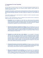
† During a Media Session – This sits somewhere between personal and
terminal mobility and refers to the ability of a user to maintain a session
whilst changing terminals. It is sometimes called service mobility. For
example, User A might want to transfer a call that started on their mobile
phone on to the PC when they reach the office, or they might want to
transfer the video part of a call on to a high-quality projector. The main SIP
technique to achieve such session mobility is to explicitly transfer the
session to the new destination using the REFER request message – see
Figure 5.1. The REFER tells User B to re-INVITE User A at User A’s
address
5
; the call-ID is included so User A knows that this is not a fresh
INVITE. Alternatively, User A could send the REFER to their new terminal,
and it would then send the re-INVITE to User B.
SIP – A PROTOCOL FOR PERSONAL MOBILITY 149
5
This implies that the application must be able to cope with application-layer recovery.
5.4 Introduction to Terminal Mobility
The rest of this chapter considers terminal mobility in an IP network, covering
the ‘IP layer’solutions. This section briefly considers the important distinction
between (terminal) macro- and micromobility. Subsequent sections look at
some specific approaches and protocols for macromobility (in particular
Mobile IP, but also briefly the possible use of SIP for terminal mobility) and
micromobility (in particular, the tunnel-based protocols of hierarchical
mobile IP and fast mobile IP, and the per-host forwarding protocols of cellular
IP, Hawaii and MER-TORA). The chapter then compares the various micro-
mobility protocols. Finally,itlooks at some other featuresthatare important for
a complete terminal mobility solution (paging, context transfer, and security).
The basic job of a terminal mobility protocol is to ensure that packets
continue to be delivered to the mobile terminal, despite its movement result-
ing in it being connected through a different router on to the network. The
main requirements are that the protocol does this:
† Effectively – Including for real time sessions.
† Scalably – For big networks with lots of mobiles.
† Robustly – For example to cope with the loss of messages.
5.4.1 Macromobility vs. Micromobility
It is generally agreed that IP terminal mobility can be broken into two comple-
mentary parts – macromobility and micromobility – and that these need two
different solutions. These terms are generally used informally to mean simply
‘mobility over a large area’ and ‘mobility over a small area’. It might seem a
little strange that such woolly definitions should lead to such firm agreement
that there needs to be two different solutions. In fact, the important distinction
IP MOBILITY150
Figure 5.1 Use of SIP REFER message for application-layer mobility (User A moves on to a new
terminal).
is between terminal mobility to a new administrative domain (AD) and within
the same AD
6
. For example, a mobile might move around a campus wireless
network, handing over from one wireless LAN base station to another, and
then off on to a public mobile network. These handover cases are significantly
different, because an inter-AD handover implies that:
† The mobile host needs to be re-authenticated, because the security/trust
relationship is much weaker between ADs than within one.
† The user’s charging regime, priority, and QoS policy are all likely to be
changed.
† A different IP address must be used (because IP addresses are owned by
the AD), whereas it may or may not be for an intra-AD handover (it
depends on the particular micromobility protocol).
† Issues such as the speed and performance of the handover are less rele-
vant, simply because such handovers will be much rarer.
† There is no guarantee of mobility support in the new AD, because the
protocols being run are not certain, and therefore an inter-AD handover
must rely on protocols that can exist outside the two ADs involved.
It is thus suggested that two complementary protocols are needed: one
solving the macromobility problem and one the micromobility.
However, as will be discussed later, micromobility protocols implicitly
assume mobility within an Access Network (rather than within an Adminis-
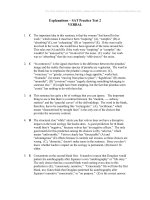
trative Domain). The terminology used is (see also Figure 5.2):
† An Access Network (AN) is simply a network with a number of Access
Routers, Gateway(s) and other routers.
† An Access Router (AR) is the router to which the mobile is connected, i.e.
that at the ‘edge’ of the Access Network. It is an IP base station.
† An Access Network’s Gateway (ANG) is what connects it to the wider
Internet.
† The other Routers could be standard devices or have extra functionality to
support IP micromobility or quality of service.
The Access Network and Administrative Domain may correspond to each
other, but they may not; for example, the operator could design an AN on
technical grounds (e.g. how well does the micromobility protocol scale?),
rather than the commercial focus of the AD (e.g. inter-working agreements
with other operators). This leaves a ‘hole’, i.e. an ‘inter-AN, intra-AD hand-
over’; at present, it seems that a macromobility protocol is fully adequate to
handle this.
Finally, on a terminological point, some people do not like the term
‘micromobility’, basically because it has been used to mean a variety of
slightly different things over the years, and so can cause confusion. Alter-
INTRODUCTION TO TERMINAL MOBILITY 151
6
Being used in the sense [draft-ietf-mobileip-reg-tunnel-03.txt] Domain: A collection of networks
sharing a common network administration.
native terms include intra-access network mobility, localised mobility
management and local mobility. Also, an alternative term for ‘macromobi-
lity’ is global mobility.
5.5 Mobile IP – A Solution for Terminal Macromobility
5.5.1 Outline of Mobile IP
The best-known proposal for handling macromobility handovers is
Mobile IP. Mobile IP has been developed over several years at the
IETF, initially for IPv4 and now for IPv6 as well. Mobile IP is the nearest
thing to an agreed standard in IP-mobility. However, despite being in
existence for many years and being conceived as a short-term solution,
it still has very limited commercial deployment (the reasons for this are
discussed later); Mobile IP products are available from Nextel and ipUn-
plugged, for example.
In Mobile IP, a mobile host is always identified by its home address,
regardless of its current point of attachment to the Internet. Whilst situated
away from its home, a mobile also has another address, called a ‘Care-of
Address’ (CoA), which is associated with the mobile’s current location.
Mobile IP solves the mobility problem by storing a dynamic mapping
between the home IP address, which acts as its permanent identifier, and
the care-of address, which acts as its temporary locator.
The key functional entity in mobile IP is the Home Agent, which is a specia-
lised router that maintains the mapping between a mobile’s home and care-of
addresses. Each time the mobile moves on to a new subnet (typically, this
means it is moved on to a new Access Router), it obtains a new CoA and
registers it with the Home Agent. Mobile IP means that a correspondent host
can always send packets to the mobile: the correspondent addresses them to
the mobile’shomeaddress – so thepackets areroutedto the home link– where
the home agent intercepts them and uses IP-in-IP encapsulation (usually) to
tunnel them to the mobile’s CoA. (In other words, the home agent creates a
IP MOBILITY152
Figure 5.2 Terminology for Access Network.
new packet, with the new header containing the CoA and the new data part
consisting of the complete original packet, i.e. including the original header.)
At the other end of the tunnel, the original packet can be extracted by remov-
ing the outer IP header (which is called decapsulation). (Figure 5.3a and 5.3b).
Note that mobile IP is only concerned with traffic to the mobile – in the
reverse direction, packets are sent directly to the correspondent host, which
is assumed to be at home. (If it is not, mobile IP must be used in that direction
as well.)
A couple of key features of mobile IP are:
† It is transparent to applications. They can continue to use the same IP
address, because the home agent transparently routes them to the mobi-
le’s current care-of address.
† It is transparent to the network. The network’s standard routing protocol
continues to be used. Only the mobiles and the home agent (and foreign
agents – see later) know about the introduction of mobile IP – other routers
are unaffected by it.
On the downside, mobile IP causes transmission and processing overhead.
5.5.2 Mobile IPv4
The Mobile IPv4 protocol is designed to provide mobility support in an IPv4
network. As well as the Home Agent (HA), it introduces another specialised
router, the Foreign Agent (FA). For example, each access router could be a
FA. A mobile node (MN) can tell which FA it is ‘on’ by listening to ‘agent
advertisements’, which are periodically broadcast by each FA. The adver-
tisement includes the FA’s network prefix. When the MN moves, it will not
realise that it has done so until the next time it hears a FA advertisement; it
then sends a registration request message. Alternatively, the MN can ask that
an agent sends its advertisement immediately, instead of waiting for the
periodic advertisement.
Mobile IPv4 comes in two variants, depending on the form of its CoA. In
the first, the MN uses the FA’s address as its CoA and the FA registers this
‘foreign agent care-of address’ (FA-CoA) with the HA. Hence, packets are
tunnelled from the HA to the FA, where the FA decapsulates and forwards the
original packets directly to the MN. In the second variant, the MN obtains a
CoA for itself, e.g. through DHCP, and registers this ‘co-located CoA’ (CCoA)
either directly with the HA or via the FA. Tunnelled packets from the HA are
decapsulated by the MN itself.
The main benefit of the FA-CoA approach is that fewer globally routable
IPv4 addresses are needed, since many MHs can be registered at the same
FA. Since IPv4 addresses are scarce, it is generally preferred. The approach
also removes the overhead of encapsulation over the radio link, although, in
practice, header compression can be used to shrink the header in either the
FA-CoA or CCoA scenario.
MOBILE IP – A SOLUTION FOR TERMINAL MACROMOBILITY 153
There are several problems with Mobile IPv4, which can be alleviated
with varying success. These are discussed below.
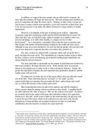
Triangular Routing and Route Optimisation
In the basic Mobile IPv4 described above, all packets from the correspon-
dent node (CN) go via the HA to the MN. This ‘triangular’ route can be very
inefficient – imagine a visitor from Australia to England communicating with
someone in the same office. An optional extension to MIP, called Route
Optimisation allows a CN to send packets directly to a MN. It works by
the HA sending a binding update to the CN, in response to mobile node
warnings or correspondent node requests. (Figure 5.3c). However, route
optimisation does require an update to the CN’s protocol stack (so it can
cache the MN’s CoA and do encapsulation), and it may not be useful in some
circumstances (e.g. if the MN has signed up to many servers that ‘push’
information occasionally).
Reverse Tunnelling
Mobile IPv4 suffers from a practical problem with firewalls (or, more gener-
ally, a router that performs ingress filtering). A MN uses its home address as
its source address, but a firewall expects all packets within its network to use
a topologically correct source address (i.e. to use the same network prefix)
and will therefore throw away packets from the MN. To circumvent this, an
extension has been added, known as Reverse Tunnelling. It establishes a
‘reverse tunnel’, i.e. from the care-of address to the home agent. Sent packets
are then decapsulated at the home agent and delivered to correspondent
nodes with the home address as the IP source address.
NAT Traversal
Similarly, Mobile IPv4 suffers from a practical problem with Network
Address Translators (NATs). NATs are discussed in more detail in Chapter
3. They are used extensively in IPv4 networks, owing to the shortage of
publicly routable IPv4 addresses. They allow many IP nodes ‘behind’ a
NAT to share only a few public addresses, and indeed for several nodes to
share the same address simultaneously, whilst using different port numbers.
The latter is particularly problematic for Mobile IP: the HA (or CN) tunnels
packets, using IP-in-IP encapsulation, to the MN’s publicly routable care-of
address; when the packets reach the NAT, it must translate the address to the
MN’s actual private care-of address – but if several MNs are sharing the same
address, it cannot do this. A proposed solution involves using IP-in-UDP
encapsulation; the UDP header carries the extra information about the
port number, which allows the NAT to identify the correct MN.
IP MOBILITY154
Address shortage
Even when FA-CoAs are used, the MN still needs a home address. The
shortage of IPv4 addresses means that an ISP or network operator would
much rather give each user an address dynamically (through DHCP).
Foreign Agents
The need to deploy FAs has perhaps proved the biggest stumbling block to
the deployment of Mobile IPv4: It is extra kit for a network operator to buy;
the mobile loses service if it moves on to a network without foreign agents;
it makes security harder to implement, because the home agent must trust
the foreign agents; and it is in tension with the end-to-end IP design prin-
ciple, because there is a point in the network that modifies the packet.
5.5.3 Mobile IPv6
Mobile IPv6 is designed to provide mobility support in an IPv6 network. It is
very similar to Mobile IPv4 but takes advantage of various improved features
of IPv6 to alleviate (solve) some of Mobile IPv4’s problems.
† Only CCoAs need to be used, because of the increased number of IPv6
addresses.
† There are no foreign agents. This is enabled by the enhanced features of
IPv6, such as Neighbour Discovery, Address Auto-configuration, and the
ability of any router to send Router Advertisements.
† Route Optimisation is now built in as a fundamental (compulsory) part of
the protocol. Route Optimisation binding updates are sent to CNs by the
MN (rather than by the home agent).
† There is no need for reverse tunnelling. The MN’s home address is carried
in a packet in the Home Address destination option
7
. This allows a MN to
use its care-of address as the Source Address in the IP header of packets it
sends – and so packets pass normally through firewalls.
† Packets are not encapsulated, because the MN’s CoA is carried by the
Routing Header option added on to the original packet
8
. This adds less
overhead costs and possibly simplifies QoS (see later).
† There is no need for separate control packets, because the Destination
Option allows control messages to be piggybacked on to any IPv6 packet.
MOBILE IP – A SOLUTION FOR TERMINAL MACROMOBILITY 155
7
A header option means that the normal IP packet header is extended with an optional field
carrying useful information. See Chapter 3 for more details on header options.
8
In fact, packets sent via the Home Agent, i.e. before Route Optimisation, cannot use the Routing
Header without compromising security, and so the HA must tunnel packets to the MN’s CoA.
IP MOBILITY156
Figure 5.3 Mobile IP. (a) Triangular registration and routing (b) Packet encapsulation (c) Route
optimisation.
5.5.4 Relationship of SIP and Mobile IP
Earlier, the use of the Session Initiation Protocol (SIP) for personal (including
session) mobility was described. However, SIP can also be used for terminal
macromobility. The idea is conceptually very similar to mobile IP.
A mobile node re-registers with its SIP location database each time it
obtains a new IP address – this is just like the binding updates to the home
agent in mobile IP. A correspondent wishing to communicate with the MN
sends a SIP INVITE, which reaches the MN’s SIP server. If this is a SIP proxy
server, it forwards the INVITE to the MN at its current IP address, whereas if it
is a SIP redirect server, it tells the correspondent the MN’s IP address so that it
can ask directly. This is reminiscent of the versions of mobile IP without and
with route optimisation, respectively.
If the MN moves during a call, it can send the correspondent another
INVITE request (with the same call identifier) with the new address (in the
CONTACT field and inside the updated session description). This is very
similar to the session mobility described earlier.
So, is there any difference between SIP and mobile IP for terminal mobi-
lity? Well, whereas mobile IP requires the installation of home agents and
modifications to the mobile’s operating system (and the correspondents if
route optimisation is used), SIP requires the presence of SIP servers and that
the host and correspondent run the SIP protocol
9
. So, in some ways, the
question of whether SIP or mobile IP is better for terminal mobility is really a
judgement about which protocol will turn out to be more successful. Favour-
ing SIP is its wide functionality and its use in the IMS (Internet Multimedia
Subsystem) of UMTS Release 5, whereas Mobile IP’s backers could point to
its longevity and use in 3GPP2, for example.
Of course, it is quite possible to believe that both SIP and mobile IP will
have a role and that actually they will complement each other. There are a
number of ways in which this could happen. For example, SIP could be used
for personal mobility and mobile IP for terminal macromobility, by register-
ing the home address with the SIP server; as variants, the SIP server could use
the home agent as its location register, or the mobile could register its CoA
with the SIP server. Another option is for macromobility to be supported by
mobile IP for long-lived TCP connections (e.g. FTP), and by SIP for real-time
sessions.
MOBILE IP – A SOLUTION FOR TERMINAL MACROMOBILITY 157
9
In fact, the requirement is slightly stronger than this for TCP applications, where the TCP connec-
tion needs to be maintained during a move. One possible solution is that a mobile uses a TCP
tracking agent (SIP-EYE) to maintain a record of ongoing TCP connections, and when it hands
over, it sends a SIP INFO message to the correspondent asking for the mobile’s old address to be
bound to its new address. This is very reminiscent of route-optimised mobile IP with co-located care-
of addresses.
5.6 Terminal Micromobility
5.6.1 Introduction
This is quite a long section, and the reader is encouraged to skip between
areas of particular interest. One reading route is to tackle the introduction
sections (this one, plus the introductions to local mobility agent schemes, fast
and smooth mobile IP schemes, and per-host forwarding protocols), perhaps
followed by the comparison section or the specifics of a particular protocol.
The obvious way to provide (terminal) micromobility is simply to use
mobile IP. However, this presents a number of problems
10
, some of which
are:
† Handovers may be slow, because the mobile must signal its change of
care-of address (CoA) to the home agent. This may take a long time if the
home agent is far away, perhaps in a different country.
† The messaging overhead may be significant, particularly if the home agent
is distant, as this will induce signalling load in the core of the Internet.
† Mobile IP may interact with quality of service (QoS) protocols, thus
making QoS implementation problematic. For example, mobile IP utilises
tunnels, and so packet headers – which may contain QoS information –
become invisible.
Instead, researchers suggest that a more specialised protocol is needed to
deal with micromobility. We will assume in the discussion below that the
packets ‘somehow’ have been delivered to an access network’s (AN’s) gate-
way, or else that they have originated within the AN (i.e. a mobile to mobile
call).
There has been a huge amount of work on the micromobility problem,
with many different ideas and protocols suggested.
Broadly speaking, there are two ways of dealing with micromobility:
† Mobile IP-based schemes – these extend basic mobile IP. They are char-
acterised by the use of tunnelling (and Router headers in IPv6), and in
general by the mobile acquiring a new care-of address (CoA) each time it
moves.
† Per-host forwarding – these introduce a dynamic Layer 3 routing protocol
in the AN. In general, the mobile keeps its CoA whilst it remains in the AN.
There are two common aims to improve on basic mobile IP:
† To reduce the signalling load by localising the path update messages to
within the AN or some part of it. This is done by introducing mobility
IP MOBILITY158
10
Using SIP for micromobility would raise similar problems. Note also that the operator may not
want to be driven by mobility considerations when positioning SIP servers and SIP location databases
in the network.
functionality on one, or some, or all of the routers in the access network so
that the Home Agent can remain unaware that the MH has moved.
† To speed up handovers, so, from a mobile’s point of view, its application
does not see a significant delay and suffers no loss of packets. Such hand-
overs are, respectively, said to be ‘fast’ and ‘smooth’, or ‘seamless’ if both
apply.
Mobile IP-based schemes
Two complementary threads of work have been taking place.
Local Mobility Agents
These have been developed on the basis that mobile IP is almost the right
way of doing it. They assume that mobile IP’s problems arise only from the
potentially long distance signalling back to the home agent when a mobile
moves, which can be solved by introducing a local proxy mobility agent. In
this way, when the mobile changes its CoA, the registration request (usually)
does not have to travel up to the home agent but remains ‘regionalised’.
These schemes are predominantly concerned with reducing the signalling
load, compared with basic mobile IP.
‘Fast and Smooth’ Mobile IP-based Schemes
This refers to a variety of ‘tricks’ introduced to try to make the mobile IP
handover seamless (reduction of signalling is not particularly a concern). The
most important idea is to use supplementary information to work out that a
handover is probably imminent (for instance, this could be link layer power
measurements) and to take proactive action on the mobile’s behalf. The main
steps are to acquire a new CoA that the mobile can use as soon as it moves
on to the new access router (AR), and to build a temporary tunnel between
the old and new ARs, which stops any packets being lost whilst the binding
update messages are being sent.
Per-host Forwarding Schemes
In per-host schemes, the information about the location of the mobiles is
spread across several of the routers in the access network. In terms of the
earlier discussion, the mapping between a mobile’s identifier and its locator
is distributed rather than centralised. The location information simply indi-
cates the next router to forward a packet on to, rather than its final destina-
tion. Compared with basic mobile IP, these schemes are generally concerned
with both reducing the signalling load and speeding up handovers.
Three broad techniques for per-host forwarding have been explored:
TERMINAL MICROMOBILITY 159
New Schemes
These schemes assume that it is best to design a new, dynamic Layer 3
routing protocol to operate in the AN. The new protocol installs forwarding
entries for each Mobile Host (MH) within the Access Network. The well-
known Cellular IP and HAWAII (Handoff-Aware Wireless Access Internet
Infrastructure) protocols fall into this category.
MANET-based Schemes
MANET protocols were originally designed for Mobile Ad hoc NETworks,
where both hosts and routers are mobile, i.e. there is no fixed infrastructure
and the network’s topology changes often. Clearly, therefore, a MANET
protocol can cope with our scenario, where there is a fixed infrastructure,
and only hosts can be mobile, although one would expect some modifica-
tions to optimise the protocol.
Multicast-based Schemes
The claim here is that the mobility problem is rather like the multicast
problem, in that in neither case is a terminal in a fixed, known place.
The basic idea is that the protocol builds a multicast ‘cloud’ centred on
the MH’s current location but which may also cover where it is about to
move to.
Typically, per-host forwarding schemes have the following characteristics:
† The way in which IP addresses are assigned is unrelated to the mobile’s
current position within the network topology
11
. This is substantially differ-
ent from IP address assignment in the normal Internet.
† There is no encapsulation or decapsulation of packets. Amongst other
things, this avoids the overhead associated with mobile IP-based
schemes.
† Signalling is introduced to update the mobile specific routes, which is
interpreted by several routers within the access network (whereas signal-
ling in mobile IP-based protocols is transmitted transparently by the AN’s
routers between the mobiles and the mobility agents).
Figure 5.4 shows a family tree for some IP mobility protocols. The refer-
ences provide further details on the various protocols discussed.
5.6.2 Mobile IP-based Protocols
Local Mobility Agent Schemes
These protocols introduce a local mobility agent, which is just a specia-
IP MOBILITY160
11
As will be seen later, this does not apply to all per-host forwarding schemes.
lised router that essentially acts as a local proxy for the home agent. When a
mobile moves, it normally hands over between two access routers that are
‘under’ the same local mobility agent. Hence, it only needs to inform this
mobility agent; the Home Agent and correspondent hosts remain unaware of
the move. There are two things this should achieve:
† Reduce the amount of signalling – there are fewer messages (just one local
update, rather than one to the home agent and – assuming route optimi-
sation – one to each correspondent) and also a shorter distance for the
messages to travel.
† Reduce the latency associated with a handover – because the update only
has to travel as far as the local mobility agent. So, the users will see a
shorter break in their communications.
The basic method is that as well as the standard home address and care-of
address, the mobile has an extra care-of address (CoA) that is associated with
the local mobility agent. The home agent remembers which local mobility
agent the mobile is on, whereas the local mobility agent can tunnel packets
on towards the correct AR. A correspondent host sends its packet either to
the home agent or to the local mobility agent after route optimisation. There
is no attempt to route-optimise further, i.e. to the CoA associated with the
current AR, since this would involve extra signalling and degrade (at least
part of) the advantage of the local mobility agent.
TERMINAL MICROMOBILITY 161
Figure 5.4 Protocol family tree for IP mobility (underlined protocols are discussed in this Chapter).
It is also suggested that there can be a hierarchy of local mobility agents, so
that packets would be sequentially tunnelled from one to the next. However,
this is generally opposed, owing to the processing delays involved in repeat-
edly de-/re-tunnelling, and also robustness issues (see later).
Much prior work has now been merged into two Internet Drafts, one for
mobile IPv4 and one for v6, which are now discussed.
Regional Registration for Mobile IPv4
Regional registration introduces a Gateway Foreign Agent and optionally
Regional Foreign Agents as level(s) of hierarchy below the GFA. The mobile
can use either a co-located or foreign agent care-of address (i.e. as normal).
This is called the ‘local CoA’ and is registered with the GFA (or RFA, if
present), whereas the GFA’s address is registered with the home agent as
the mobile’s CoA.
The foreign agent includes the ‘I’ flag
12
in its advertisement, to indicate
that regional registration is operating in the access network. The advert
announces the GFA’s address as well as the FA’s address (or its NAI).
Two new message types are introduced: the regional registration request
and regional registration reply. These are just like the normal MIPv4 registra-
tion request and reply, but are used for registration with the GFA
13
.
Home Registration
When the mobile changes GFA or arrives in a new access network, it
performs a ‘Home Registration’. This involves sending a MIPv4 Registration
Request to the GFA
14
, with the care-of address field equal to the GFA
address
15
, and with the mobile’s CoA included in the Hierarchical Foreign
Agent extension. The GFA updates its visitor list and then sends the registra-
tion request on to the home agent.
Regional Registration Request
When the mobile moves to a new FA but is still on the same GFA, it
performs a ‘Regional Registration’. This involves sending a Regional Regis-
tration Request to the GFA, informing the GFA of its new ‘local CoA’; the
GFA does not inform the home agent. If RFAs are being used, there is one
extra complication, which is that it is possible for the tunnels to become
IP MOBILITY162
12
A flag is a particular bit in the header that the protocol defines to have a particular meaning.
13
It is almost possible simply to use the normal MIPv4 registration request and reply, but unfortu-
nately, there are a coupled of detailed optional cases where it would not be possible to distinguish
between whether a regional or normal registration was intended.
14
If the MH has a CCOA, it can send the registration directly to the GFA. However, if it has a FA-
COA, the registration must be relayed via the FA.
15
An option is to set the CoA field to zero, in which case, the mobile is assigned a GFA.
incorrectly directed if a mobile moves back to a previous FA. The solution
is to explicitly de-register the old entries by sending a binding update with a
zero lifetime to the mobile’s previous CoA.
Thus, after the initial home registration with the home agent, subsequent
mobile registrations can be localised within the access network.
Hierarchical Mobile IPv6
This is very similar to regional registration, and most of the differences are
terminological – for example, the local mobility agent is called the Mobility
Anchor Point (MAP). There are in fact two modes.
In ‘basic mode’ hierarchical mobile IP, a mobile obtains its CoA (called a
Regional CoA, RCoA), through standard stateless address autoconfiguration
(i.e. it consists of the MAP’s subnet prefix plus the mobile’s interface identi-
fier). This is a globally routable address that the home agent (and correspon-
dents, after route optimisation) routes to; in other words, the RCoA routes
packets as far as the mobile’s MAP. In order to route packets the rest of the
way, each time the mobile moves, it sends the MAP a binding update with its
new ‘on-link’ care-of address, LCoA. The message is just a regular mobile
IPv6 binding update with an extension, the M flag, to distinguish it from a
regular home registration or route optimisation message.
Mobiles need to discover nearby MAP(s). One method is for the MAP to
send out a MAP router advertisement (which is a regular IPv6 router adver-
tisement, with an extension containing the MAP’s global address). This
propagates through the access network until it reaches the access routers,
which transmit it over the air. Hence, a mobile can listen to the advertise-
ments and work out when it has moved into a new MAP’s area; the mobile
can then obtain a new RCoA and send regular mobile IPv6 binding update(s)
to its home agent and correspondent(s). Further extensions can indicate the
MAP’s ‘preference’ (so an overloaded MAP could lower its preference rating,
for instance), and the number of hops to the MAP. The last feature might let a
mobile choose a distant MAP if it is moving extremely fast, to reduce the
frequency of inter-MAP updates, and a nearby MAP if it is communicating
with a local correspondent as suggested in Figure 5.5.
The other mode of hierarchical mobile IP is called ‘extended mode’. This
deals with the scenario where there are mobile routers, i.e. a mobile that has
further mobile hosts attached to it – for example a Personal Area Network.
The idea is that the mobile router acts as a MAP; the mobile hosts therefore
use the mobile router’s RCoA as their CoA, called the alternate CoA
16
. This is
like the Foreign Agent variant of mobile IPv4.
TERMINAL MICROMOBILITY 163
16
Trying to run basic mode in this mobile router scenario is fraught with difficulties. For example, if
the mobile hosts obtain their own RCoA from the mobile router (i.e. their MAP is at the mobile router),
then every time the mobile router moves, it has to obtain a new network prefix, and the mobile hosts
have toobtaina new CoA. By contrast, if the mobile hosts obtain their RCoAs from a MAP further in the
network, then after the mobile router has moved, their RCoAs will no longer be globally routable.
‘Fast and Smooth’ Mobile IP-based Schemes
Mobile IP, as described above, can suffer from a break in communications
during a handover. This section will outline ways specifically targeted at
making the handover smoother (i.e. packets are not lost) and faster (i.e. pack-
ets reach the mobile with a smaller delay). Unlike the local mobility techni-
ques above, these are not concerned with reducing the signalling load.
The basic approaches that can be employed are described below.
IP MOBILITY164
Figure 5.5 Hierarchical mobile IPv6. A mobile node selects a different MAP for correspondent
nodes #1 and #2, as shown in (a) and (b) respectively.
Two CoAs
This is actually a feature of Mobile IP, and applies if the mobile is capable of
listening on two links at once (i.e. make before break). Providing a mobile is
allowed to hold on to its old CoA for a short period of time after the handover,
it can accept packets arriving at the old or new link. This means that when a
mobile hands over, packets that are sent before the binding update reaches
the home agent (i.e. to the old CoA) will still reach the mobile and be
accepted by it.
The new ‘fast mobile IP’ schemes (sort of) extend this idea to break before
make handovers. A mobile can configure its new CoA whilst still attached to
the old access router – this speeds up the registration process when the
mobile moves on to the new access router.
Simultaneous Bindings and Packet Bi-casting
This is an optional feature in Mobile IPv4. A mobile sets the ‘S’ flag in its
registration request, and the home agent interprets this as a request to retain
the previous mobility binding(s), as well as adding the new binding (hence
‘S’ for simultaneous bindings). Subsequent packets from a correspondent can
then be duplicated (‘bi-casted’) by the home agent, with a copy sent to each
CoA.
This idea has been extended by performing the duplication locally (e.g. at
the foreign agent). Additionally, it has been proposed to buffer packets
locally during a handover.
Temporary Tunnel
This is another optional feature of Mobile IP that ‘fast mobile IP’ schemes
propose extending. The basic idea is to establish a temporary tunnel from the
previous CoA to the new CoA. Hence, packets coming from correspondent
nodes that have not yet been told the new CoA (or indeed packets in flight
from the home agent) will be forwarded on to the mobile. In Mobile IPv6, the
method is that, whilst at its old point of attachment, the mobile discovers
(from router advertisements) a ‘local’ router that has the capability to act as a
home agent (typically just the old access router). Now, when the mobile
connects to the new link and receives its new CoA, it sends a binding update
to this router with a special field set (the home registration bit), which asks
the router to act as a temporary home agent – it can then intercept packets
addressed to the old CoA and tunnel them on to the mobile at its new CoA.
The same idea is seen in Mobile IPv4’s Route Optimisation extension. The
mobile adds the Previous Foreign Agent Notification extension to its binding
update, which causes the new FA to send a binding update to the previous
FA, which sets up a tunnel between the previous FA and the new CoA. (A FA
TERMINAL MICROMOBILITY 165
indicates that it can support such forwarding by setting the ‘S’ flag in its agent
advertisement. Here, ‘S’ is for smooth handovers.).
We see below that the method has been extended for the case where the
tunnel can be set up in advance of the actual handover.
‘Fast mobile IP’ schemes are under intensive development in the IETF’s
mobile-IP working group. Many protocols have been proposed, but work is
now converging into one protocol for IPv4 and one for IPv6. A few details are
now outlined, although some are liable to have changed by now.
Fast Handovers for Mobile IPv6
The main idea of this protocol is that it is often known what the next Access
Router is likely to be before the mobile actually hands over on to it. This ‘hint’
could, for example, come from power or signal-to-noise ratio measurements,
or from knowledge of a mobile’s likely movements (e.g. if it is on a train).
Hence, some proactive action can be taken in advance of the actual handover
– if desired, the handover can be initiated before theMN has connectivity with
the new AR. Overall, this should mean that from the point of view of ongoing
communications between the mobile and its correspondents, the handover is
apparently smoother and faster. This type of approach is familiar from current
cellular networks, where the mobile reports on the signal strength from nearby
base stations, thus allowing the network to plan for handovers.
The basic ideas are to:
† Enable the mobile node to configure a new CoA before it moves on to the
new AR, so that it can use the new CoA as soon as it connects with the
new AR. This eliminates the delay seen in mobile IP from the registration
process, which can only begin after the Layer 2 handover to the new AR is
complete. There is an implicit assumption that the mobile is only capable
of connecting with one AR at a time, i.e. break before make, otherwise the
mobile IP feature above (two CoAs) can be used.
† Ensure that no packets are lost during the handover by establishing a
temporary tunnel from the old to the new AR. The technique is basically
an extension of the MIP feature above (point 3) to the case of a planned
handover.
Figure 5.6 shows the basic messages involved.
Fast Handovers for Mobile IPv4
Fast handovers (or ‘low latency handoffs’ in their terminology) have also
been considered for mobile IPv4. At present, there are several differences
from fast mobile IPv6, and in fact, fast mobile IPv4 currently includes two
different techniques called pre- and post-registration. Fast mobile IPv4 and
v6 might be expected to converge on the same basic approach.
The ‘pre-registration’ method has the same idea as fast mobile IPv6 above,
IP MOBILITY166
in that a proxy router advertisement from the old foreign agent is used to
inform the mobile node about the prospective new foreign agent. There are
several slight differences, which mainly stem from using a normal registration
request/reply (i.e. there are not special ‘fast’ messages).
The ‘post-registration’ method is slightly different. It is more like normal
mobile IP, in that no attempt is made to register the mobile node with the
new FA until after the mobile has a Layer 2 link established with it. Instead,
some sort of Layer 2 trigger causes the network to set up a ‘bi-directional
edge tunnel’ (BET) between the old and new FAs. The old FA bicasts packets
to the new FA down the tunnel, so that when the mobile node makes a Layer
2 connection with the new FA, it immediately obtains its downlink packets. It
can also send packets immediately – still using its old care-of address as the
source address – because the new FA tunnels them to the old FA, where the
packets are de-capsulated and forwarded; if the tunnel were not in place, the
new FA might filter the packets because the source address was suspicious.
Meanwhile, the mobile can, at its leisure, use standard mobile IP to register
the new CoA; subsequently, it will of course need to tell the old FA to stop
bicasting and to tear down the tunnel.
TERMINAL MICROMOBILITY 167
Figure 5.6 Fast mobile IPv6 handover. (a) Handover preparation phase of mobile-controlled
scenario (b) Handover execution phase of mobile-controlled scenario.