Tài liệu Dịch vụ mạng thế hệ kế tiếp P1 doc
Bạn đang xem bản rút gọn của tài liệu. Xem và tải ngay bản đầy đủ của tài liệu tại đây (222.09 KB, 15 trang )
1
Circuit Switched
Technologies
1.1 THE EVOLUTION OF CIRCUIT SWITCHING
The current circuit switched network concept has remained essentially
unchanged from the original electromechanical Strowger exchange (see
the Preface for an explanation of how this exchange came by its name). At
its most basic level the telephone network comprises transmission paths
and switching nodes.
The design of a circuit switch is based on the ability to physically create
a path (circuit) from one network element to another and to hold this path
open for the duration of the interaction (call). The second role of circuit
switching is routing, i.e. determining the path to take from the ingress
point to the egress point in the network. This can be performed in multi-
ple stages, each switching stage being linked by transmission paths. In the
Strowger exchange routing was performed on a step-by-step basis, using
the pulsed make and break signalling from the telephone dial to step
electromechanical selectors.
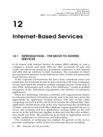
Figure 1.1 depicts a simple scenario of an own-exchange call (i.e. a call
that only involves one routing and switching stage). This is similar to
what would have occurred in the second exchange opened in the UK.
Called the ‘official switch’, it was used as a private branch exchange by post
office officials at the post office HQ. It can be clearly seen from this simple
example how routing is taking place in a step-wise fashion and a physical
path is being created at the same time. Clearly, a more complex routing
mechanism is required for national and international calls, this is
performed by multiple stages of switching and routing connected via
transmission paths. In this way the hierarchical nature of the routing
Next Generation Network Services
Neill Wilkinson
Copyright q 2002 John Wiley & Sons, Ltd
ISBNs: 0-471-48667-1 (Hardback); 0-470-84603-8 (Electronic)
and thus numbering plan, local, transit and international evolved. It is on
this basis the worldwide numbering scheme evolved!
This example also demonstrates the physical dimensions a Strowger
exchange occupied, each electromechanical selector was housed with a
number of others in a metal rack. Each of these racks was placed in
exchange buildings, in equipment halls. It is safe to say that nearly all
Strowger exchanges have now been replaced by electronic exchanges,
1
their replacements being significantly smaller, with greatly increased
functionality.
BT crossbar switches (TXK) replaced a number of the Strowger
exchanges in the UK. This was a major change, and out went the unise-
lectors, two-way selectors and progressive control (each switching stage
having its own control equipment), to be replaced by a common control
and a cross point switch block. Whilst this common control function could
only handle one call at a time, its operations were faster than the Strowger
staged approach and so a seemingly simultaneous operation could be
achieved. A similar evolution occurred in other parts of the world as
switch manufacturers released newer switches.
CIRCUIT SWITCHED TECHNOLOGIES4
Figure 1.1 Strowger routing scheme –10,000-line, four-digit numbering
1
The last Strowger exchange was removed in the UK in 1995, if any do remain, they are in
developing countries.
In the UK, electronic switching finally usurped the crossbar design in
the 1960s with the TXE2 exchange, which used discrete semiconductors in
the common control equipment and reed relays in the switch matrix.
TXE4 and 4A came along in the 1970s. TXE4A used large-scale integrated
circuits in the common control block. This was still in essence a mechan-
ical exchange, with a metallic path from end to end (the TXE4s in the UK
network finally disappeared in 1998). It was not until the early 1980s that
the replacement of these exchanges with full digital (TXD) equipment,
with high-speed semiconductor switch matrices and Stored Program
Controllers (SPCs) running software (System X, DMS, AXE10, etc.),
2
finally replaced their mechanical cousins.
3
It was the SPC and semiconductor switch matrix, which brought about
the digitisation of the telephone network. The SPC software could not
only perform basic routing capability (which is what it initially
performed), but also interpret more complex services. It is instructive to
note that this evolution (from the end of Strowger to digital exchanges)
occurred over a relatively short period (30 years).
The common elements of a digital circuit switch are shown in Figure
1.2. The elements are SPC, switch matrix, trunk peripherals and Tones &
Recorded Announcements (T&RA).
The SPC is the brains of the switch where all the programs that control
the call state (finite state machine) reside, along with the signalling, rout-
ing, maintenance, charging, and switch matrix control programs.
The switch matrix comes in a number of forms (each switch manufac-
turer choosing their favourite variation), all of them combine time (also
called channel switching) and space switching. Time switching describes
how timeslots from an incoming time division stream (see Chapter 2 for a
description of timeslots and time division multiplexing) are disassembled
from the incoming stream and reassembled on the outgoing stream. This
is how ‘switching’ takes place. (I will explore switching in a little more
detail in a moment, as this is quite a tricky topic!)
The role of trunk peripherals is to terminate the incoming and outgoing
time division multiplexed streams. Their role is also to ensure that the
streams do not get out of synchronisation, as this would be extremely
detrimental (imagine if the timeslots were out of phase, the control soft-
ware would be connecting the incorrect conversations together!). Timing
for the whole of the switch is also derived from information gained from
the trunk peripherals. Another component is the Tones and Recorded
Announcments (T&RA) source. This component is responsible for
1.1 THE EVOLUTION OF CIRCUIT SWITCHING
2
All trademarks acknowledged.
3
The terminology TXE stands for telephone exchange electronic and along with TXS
(telephone exchange Strowger), TXK (telephone exchange crossbar) and finally TXD
(telephone exchange digital) formed the generic naming of telephone exchange equipment
used in the BT network.
5
generating call progress tones and announcements that are used to
communicate to the caller the status and progress of their call.
Digital switching is performed with two functions: a time switch (see
above) and a space switch also known as a timeslot interchanger. In order
to understand switching a basic knowledge of the transmission framing in
Time Division Multiplex (TDM) is necessary. If you are not familiar with
this, then I suggest you turn to Chapter 2 on the transmission infrastruc-
ture.
To explain time switching, consider Figure 1.3. A bi-directional path is
desired between timeslot 3 on the inbound port and timeslot 27 on the
outbound port. We have already established the fact that the trunk
peripherals look after synchronisation, so if a switch has all its systems
synchronised, then all time division multiplexed streams of voice will be
aligned. A time delay must be introduced between the two time division
multiplexed streams to allow different parts of each stream to overlap (see
Figure 1.3).
CIRCUIT SWITCHED TECHNOLOGIES6
Figure 1.2 Elements of a digital switch
Looking at the figure from left to right, in order for timeslot 3 of the
incoming stream to line up with timeslot 27 of the outgoing stream, a
delay of 24 timeslots is introduced. From right to left, since the 32-timeslot
system repeats frames every 32 timeslots (on a 2.048 Mpbs stream, see
Chapter 3 on transmission infrastructure), then a delay of eight timeslots
from timeslot 27 is timeslot 3 in the next frame. This process is normally
accomplished by the use of Random Access Memory (RAM) to store the
bit pattern from each frame and a counter to index the location in the
memory.
Two digitally encoded voice conversations can be connected to each
other in this way, how do we achieve the connection of hundreds of
thousands of connections in an any-to-any way? This is achieved by the
use of a space switching stage.
Space switching, is as the name suggests, the act of physical displace-
ment of timeslots (Figure 1.4). Consider a number of time switches
aligned on either side of a component that contains a number of crossover
points. In order for a timeslot from one time switch to connect to another
timeslot in another time switch, a cross point in the component (the space
switch) would need to be active at just the right time. The space switch is a
timeshared matrix allowing access to all terminations.
A speech sample arriving in a timeslot on the ingress stream is held in a
receive store. When the time interval allocated to the cross point being
active occurs, the speech sample is read out of the store. The sample
traverses the space switch and is written into a transmission (TX) store.
When the time for the speech sample to be passed on to the egress stream
arrives, it is read from the transmit store.
The final configuration results in a time–space–time architecture (a
space–time–space architecture is also possible). At each space switch
time allocation slot, the data are read from the input time switch store
and transferred across a physical path to an outbound time switch store.
This outbound time switch then reads out the data in the appropriate
1.1 THE EVOLUTION OF CIRCUIT SWITCHING
Figure 1.3 Time switch operation
7
(delayed) outbound timeslot. As you can see this introduces delay at each
switching stage.
Thankfully, not very much delay is introduced. A single frame on a
2048 kbps 32-timeslot bearer takes only 125 ms to transmit. Thus, the
worst-case delay of a whole frame is only 125 ms. However, if this occurs
at every switching stage this delay can soon add up on international links.
Switching is just one component of the connection of telephone calls
across a circuit switched network. Whilst digital switching was a very
important step in enabling the digitisation of the voice network that has
been the enabler for the move to voice and data convergence, the one
invariant throughout the history of circuit switching has been routing.
Routing is the process of interpreting the digits dialled by one customer
into the physical endpoint in the network of the customer they wish to
reach and is performed by software running in the SPC of modern circuit
switches. Routing is based on a hierarchical routing scheme embodied in
the numbering plan. A numbering plan describes the structure for the
organisation of the digits customers/subscribers dial to reach other
subscribers.
Most people are familiar with the hierarchical routing scheme embo-
died in the international numbering plan referred to as E.164. The Inter-
national Telecommunications Union telecommunications (ITU-T)
standard specifies a maximum of 15 digits and a geographic hierarchy
for the international public telecommunications numbering plan. This
numbering plan consists of an international country prefix, followed by
a regional number prefix and finally a local number. This hierarchy allows
CIRCUIT SWITCHED TECHNOLOGIES8
Figure 1.4 Space switch operation
for shortcuts to take place. To call a neighbour, you only need dial the local
number without any prefix digits.
The telephone network is divided into local exchanges (incorporating
concentration stages that concentrate access network traffic on to links to
the local exchange, aka class 5 in the US), transit (or trunk or tandem aka
class 4 in the US) exchanges and international exchanges, reflecting this
hierarchy of routing. This basic infrastructure remained relatively
unchanged all the way up to the 1980s. When the desire to increase the
number of services that, the network could offer, whilst reducing the need
for increasingly complex software on the SPC was achieved. This was
realised by the introduction of the intelligent network architecture (see
Chapter 3).
So routing is the process of interpreting the digits from this call plan
into a meaningful path through the circuit switched network. Routing is a
distributed stage-by-stage process in telephony, with switches at different
levels in the hierarchy taking responsibility for different stages in the
routing.
By way of an example, consider the number 44-1189-428025. This
number has been artificially partitioned into international country code
(44), followed by national prefix (1189) and finally the local digits
(428025). If a subscriber chose to dial from another country (other than
the UK, 44 being the UK country code) then the whole number would be
required in order for the telephone network to route the call. If a caller
based in Reading (UK) wanted to reach the customer whose number was
428025, then they need only dial this shorter digit string. This is because in
the latter case the local exchange that both customers/subscribers are
connected to contains sufficient information in the program in the SPC
to determine the equipment (and thus subscriber’s line) that the number
relates to.
If the caller was outside the area they would call 01189 428025 (in the
UK). The local exchange that the caller is connected to would have to pass
the number up to a transit exchange. The transit exchange could then
determine if it needed to pass the call on to another transit exchange, or
if it had the local exchange that the number related to directly connected
to it. The transit would then pass on the digits to the next exchange in the
hierarchy. In order for exchanges to communicate in this way a mechan-
ism for passing the information between exchanges and signalling
responses back about the results is needed. This is the topic of the next
section.
One final note, the hierarchical approach to routing has been driven by
cost as much as numbering plans. The cost of trunking large volumes of
copper wire and hence subscriber lines over long distances is significant.
The twisted copper pair in most homes is aggregated by local exchange
switching centres and carried over multiplexed co-axial and fibre links to
the tandem exchanges. We will discover (in Chapter 5) that packet-based
1.1 THE EVOLUTION OF CIRCUIT SWITCHING 9
voice networks allow us to flatten this infrastructure in a cost-effective
way.
1.2 SIGNALLING – COMMUNICATING BETWEEN
SWITCHING POINTS
Signalling is the term used to describe the messages that are interchanged
between the switching points in order to facilitate the communication of
what is known as call progress information. What this statement means is
that a mechanism must be in place that allows the communication
between telephone exchanges (which are computers in the case of modern
digital exchanges) of the dialled digits that a customer dials to reach
another customer and a means for errors to be communicated back to
the instigating switch (or even customer).
In keeping with the evolution of switching components, the signalling
and transmission components have also followed an evolutionary path
both at the network edge and in the core of the network.
The edge of the network has slowly undergone the replacement of the
loop-signalling interface to a dual tone signalling method (DTMF also
known as MF4). Loop signalling is, as the name suggests, a means of
signalling the digits dialled by making and breaking a loop circuit between
the telephone handset and the local exchange, the loop being formed using
the copper twisted pair cable connecting the telephone handset with the
telephone exchange. Dual tone multifrequency (DTMF) or multifrequency
signalling number 4, as it is also known, is a mechanism that utilises a
collection of audible tones arranged in pairs associated with each button
on the key pad of a modern telephone handset.
The introduction of digital access signalling at the edge of the network
has occurred in the form of a number of different protocols namely:
† Digital Access Signalling System (DASS 1 and 2), a UK centric proto-
col designed by BT and now largely superseded by DSS1.
† Digital Private Network Signalling System (DPNSS).
† Q.931/I.451 (more accurately known as DSS1 the other two are the
call control protocol standards), used for integrated services digital
network (ISDN) call set-up signalling for basic and primary rate
connections between customer premise equipment and local
exchanges. This is also largely being replaced in Europe by Euro
ISDN a standard developed by Europe Telecommunications Stan-
dards Institute (ETSI).
† Q.SIG, an amalgamation of Q.931 and DPNSS capabilities for signal-
ling for basic and primary rate connections between customer
premise equipment and local exchanges and the construction of
private networks.
CIRCUIT SWITCHED TECHNOLOGIES10
† The US has Telcordia specified ISDN 1 and 2 protocols and Japan has
INS-Net defined by NTT.
† V5, a protocol designed for the connection of concentrator switches to
local exchanges. It has two versions (V5.1 and V5.2), the second
version having more features.
These protocols have allowed the introduction of more sophisticated
devices at the edge of the network and through this the evolution of more
complex services including circuit switched data services (see Chapter 6).
We will not cover these protocols in any more detail, suffice to say they all
provide a similar service. That of connecting digital/electronic equipment
such as Private Branch Exchanges (PBXs) and Automatic Call Distributors
(ACDs) to the public switched telephone network and other private
networks. The key point about the move from analogue signalling at
the edge of the network to digital signalling is the increase in services
and facilities that can be supported, and for example the ability for end
devices to communicate with each other, using the public switched tele-
phone network as a packet data network for carrying those messages.
One facility that makes good use of this is route optimisation. When
two private exchanges (PBXs) are connected together through a number
of other exchanges (as transiting exchanges). One of the parties in the call
wants to redirect their end of the call to a third person and hang up
(transfer the call). The route the new call takes can be optimised by drop-
ping the path of the call back through a number of the intermediate
exchanges until it passes through the minimum number of exchange
links. This facility is provided by signalling messages that pass between
the edge PBXs and intermediate nodes to establish the new route.
The core network signalling, in concert with the access network signal-
ling, has evolved from analogue-based signalling in the form of:
† Loop disconnect (see above) this is a form of direct current signalling
that is only effective over circuits up to about 2 km.
† E&M, stands for ear and mouth signalling, this is a two-way signal-
ling mechanism, ear being the receive signalling and mouth the trans-
mit signalling.
† DC2 and DC3, use current pulses to signal digits and trunk seizures
between exchanges.
† AC8, AC9, AC11 and AC12, these are all what are referred to as out-
of-band and in-band signalling systems. They use frequencies of
sound outside those normally permitted for voice (artificially filtered)
and sounds inside the voice range.
† MF2, like its cousin MF4 (see above), was used for speeding up the
transmission of decadic digits between trunk exchanges by encoding
the digits as a set of in-band tones.
† R1 and R2. Signalling systems R1 (North America) and R2 (Europe)
are used for inter-register signalling. Inter-register signalling
1.2 SIGNALLING – COMMUNICATING BETWEEN SWITCHING POINTS 11
(between trunk exchanges) uses MF in-band pulse signalling at
frequencies of 700–1700 Hz, in 200 Hz steps, for the transmission of
address information. Line signalling is performed in TDM systems as
a set of bits (normally in channel 16 of a 32-channel system and using
bit robbing in US 24-channel systems – see Section 2.2).
To a digital packet-based signalling system called signalling system
number 7 (SS#7). I can hear what you are thinking, ‘‘What happened to
the other SS#x?’’ SS#4, 5, 6 are international analogue signalling systems
specified by the then CCITT (ITU) in the early 1960s. I will not cover any
of the analogue signalling systems in this text because, whilst their impor-
tance is recognised, they are largely being/have been replaced by packet-
based digital signalling in the form of SS#7 in the Public Switched Tele-
phone Network (PSTN).
4
The move over to packet-based systems is
because of a number of reasons. In the previous (analogue) signalling
systems mentioned:
† a direct relationship exists between the telephony traffic route and the
signalling (in packet-based signalling the messages can follow inde-
pendent paths to the telephony traffic);
† only telephony data could be signalled (in packet-based signalling,
network management messages, statistics information and fault
reports are all carried over the signalling system);
† the number of messages are limited;
† the signalling transfer of messages is slow; and
† equipment is inefficiently used because it was generally dedicated to
a specific route.
This brings us neatly on to the now universally accepted packet-based
signalling system, SS#7.
Overview of Signalling System Number 7 (SS#7)
This section covers the signalling protocols set out in the ITU-T
5
standar-
disation sector specifications known as the Q.700 through to Q.775 series
of recommendations. The term recommendation is an interesting one in
that it implies they are not compulsory, however, without almost univer-
sal adoption by telecoms equipment manufacturers and network opera-
tors nothing in the telephone network would work, and would not have
moved beyond operator-connected calls.
CIRCUIT SWITCHED TECHNOLOGIES12
4
I’m certain to get remarks over this point, as I’m sure a significant amount of interna-
tional analogue signalling still exists! The important point is the move to digital signalling
and what that enables.
5
Formally known as the Consultative Committee International, for Telephony & Tele-
graphy (CCITT), the conversion took place on 1 March 1993.
The ITU-T recommendations have peer specifications from the Amer-
ican National Standards Institute (ANSI) and Bellcore (now Telcordia
Technologies) for the North American variants of SS#7, also regional
variants exist, for example Japan, and in the UK, the Telephony User
Part (TUP) protocol is known as IUP and formally as BTUP. A good
reference for a more detailed study of these specifications and SS#7 in
general can be found in [RUSS]. By completing this section, you will be
rewarded with a good foundation to take you through to how and why
intelligent networks work.
In order to discuss SS#7, an understanding of the International Stan-
dards Organisations – Open Systems Interconnection (ISO-OSI) seven-
layer model is not necessary (but helpful). The specifications for SS#7
were put together before the ISO model and thus the protocol stack
only has four levels (not seven like the OSI), message transfer part (levels
or layers 1–3) and user parts layer 4 (the Q.700 document describes this
structure). These roughly equate to the OSI layers 1 through 5 (physical,
data link, network, transport, session). The presentation and application
layers of the ISO stack strictly speaking are not present in the SS#7 stack,
however, some of the presentation layer functions are included in the SS#7
transaction capabilities layer. The ISO-OSI transport layer is not applic-
able to Message Transfer Part (MTP) layer 3, as MTP does not make use of
connection oriented services. However, some applications make use of a
connection oriented service present in Signalling Connect Control Part
(SCCP), hence why in Figure 1.5 the ISO transport layer overlaps the
1.2 SIGNALLING – COMMUNICATING BETWEEN SWITCHING POINTS
Figure 1.5 SS#7 four-layer protocol stack
13
bottom portion of the SS#7 SCCP layer. Figure 1.5 shows the SS#7 protocol
stack in comparison to the ISO-OSI seven-layer model, this is only to give
a perspective on how the SS#7 protocols function and doesn’t represent a
direct relationship between the two.
Figure 1.5 shows INAP, CAP and MAP protocols in layer 7 (application
layer). These are included in the figure for completeness and are
discussed in Chapters 3 and 4, respectively. INAP stands for intelligent
network application protocol and provides the functionality to support
enhanced services in fixed networks. CAP stands for Customised Appli-
cations for Mobile Networks Enhanced Logic (CAMEL) Application Part
and MAP for Mobile Application Part, both protocols for mobile networks
that provide enhanced application functionality specifically with mobility
in mind.
Message Transfer Part
The Message Transfer Part (MTP) covers layers 1 through 3, we shall take
these in turn from layer 1 through to layer 3.
Layer 1 covers the physical presentation of the signalling, this specifies
either a V.35 interface or a single TDM slot (DS0A – bit stolen signalling
channel see Chapter 2 on framing for an explanation of bit robbing, or
DS0C – clear channel 64 kbps). In most networks (fixed and mobile), the
signalling is carried over a TDM slot, as these are readily available from
the transmission infrastructure (see Chapter 2).
It is common in the telephone network for the signalling channels to be
carried alongside the voice channels as a clear channel 64 kbps bearer in
timeslot 16 (in Europe) of a 32-timeslot system. The individual timeslots
are commonly referred to as bearers and/or channels. The signalling is
multiplexed into timeslot 16 from the signalling software on each of the
switch nodes by the switch matrix function. A complete packet-based
signalling infrastructure is constructed in this way, embedded in the
TDM transmission bearers between the switches. This is an important
point and highlights the fact that MTP, and in fact SS#7, is a packet-
based system. In theory, there could be a completely separate packet
switched network, from the circuit switch voice connections. The use of
the multiplexed voice channel systems to carry the signalling packets is a
convenience, not a necessity.
The construction of the signalling links and the association of the links
to the signalling entity it provides a service to, are generally constructed
using configuration data (commonly known as datafill) on the switch. The
link types are separated into modes. These modes of signalling come in
three forms: associated, non-associated and quasi-associated.
Associated signalling is when the signalling in the timeslot has a direct
relationship with the speech channels on the link it shares. This mode of
signalling is commonly used to signal messages about an analogue term-
CIRCUIT SWITCHED TECHNOLOGIES14
inal on a multiplexor. In the case of a 32-timeslot system, timeslot 16, that
contains 8 bits, is subdivided into two 4-bit parts. The lower 4 bits are
associated with information about the voice connections in the timeslots
below 16 and the upper 4 bits contain signalling information for the upper
15 speech channels.
Non-associated signalling uses a separate path to carry the signalling
information from the voice bearers that are used to carry the voice chan-
nels (Figure 1.6). In this instance, a separate packet switched network
connection is essentially constructed. It is at this point we will introduce
the term Signalling Transfer Point (STP). A STP is the SS#7 equivalent of a
router. In most cases, the STP is an adjunct function embedded in the
circuit switch, composed of hardware and software components (in the
SPC). The circuit switch is used to connect the timeslot 16s through to a
number of ports on the switch that have special trunk peripherals that
connect the signalling channels to the control bus, and thus the signalling
messages to the software on the SPC (see Figure 1.2). In non-associated
signalling, messages can actually transit through a number (one or more)
of intermediate routing points before reaching their destination.
In quasi-associated signalling, the two signalling endpoints are
connected to the same STP and the signalling path is separate to the
voice path.
In order to provide capacity and redundancy for signalling, a number
of signalling links (up to 16) can be grouped together into what is called a
linkset. If more than one link is provisioned into a linkset, then the
messages are load shared across the links. These linksets are then grouped
into routes, if all the linksets the group can be used to reach a particular
signalling destination. Routesets are then defined as collections of routes.
This grouping is to allow the STPs to find alternative routes to a destina-
tion for example during a failure of equipment.
Clearly, a connection to only one STP would be unfavourable from a
resilience perspective and with reliability as one of the key design criteria
it would be unwise to only be able to connect the signalling point in a
1.2 SIGNALLING – COMMUNICATING BETWEEN SWITCHING POINTS
Figure 1.6 Signalling modes
15
switch to a single STP. The standards allow for this and two STPs can be
combined into a pair, with associated paired signalling linksets from a
switch node.
If you read the associated standards, you may be confused by A-links
(access links), B-links (bridge links), etc. all the way up to E- and F-links
(extended and fully associated links). Do not worry about these, they are
all the same, it is just which equipment endpoints they are connected to
that makes them different, they function in the same way as an overlay of
bearers for the support of the packet switched signalling network.
MTP layer 2, the data link layer is responsible for reliable sequenced
delivery of all SS#7 messages, and it achieves this on a node-to-node basis.
The key feature of MTP is reliability. The specification of MTP goes to
extreme lengths to provide a reliable transport mechanism for user part
protocols. MTP layer 2 provides both sequence numbers for the messages
it sends and a cyclical redundancy checksum for the packet. Any
messages found to be in error or lost are retransmitted by MTP layer 2.
Layer 3 of MTP (the network layer), is responsible for the routing of
messages, message discrimination and message distribution. Message
discrimination determines if the message is for a local layer 4 protocol
or if it is for another node. If it is a local message, then it passes the
message to the distribution function for delivery to the appropriate
layer 4 user part (protocol, for example ISDN user part (ISUP)). If the
message is destined for another node, it passes the message to the routing
function. Layer 3 also performs the vital role of supporting network
management. Network management in MTP constantly monitors the
links for errors and congestion. MTP has special messages called signal-
ling units and in particular a message signalling unit. The message signal-
ling unit message is used to automatically reroute messages around failed
links by instigating what is called a changeover. Changeover is in essence
a way for the signalling transfer points to inform each other of a failed
signalling and start sending signalling information down the partner link
of a signalling linkset.
Addressing in layer 3 is determined by what are called point codes.
Every signalling function in every switch in all the inter-connected SS#7
networks in the world has a point code. In this way, MTP layer 3 is
comparable to the Internet Protocol (IP) and a point code comparable to
an IP address.
User Part Layer
Layer 4 is where the call control signalling and some application signal-
ling are located. For example ISUP is a call control protocol which speci-
fies how connections are set up and torn down. ISUP was designed to
work in concert with the Q.931 digital access signalling system and allows
for the connection of both telephony and switch data services amongst
CIRCUIT SWITCHED TECHNOLOGIES16
other services such as call forward and calling line identification (called
Automatic Number Identification (ANI) in the US).
TCAP (Transaction Capabilities Application Part) is an application
protocol for accessing databases. You see TCAP being used in intelligent
networks to carry INAP messages (see Chapter 3 for more on intelligent
networks). TCAP is a complex protocol and implements a lot of the
services present in the ISO session layer, and some of the ISO application
layer functions.
TCAP makes use of the services of the protocol known as SCCP (Signal-
ling Connection Control Part). This protocol provides another layer of
addressing beyond point codes, subsystem number. This subsystem number
is used to reference a particular instance of a service or a specific database.
SCCP also provides services to the TCAP layer more akin to services
offered by the ISO transport layer, namely: a connectionless service
(sequenced and un-sequenced), a connection oriented service and a
flow control connection oriented service. SCCP provides the end-to-end
service for messages that MTP does not, as such SCCP supports message
transfer and routing between non-telephony applications, i.e. database
lookups.
There is a special routing stage that can take place in the SCCP layer
that is very powerful. This routing capability is called Global Title Transla-
tion (GTT). What GTT does is to associate a service request code (an 800
number for example) with a point code and subsystem number. This
routing capability takes place in the STPs. Why is this important? Well
GTT means that fault tolerance and load sharing across service points (or
databases) can take place without the invoking switch being aware of it
happening, you will see the importance of this in Chapter 3, on intelligent
networks.
We are going to take a brief interlude from switching and signalling to
cover transmission systems, and then we will pick up advance telephony
services in the form of intelligent networks in Chapter 3 and explore the
use of SS#7 for more advanced services.
1.2 SIGNALLING – COMMUNICATING BETWEEN SWITCHING POINTS 17