Tài liệu Introduction to AutoCAD 2009 2D and 3D Design- P8 docx
Bạn đang xem bản rút gọn của tài liệu. Xem và tải ngay bản đầy đủ của tài liệu tại đây (3.22 MB, 50 trang )
CHAPTER 17
338
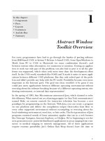
3 . The two-view projection ( Fig. 17.37 ) shows a ducting pipe. Construct a 3D model drawing of the pipe.
Place in a SW Isometric view; add lighting to the scene and a material to the model; and render.
Fig. 17.37 Exercise 3 – details of shapes and sizes
4 . A point marking device is shown in two two-view projections ( Fig. 17.38 ). The device is composed
of three parts – a base, an arm and a pin. Construct a 3D model of the assembled device and add
Fig. 17.38 Exercise 4 – details of shapes and sizes
Introduction to AutoCad 2009
Please purchase PDF Split-Merge on www.verypdf.com to remove this watermark.
Three-dimensional space
CHAPTER 17
339
appropriate materials to each part. Then add lighting to the scene and render in an SW Isometric view
( Fig. 17.39 ).
Fig. 17.39 Exercise 4 – a rendering
5. A rendering of a 3D model drawing of the connecting device shown in the orthographic projection
shown in Fig. 17.41 is given in Fig. 17.40 . Construct the 3D model drawing of the device and add a
suitable lighting to the scene. Then place in the ViewCube/Isometric view, add a material to the model
and render.
Fig. 17.40 Exercise 5 – a rendering
Fig. 17.41 Exercise 5 – two-view drawing
6. A fork connector and its rod are shown in a two-view projection in Fig. 17.42 . Construct a 3D model
drawing of the connector with its rod in position. Then add lighting to the scene, place in the ViewCube/
Isometric viewing position, add materials to the model and render.
Please purchase PDF Split-Merge on www.verypdf.com to remove this watermark.
CHAPTER 17
340
Fig. 17.43 Exercise 7 – details
Fig. 17.42 Exercise 6
7. An orthographic projection of the parts of a lathe steady are given in Fig. 17.43 . From the dimensions
shown in the drawing, construct an assembled 3D model of the lathe steady. When the 3D model has
been completed, add suitable lighting and materials and render the model ( Fig. 17.44 ).
Introduction to AutoCad 2009
Please purchase PDF Split-Merge on www.verypdf.com to remove this watermark.
Three-dimensional space
CHAPTER 17
341
Fig. 17.45 Exercise 8 – the box
Fig. 17.47 Exercise 9 – one of the solutions from which the surface was obtained
Fig. 17.46 Exercise 8 – the box and its lid
Fig. 17.44 Exercise 7 – a rendering
8 . Construct suitable polylines to sizes of your own discretion in order to form the two surfaces to form the
box shape shown in Fig. 17.45 with the aid of the Rulesurf tool. Add lighting and a material and render
the surfaces so formed. Construct another three Edgesurf surfaces to form a lid for the box. Place the
surface in a position above the box, add a material and render ( Fig. 17.46 ).
9 . Figure 17.47 shows a polyline for each of the 4 objects from which the surface shown in Fig. 17.48 was
obtained. Construct the surface and shade with Realistic shading.
Please purchase PDF Split-Merge on www.verypdf.com to remove this watermark.
CHAPTER 17
342
Fig. 17.51 Outlines of the three surfaces
10. The surface model for this exercise was constructed from 3 Edgesurf surfaces working to the suggested
objects for the surface as shown in Fig. 17.51 . The sizes of the outlines of the objects in each case are
Fig. 17.48 Exercise 9
Fig. 17.50 The three surfaces
Fig. 17.49 Exercise 10
Introduction to AutoCad 2009
Please purchase PDF Split-Merge on www.verypdf.com to remove this watermark.
Three-dimensional space
CHAPTER 17
343
Fig. 17.53 Exercise 11
Fig. 17.52 Exercise 11 – the circle and semicircle
left to your discretion. Figure 17.49 shows the completed surface model. Figure 17.50 shows the three
surfaces of the model separated from each other.
11. Figure 17.52 shows in a View Block/Isometric view a semicircle of radius 25 constructed in the View
Cube/Top view on a layer of colour Magenta with a semicircle of radius 75 constructed on the View
Block/Front view with its left-hand end centred on the semicircle. Figure 17.53 shows a surface
constructed from the two semicircles in a Visual Styles/Realistic mode.
Please purchase PDF Split-Merge on www.verypdf.com to remove this watermark.
This page intentionally left blank
Please purchase PDF Split-Merge on www.verypdf.com to remove this watermark.
345
Editing 3D solid
models
AIMS OF THIS CHAPTER
The aims of this chapter are:
1. to introduce the use of tools from the Solid Editing panel;
2. to show examples of a variety of 3D solid models.
Chapter 18
Please purchase PDF Split-Merge on www.verypdf.com to remove this watermark.
Introduction to AutoCad 2009
CHAPTER 18
346
The Solid Editing tools
The Solid Editing tools can be called from the Home/Solid Editing panel
( Fig. 18.1 ) or from the Solid Editing toolbar ( Fig. 18.2 ).
E x a mples of the results of using some of the Solid Editing tools are shown
in this chapter. These tools are of value if the design of a 3D solid model
needs to be changed (edited), although some are useful for constructing
parts of 3D solids which cannot easily be constructed using other tools.
Fig. 18.1 The Home/ Solid
Editing panel
Fig. 18.2 The Solid Editing toolbar
Fig. 18.3 First example – Extrude faces tool – fi rst stages
Fig. 18.4 The Extrude
faces tool from the Home /
Solid Editing panel
First example – Extrude faces tool ( Fig. 18.5 )
1. Set ISOLINES to 24.
2. In the ViewCube / Right construct a cylinder of radius 30 and height 30
( Fig. 18.3 ).
3. In the ViewCube / Front construct the pline shown in Fig. 18.3 . Mirror
the pline to the other end of the cylinder.
4. In the ViewCube / Top move the pline to lie central to the cylinder.
5. Place the screen in the ViewCube / Isometric .
6. Click the Extrude faces tool icon in the Home / Solid Editing panel
( Fig. 18.4 ). The command line shows:
Command: _solidedit
Solids editing automatic checking: SOLIDCHECK ϭ 1
Enter
a solids editing option [Face/Edge/Body/
Undo/eXit] Ͻ eXit Ͼ : _face
Enter
a face editing option
[Extrude/Move/Rotate/Offset/Taper/Delete/Copy/
coLor/mAterial/Undo/eXit] Ͻ eXit Ͼ : _extrude
Select faces or [Undo/Remove]: 2 faces found.
Select faces or [Undo/Remove/ALL]:
enter
r
right-click
Please purchase PDF Split-Merge on www.verypdf.com to remove this watermark.
Editing 3D solid models
CHAPTER 18
347
Remove faces or [Undo/Add/ALL]:
pick
1 face found,
1 removed.
Specify height of extrusion or [Path]:
enter
p
right-click
Select extrusion path:
pick
the path pline
Solid validation started.
Solid validation completed.
Enter
a face editing option [Extrude/Move/Rotate/
Offset/Taper/Delete/Copy/coLor/mAterial/Undo/
eXit] Ͻ eXit Ͼ :
right-click
Command:
7. Repeat the operation using the view at the other end of the cylinder.
8. Add lights and a material and r ender the 3D model ( Fig. 18.5 ).
Fig. 18.5 First example –
Extrude faces tool
N o t e
Note the prompt line which includes the statement
SOLIDCHECK ؍ 1 . If the variable SOLIDCHECK is set on (to 1 )
the prompt lines include the lines SOLIDCHECK ؍ 1 , Solid
validation started and Solid validation completed . If set to 0 these
two lines do not show.
Second example – Extrude faces tool ( Fig. 18.7 )
1. Construct a hexagonal extrusion just 1 unit high in the ViewCube/Top .
2. Change to the ViewCube/Front and construct the curved pline ( Fig. 18.6) .
3. Back in the Top view, move the pline to lie central to the extrusion.
4. Place in the ViewCube/Isometric and extrude the top face of the
extrusion along the path of the curved pline.
5. Add lighting and a material to the model and render ( Fig. 18.7 ).
Fig. 18.6 Second example –
Extrude faces tool – pline
for path
Fig. 18.7 Second example –
Extrude faces tool
N o t e
This example shows that a face of a 3D solid model can be extruded
along any suitable path curve. If the polygon on which the extrusion had
been based had been turned into a region, no extrusion could have taken
place. The polygon had to be extruded to give a face to a 3D solid.
Third example – Move faces tool ( Fig. 18.8 )
1. Construct the 3D solid drawing shown in the left-hand drawing of Fig. 18.8
from three boxes which have been united using the Union tool.
Please purchase PDF Split-Merge on www.verypdf.com to remove this watermark.
Introduction to AutoCad 2009
CHAPTER 18
348
2. Click on the Move faces tool in the Home/Solid Editing panel (see
Fig. 18.4 , page 344). The command line shows:
Command: _solidedit
[ prompts]: _face
Enter
a face editing option
[prompts]: _move
Select faces or [Undo/Remove]:
pick
face 1 face
found.
Select faces or [Undo/Remove/ALL]:
right-click
Specify a base point or displacement:
pick
Specify a second point of displacement:
pick
[further prompts]:
and the picked face is moved – right-hand drawing of Fig. 18.8 .
Fig. 18.8 Third example – Solid, Move faces tool
Fourth example – O set faces tool ( Fig. 18.9 )
1. Construct the 3D solid drawing shown in the left-hand drawing of
Fig. 18.9 from a hexagonal extrusion and a cylinder which have been
united using the Union tool.
2. Click on the Offset faces tool icon in the Home/Solid Editing toolbar
(see Fig. 18.4 ). The command line shows:
Command: _solidedit
[prompts]: _face
[prompts]
[prompts]: _offset
Select faces or [Undo/Remove]:
pick
the bottom
face of the 3D model 2 faces found.
Select faces or [Undo/Remove/All]:
enter
r
right-click
Select faces or [Undo/Remove/All]:
pick
highlighted faces other than the bottom face 2
faces found, 1 removed
Please purchase PDF Split-Merge on www.verypdf.com to remove this watermark.
Editing 3D solid models
CHAPTER 18
349
Select faces or [Undo/Remove/All]:
right-click
Specify the offset distance:
enter
30
right-click
3. Repeat, offsetting the upper face of the cylinder by 50 and the right-
hand face of the lower extrusion by 15 .
The results are shown in Fig. 18.9 .
Fifth example – Taper faces tool ( Fig. 18.10 )
1. Construct the 3D model as in the left-hand drawing of Fig. 18.10 .
Place in ViewCube/Isometric .
2. Call Taper faces . The command line shows:
Command: _solidedit
[prompts]: _face
[prompts]
[prompts]: _taper
Select faces or [Undo/Remove]:
pick
the upper face
of the base 2 faces found.
Select faces or [Undo/Remove/All]:
enter
r
right-click
Fig. 18.9 Third example – Offset faces tool
Fig. 18.10 Fifth example – Taper faces tool
Please purchase PDF Split-Merge on www.verypdf.com to remove this watermark.
Introduction to AutoCad 2009
CHAPTER 18
350
Select faces or [Undo/Remove/All]:
pick
highlighted faces other than the upper face 2
faces found, 1 removed
Select faces or [Undo/Remove/All]:
right-click
Specify the base point:
pick
a point on the
right-hand edge of the face
Specify the taper angle:
enter
10
right-click
and the selected face tapers as indicated in the right-hand drawing
( Fig. 18.10 ).
Sixth example – Copy faces tool ( Fig. 18.12 )
1. Construct a 3D model to the sizes as given in Fig. 18.11 .
Fig. 18.11 Sixth example – Copy faces tool – details of the 3D solid model
2. Click on the Copy faces tool in the Home/Solid Editing toolbar (see
Fig. 18.4 , page 344). The command line shows:
Command: _solidedit
[prompts]: _face
[prompts]
[prompts]: _copy
Select faces or [Undo/Remove]:
pick
the upper face
of the solid model 2 faces found.
Select faces or [Undo/Remove/All]:
enter
r
right-click
Select faces or [Undo/Remove/All]:
pick
highlighted face not to be copied 2 faces found,
1 removed
Select faces or [Undo/Remove/All]:
right-click
Please purchase PDF Split-Merge on www.verypdf.com to remove this watermark.
Editing 3D solid models
CHAPTER 18
351
Specify a base point or displacement:
pick
anywhere on the highlighted face
Specify a second point of displacement:
pick
a
point some 50 units above the face
3 . Add lights and a material to the 3D model and its copied face and
render ( Fig. 18.12 ).
Seventh example – Color faces tool ( Fig. 18.14 )
1. Construct a 3D model of the wheel to the sizes as shown in Fig. 18.13 .
Fig. 18.12 Sixth example –
Copy faces tool
Fig. 18.13 Seventh example – Color faces tool – details of the 3D model
2. Click the Color faces tool icon in the Home/Solid Editing toolbar (see
Fig. 18.4 , page 344). The command line shows:
Command: _solidedit
[prompts]: _face
[prompts]
[prompts]: _color
Select faces or [Undo/Remove]:
pick
the inner face
of the wheel 2 faces found
Select faces or [Undo/Remove/All]:
enter
r
right-click
Select faces or [Undo/Remove/All]:
pick
highlighted faces other than the required face 2
faces found, 1 removed
Enter
new color Ͻ ByLayer Ͼ :
enter
1 (which is red)
right-click
Please purchase PDF Split-Merge on www.verypdf.com to remove this watermark.
Introduction to AutoCad 2009
CHAPTER 18
352
Fig. 18.14 Seventh example – Color faces tool
Fig. 18.15 First example – 3D models – details of sizes and shapes
3. Add lights and a material to the edited 3D model and render
( Fig. 18.14 ).
Examples of more 3D models
These 3D models can be constructed in the acadiso3D.dwt screen. The
descriptions of the stages needed to construct these 3D models have been
reduced from those given in earlier pages, in the hope that readers have
already acquired a reasonable skill in the construction of such drawings.
First example ( Fig. 18.16 )
1. Front view. Construct the three extrusions for the back panel and the
two extruding panels to the details given in Fig. 18.15 .
Please purchase PDF Split-Merge on www.verypdf.com to remove this watermark.
Editing 3D solid models
CHAPTER 18
353
2. Top view. Move the two panels to the front of the body and union
the three extrusions. Construct the extrusions for the projecting parts
holding the pin.
3. Front view. Move the two extrusions into position and union them to
the back.
4. Top view. Construct two cylinders for the pin and its head.
5. Top view. Move the head to the pin and union the two cylinders.
6. Front view. Move the pin into its position in the holder. Add lights and
materials.
7. Isometric view. Render. Adjust lighting and materials as necessary
( Fig. 18.16 ).
Second example ( Fig. 18.18 )
1. Top ( Fig. 18.17 ). Construct polyline outlines for the body extrusion
and the solids of revolution for the two end parts. Extrude the body and
subtract its hole and using the Revolve tool form the two end solids of
revolution.
Fig. 18.16 First example –
3D models
Fig. 18.17 Second example – 3D models dimensions
2. Right . Move the two solids of revolution into their correct positions
relative to the body and union the three parts. Construct a cylinder for
the hole through the model.
3. Front . Move the cylinder to its correct position and subtract from the
model.
4. Top . Add lighting and a material.
5. Isometric . Render ( Fig. 18.18 ).
Third example ( Fig. 18.18 )
1. Front . Construct the three plines needed for the extrusions of each part
of the model (details, Fig. 18.19 ). Extrude to the given heights. Subtract
the hole from the 20 high extrusion.
Please purchase PDF Split-Merge on www.verypdf.com to remove this watermark.
CHAPTER 18
354
2. Top . Move the 60 extrusion and the 10 extrusion into their correct
positions relative to the 20 extrusion. With Union form a single 3D
model from the three extrusions.
3. Add suitable lighting and a material to the model.
4. Isometric . Render ( Fig. 18.20 ).
Fourth example ( Fig. 18.20 )
1. Front . Construct the polyline – left-hand drawing in Fig. 18.21 .
Fig. 18.19 Third example – 3D models – details of shapes and sizes
Fig. 18.20 Third example – 3D models
Fig. 18.18 Second example – 3D models
Introduction to AutoCad 2009
Please purchase PDF Split-Merge on www.verypdf.com to remove this watermark.
Editing 3D solid models
CHAPTER 18
355
2. With the Revolve tool from the Home/3D modeling panel construct a
solid of revolution from the pline.
3. Top . Add suitable lighting and a coloured glass material.
4. Isometric . Render – right-hand illustration in Fig. 18.21 .
Fig. 18.21 Fourth example – 3D models
Please purchase PDF Split-Merge on www.verypdf.com to remove this watermark.
CHAPTER 18
356
Exercises
Methods of constructing answers to the following exercises can be found in the free website:
Fig. 18.24 Exercise 2 – details of shapes and sizes
1 . Working to the shapes and dimensions as
given in the orthographic projection of
Fig. 18.22 , construct the exploded 3D model as
shown in Fig. 18.23 . When the model has been
constructed add suitable lighting and apply
materials, followed by rendering.
Fig. 18.22 Exercise 1 – orthographic projection
Fig. 18.23 Exercise 1 – rendered 3D model
Add suitable lighting and materials, place in
one of the isometric viewing positions and
render the model.
3 . Construct the 3D model shown in the
rendering (Fig. 18.26) from the details given in
the parts drawing of Fig. 18.27 .
2. Working to the dimensions given in the
orthographic projections of the three parts
of this 3D model ( Fig. 18.24 ), construct the
assembled parts as shown in the rendered 3D
model of Fig. 18.25 .
Introduction to AutoCad 2009
Fig. 18.25 Exercise 2
Please purchase PDF Split-Merge on www.verypdf.com to remove this watermark.
Editing 3D solid models
CHAPTER 18
357
Fig. 18.26 Exercise 3
Fig. 18.27 Exercise 3 – the parts drawing
Fig. 18.28 Exercise 4 – fi rst orthographic projection
4 . A more di cult exercise: a rendered 3D model
of the parts of an assembly are shown in
Fig. 18.31 . Working to the details given in the
three orthographic projections ( Figs. 18.28,
18.29 and 18.30 ), construct the two parts of
the 3D model, place them in suitable positions
relative to each other, add lighting and
materials and render the model.
Please purchase PDF Split-Merge on www.verypdf.com to remove this watermark.
CHAPTER 18
358
Fig. 18.30 Exercise 4 – third orthographic projection
Fig. 18.31 Exercise 4
Fig. 18.29 Exercise 4 – second orthographic projection
Introduction to AutoCad 2009
Please purchase PDF Split-Merge on www.verypdf.com to remove this watermark.
359
Other features of
3D modelling
AIMS OF THIS CHAPTER
The aims of this chapter are:
1. to give a further example of placing raster images in an AutoCAD drawing;
2. to give examples of methods of printing or plotting not given in previous chapters;
3. to give examples of polygonal viewports.
Chapter 19
Please purchase PDF Split-Merge on www.verypdf.com to remove this watermark.
Introduction to AutoCad 2009
CHAPTER 19
360
Raster images in AutoCAD drawings
Example – Raster image in a drawing ( Fig. 19.5 )
This example shows the raster fi le Fig14.bmp of the 3D model constructed
to the details given in the drawing of Fig. 19.1 .
Fig. 19.1 Example – Raster image in a drawing – details
Fig. 19.2 Selecting Image from the Blocks & References / References panel
Raster images are graphics images in fi les with fi le names ending with the
extensions *.bmp ; *.pcx ; *.tif ; and the like. The types of graphics fi les
which can be inserted into AutoCAD drawings can be seen by fi rst clicking
on the Image icon in the Blocks & References/Reference panel ( Fig.
19.2 ), which brings the Select Image File dialog ( Fig. 19.3 ) on screen.
In the dialog click the arrow to the right of the Files of type fi eld and
the pop-up list which appears lists the types of graphics fi les which can
be inserted into AutoCAD drawings. Such graphics fi les can be used to
describe in 3D the details shown in a 2D technical drawing.
1. Construct the 3D model to the shapes and sizes given in Fig. 19.1
working in four layers, each of a different colour.
2. Place in the ViewCube/Isometric view.
3. Shade the 3D model in Realistic visual style.
4. Zoom the shaded model to a suitable size and press the Print Scr key
of the keyboard.
Please purchase PDF Split-Merge on www.verypdf.com to remove this watermark.
Other features of 3D modelling
CHAPTER 19
361
5. Open the Windows Paint application and click Edit in the menu bar,
followed by another click on Paste in the drop-down menu. The whole
AutoCAD screen, which includes the shaded 3D assembled model,
appears.
6. Click the Select tool icon in the toolbar of Paint and window the 3D
model. Then click Copy in the Edit drop-down menu.
7. C lick New in the File drop-down menu, followed by a click on No in
the warning window which appears.
8. Click Paste in the Edit drop-down menu. The shaded 3D model
appears. Click Save As from the File drop-down menu and save the
bitmap to a suitable fi le name – in this example, Fig14.bmp .
Fig. 19.3 The Select Image File dialog
Fig. 19.4 Example – Raster image in a drawing – the Image dialog
9. Open the orthographic projection drawing of Fig. 19.1 in AutoCAD.
10. Open the Select Image File dialog and from the Look in fi eld select
the raster fi le Fig14.bmp from the fi le list ( Fig. 19.3 ). Another dialog
(Image ) opens ( Fig. 19.4 ) showing the name of the raster image fi le.
Please purchase PDF Split-Merge on www.verypdf.com to remove this watermark.
Introduction to AutoCad 2009
CHAPTER 19
362
Click the OK button of the dialog and a series of prompts appears at
the command line requesting position and scale of the image. Enter
appropriate responses to these prompts and the image appears in
position in the orthographic drawing ( Fig. 19.5 ).
Fig. 19.5 Example – Raster image in a drawing
N o t e
1. It will normally be necessary to enter a scale in response to the
prompt lines otherwise the raster image may appear very small on
screen. If it does it can be zoomed anyway.
2 . Place the image in position in the drawing area. In Fig. 19.5 the
orthographic projections have been placed within a margin and a
title block has been added.
Printing/Plotting
Hard copy (prints or plots on paper) from a variety of different types of
AutoCAD drawings of 3D models can be obtained. Some examples have
already been shown on p. 71 in Chapter 15 .
First example – Printing/plotting ( Fig. 19.8 )
If an attempt is made to print a multiple viewport screen with all viewport
drawings appearing in the plot, only the current viewport will be printed.
To print or plot all viewports proceed as folllows:
1. Open a 4-viewport screen of the assembled 3D model shown in the fi rst
example ( p. 362 ) .
Please purchase PDF Split-Merge on www.verypdf.com to remove this watermark.