Tài liệu Introduction to AutoCAD 2009 2D and 3D Design- P9 ppt
Bạn đang xem bản rút gọn của tài liệu. Xem và tải ngay bản đầy đủ của tài liệu tại đây (797.37 KB, 27 trang )
Introduction to AutoCad 2009
CHAPTER 21
388
Multileaders
There are a variety of uses for multileaders. The second example shows
one such use. The drawing in which multileaders are to be included is
shown in Fig. 21.4 .
1. In the Annotate/Multileaders panel click the Multileader Style icon
( Fig. 21.5 ). The Multileader Style Manager dialog appears. Click its
Modify button.
Fig. 21.4 Second example – multileaders. The drawing to which multileaders are to be added
Fig. 21.3 First example – annotation scaling. The front views scaled to 1:50
Please purchase PDF Split-Merge on www.verypdf.com to remove this watermark.
Design and AutoCAD 2009
CHAPTER 21
389
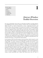
2. In the Modify Multileaders Style Standard dialog which appears,
make entries as shown in Fig. 21.6 .
3. Click the Multileader icon in the panel.
4. In the drawing, in response to prompts at the command line, add
multileaders one after the other to the drawing shown in Fig. 21.4 ,
numbering the parts 1 to 4 . See Fig. 21.7 .
Fig. 21.5 Second example – Multileader Style icon in the Annotate / Multileaders panel
System requirements for running AutoCAD 2009
● Note: there are two editions of AutoCAD 2009 – 32 bit and 64 bit
editions.
● Operating system: Windows XP Professional, Windows XP
Professional (x64 Edition), Windows XP Home Edition, Windows 2000
or Windows Vista 32 bit, Windows Vista 64 bit.
● Microsoft Internet Explorer 7.0 .
● Processor: Pentium III 800 Mhz.
● Ram: at least 128 MB.
Fig. 21.6 Second example – Modify Multileaders Style Standard dialog
Please purchase PDF Split-Merge on www.verypdf.com to remove this watermark.
Introduction to AutoCad 2009
CHAPTER 21
390
● Monitor screen: 1024 ϫ 768 VGA with True Colour as a minimum.
● Hard disk: a minimum of 300 MB.
● Graphics card: an AutoCAD certifi ed graphics card. Details can
be found on the web page AutoCAD Certifi ed Hardware XML
Database .
Fig. 21.7 Second example – multileaders
Please purchase PDF Split-Merge on www.verypdf.com to remove this watermark.
Appendices
Part 4
Please purchase PDF Split-Merge on www.verypdf.com to remove this watermark.
This page intentionally left blank
Please purchase PDF Split-Merge on www.verypdf.com to remove this watermark.
393
Printing/plotting
Appendix A
Please purchase PDF Split-Merge on www.verypdf.com to remove this watermark.
Introduction to AutoCad 2009
APPENDIX A
394
Introduction
S o me suggestions for printing/plotting of AutoCAD drawings have
already been given (pp. 297–299) . Plotters or printers can be selected
from a wide range of different types and are used for printing or plotting
drawings constructed in AutoCAD 2009. The example given here is from
a print using one of the default printers connected to the computer that the
author was using. However, if another plotter or printer is connected to
the computer, its driver can be set by fi rst opening the Windows Control
Panel , and with a double-click on the Autodesk Plotter Manager icon the
Plotters dialogs appear ( Fig. A.1 ).
Fig. A.1 The Plotters window
Double-click on the Add, remove or change plotter properties icon
and the Plotter Confi guration Editor dialog appears. Add settings as
required in the fi rst of the dialogs from this editor ( Fig. A.2 ). There are
several more dialogs in the series in which selections will need to be made
before completing the setting up of a printer or plotter for the printing of
AutoCAD drawings.
Note
1. AutoCAD drawings can be printed from the default printers
already installed in the Windows system of the computer on which
AutoCAD 2009 is loaded.
2. Plots or prints from drawings constructed in AutoCAD 2009 can be
made from either Model Space or from Paper Space.
Please purchase PDF Split-Merge on www.verypdf.com to remove this watermark.
Printing/plotting
APPENDIX A
395
An example of a printout
1. Either select Plot with a click on icon in the Output/Plot panel ( Fig. A.3 )
or from the File drop-down menu. The Plot dialog appears ( Fig. A.4 )
Fig. A2 The fi rst of the series of Plotter Confi guration Editor dialogs
Fig. A3 The Plot tool icon in the Output/Plot panel
2. There are two parts to the Plot dialog. Figure A4 shows both parts.
A click on the arrow at the bottom-right-hand corner of the dialog
closes to reveal only the left-hand part and vice versa.
3. Select an appropriate printer or plotter from the Printer/Plotter list.
In this example this is a colour printer. Then select the correct
paper size from the Paper Size pop-up list. Next, select what is to
be printed/plotted from the What to Plot pop-up list – in the example
shown this is Display . Click the Properties button and in the Custom
Properties dialog (not shown) set orientation to Landscape (dot
in radio button). Then click the Preview button of the Plot dialog.
Please purchase PDF Split-Merge on www.verypdf.com to remove this watermark.
Introduction to AutoCad 2009
APPENDIX A
396
4. A preview of the drawing to be printed/plotted appears ( Fig. A.5 ). If
satisfi ed with the preview, right-click and from the menu which appears
click Plot . If not satisfi ed click Exit . The preview disappears and the
Plot dialog reappears. Make changes as required from an inspection of
the preview and carry on in this manner until a plot can be made.
Fig. A4 The Plot dialog
Fig. A.5 The Plot Preview window with its right-click menu
Please purchase PDF Split-Merge on www.verypdf.com to remove this watermark.
397
List of tools
Appendix B
Please purchase PDF Split-Merge on www.verypdf.com to remove this watermark.
Introduction to AutoCad 2009
APPENDIX B
398
Introduction
AutoCAD 2009 allows the use of over 300 tools. Some operators prefer
using the word ‘ commands ’ , although command as an alternative to tool
is not in common use today. The majority of these tools are described
in this list. Many of the tools described here have not been used in this
book, because it is an introductory text designed to initiate readers into
the basic methods of using AutoCAD 2009. It is hoped the list will
encourage readers to experiment with those tools not described in the
book. The abbreviations for tools which can be abbreviated are included
in parentheses after the tool name. Tool names can be entered in upper or
lower case.
A list of 2D tools is followed by a listing of 3D tools. Internet tools
are described at the end of this listing. Not all of the tools available in
AutoCAD 2009 are shown here.
2D tools
About – Brings the About AutoCAD bitmap on screen
Adcenter (dc) – Brings the DesignCenter palette on screen
Align (al) – Aligns objects between chosen points
Appload – Brings the Load/Unload Applications dialog to screen
Arc (a) – Creates an arc
Area – States in square units of the area selected from a number of points
Array (ar) – Creates Rectangular or Polar arrays in 2D
Ase – Brings the dbConnect Manager on screen
Attdef – Brings the Attribute Defi nition dialog on screen
Attedit – Allows editing of attributes from the Command line
Audit – Checks and fi xes any errors in a drawing
Autopublish – Creates a DWF fi le for the drawing on screen
Bhatch (h) – Brings the Boundary Hatch dialog on screen
Block – Brings the Block Defi nition dialog on screen
Bmake (b) – Brings the Block Defi nition dialog on screen
Bmpout – Brings the Create Raster File dialog on screen
Boundary (bo) – Brings the Boundary Creation dialog on screen
Break (br) – Breaks an object into parts
Cal – Calculates mathematical expressions
Chamfer (cha) – Creates a chamfer between two entities
Chprop (ch) – Brings the Properties window on screen
Circle (c) – Creates a circle
Copy
(co) – Creates single or multiple copies of selected entities
Copyclip (Ctrl ϩ C) – Copies a drawing, or part of a drawing for inserting
into a document from another application
Copylink – Forms a link between an AutoCAD drawing and its
appearance in another application such as a word processing package
Please purchase PDF Split-Merge on www.verypdf.com to remove this watermark.
List of tools
APPENDIX B
399
Copytolayer – Copies objects from one layer to another
Customize – Brings the Customize dialog to screen, allowing the
customization of toolbars, palettes etc.
Dashboard – Has the same action as Ribbon
Dashboardclose – Closes the Ribbon
Ddattdef (at) – Brings the Attribute Defi nition dialog to screen
Ddatte (ate) – Edits individual attribute values
Ddcolor (col) – Brings the Select Color dialog on screen
Ddedit (ed) – The Text Formatting dialog box appears on selecting text
Ddim (d) – Brings the Dimension Style Manager dialog box on screen
Ddinsert (i) – Brings the Insert dialog on screen
Ddmodify – Brings the Properties window on screen
Ddosnap (os) – Brings the Drafting Settings dialog on screen
Ddptype – Brings the Point Style dialog on screen
Ddrmodes (rm) – Brings the Drafting Settings dialog on screen
Ddunits (un) – Brings the Drawing Units dialog on screen
Ddview (v) – Brings the View Manager on screen
Del – Allows a fi le (or any fi le) to be deleted
Dgnexport – Creates a MicroStation V8 dgn fi le from the drawing on
screen
Dgnimport – Allows a MicroStation V8 dgn fi le to be imported as an
AutoCAD dwg fi le
Dim – Starts a session of dimensioning
Dim1 – Allows the addition of a single addition of a dimension to a
drawing
Dimension tools – The Dimension
toolbar contains the following tools:
Linear , Aligned , Arc Length , Ordinate , Radius , Jogged , Diameter ,
Angular , Quick Dimension , Baseline , Continue , Quick Leader ,
Tolerance , Center Mark , Dimension Edit , Dimension Edit Text ,
Update and Dimension Style
Dist (di) – Measures the distance between two points in coordinate units
Distantlight – Creates a distant light
Divide (div) – Divides and entity into equal parts
Donut (do) – Creates a donut
Dsviewer – Brings the Aerial View window on screen
Dtext (dt) – Creates dynamic text. Text appears in drawing area as it is
entered
Dxbin – Brings the Select DXB File dialog on screen
Dxfi n – Brings the Select File dialog on screen
Dxfout – Brings the Save Drawing As dialog on screen
Ellipse (el) – Creates an ellipse
Erase (e) – Erases selected entities from a drawing
Exit – Ends a drawing session and closes AutoCAD 2009
Explode (x) – Explodes a block or group into its various entities
Explorer – Brings the Windows
Explorer on screen
Export (exp) – Brings the Export Data dialog on screen
Extend (ex) – To extend an entity to another
Please purchase PDF Split-Merge on www.verypdf.com to remove this watermark.
Introduction to AutoCad 2009
APPENDIX B
400
Fillet (f) – Creates a fi llet between two entities
Filter – Brings the Object Selection Filters dialog on screen
Gradient – Brings the Hatch and Gradient dialog on screen
Group (g) – Brings the Object Grouping dialog on screen
Hatch – Allows hatching by the entry responses to prompts
Hatchedit (he) – Allows editing of associative hatching
Help – Brings the AutoCAD 2009 Help: User Documentation dialog on
screen
Hide (hi) – To hide hidden lines in 3D models
Id – Identifi es a point on screen in coordinate units
Iimageattach (iat) – Brings the Select Image File dialog on screen
Iinsertobj – Brings the Insert Object dialog on screen
Imageadjust (iad) – Allows adjustment of images
Imageclip – Allows clipping of images
Import – Brings the Import File dialog on screen
Insert (i) – Brings the Inert dialog on screen
Isoplane (Ctrl/E) – Sets the isoplane when constructing an isometric
drawing
Join (j) – Joins lines which are in line with each other or arcs which are
from the same centre point
Laycur – Changes layer of selected objects to current layer
Laydel – Deletes and purges a layer with its contents
Layer (la) – Brings the Layer Properties Manager dialog on screen
Layout – Allows editing of layouts
Lengthen (len) – Lengthens an entity on screen
Limits – Sets the drawing limits in coordinate units
Line (l) – Creates a line
Linetype (lt) – Brings the Linetype Manager
dialog on screen
List (li) – Lists in a text window details of any entity or group of entities
selected
Load – Brings the Select Shape File
dialog on screen
Ltscale (lts) – Allows the linetype scale to be adjusted
Measure (me) – Allows measured intervals to be placed along entities
Menu – Brings the Select Customization File dialog on screen
Menuload – Brings the Load/Unload Customizations dialog on screen
Mirror (mi) – Creates an identical mirror image to selected entities
Mledit – Brings the Multiline Edit Tools dialog on screen
Mline (ml) – Creates mlines
Mlstyle – Brings the Multiline Styles dialog on screen
Move (m) – Allows selected entities to be moved
Mslide – Brings the Create Slide File dialog on screen
Mspace (ms) – When in PSpace changes to MSpace
Mtext (mt or t) – Brings the Multiline Text Editor on screen
Mview (mv) – To make settings of viewports in Paper Space
Mvsetup – Allows drawing specifi cations to be set up
New (Ctrl ϩ N) – Brings the Select template dialog on screen
Notepad – For editing fi les from the Windows Notepad
Please purchase PDF Split-Merge on www.verypdf.com to remove this watermark.
List of tools
APPENDIX B
401
Offset (o) – Offsets selected entity by a stated distance
Oops – Cancels the effect of using Erase
Open – Brings the Select File dialog on screen
Options – Brings the Options dialog to screen
Ortho – Allows ortho to be set ON/OFF
Osnap (os) – Brings the Drafting Settings dialog to screen
Pagesetup – Brings either the Page Setup Manager on screen
Pan (p) – Drags a drawing in any direction
Pbrush – Brings Windows Paint on screen
Pedit (pe) – Allows editing of polylines. One of the options is Multiple
allowing continuous editing of polylines without closing the command
Pline (pl) – Creates a polyline
Plot (Ctrl ϩ P) – Brings the Plot dialog to screen
Point (po) – Allows a point to be placed on screen
Polygon (pol) – Creates a polygon
Polyline (pl) – Creates a polyline
Preferences (pr) – Brings the Options dialog on screen
Preview (pre) – Brings the print/plot preview box on screen
Properties – Brings the Properties palette on screen
Psfi ll – Allows polylines to be fi lled with patterns
Psout – Brings the Create Postscript File dialog on screen
Purge (pu) – Purges unwanted data from a drawing before saving to fi le
Qsave – Saves the drawing fi le to its current name in AutoCAD 2009
Quickcalc (qc) – Brings the QUICKCALC palette to screen
Quit – Ends a drawing session and closes down AutoCAD 2009
Ray – A construction line from a point
Recover – Brings the Select File dialog on screen to allow recovery of
selected drawings as necessary
Recoverall – Repairs damaged drawing
Rectang (rec) – Creates a pline rectangle
Redefi ne
– If an AutoCAD command name has been turned off by
Undefi ne , Redefi ne turns the command name back on
Redo – Cancels the last Undo
Redraw (r) – Redraws the contents of the AutoCAD 2009 drawing area
Redrawall (ra) – Redraws the whole of a drawing
Regen (re) – Regenerates the contents of the AutoCAD 2009 drawing area
Regenall (rea) – Regenerates the whole of a drawing
Region (reg) – Creates a region from an area within a boundary
Rename (ren) – Brings the Rename dialog on screen
Revcloud – Forms a cloud-like outline around objects in a drawing to
which attention needs to be drawn
Ribbon – Brings the ribbon on screen
Ribbonclose – Closes the ribbon
Save (Ctrl ϩ S) – Brings the Save Drawing As dialog box on screen
Saveas – Brings the Save Drawing As dialog box on screen
Saveimg – Brings the Render Output File dialog on screen
Scale (sc) – Allows selected entities to be scaled in size – smaller or larger
Please purchase PDF Split-Merge on www.verypdf.com to remove this watermark.
Introduction to AutoCad 2009
APPENDIX B
402
Script (scr) – Brings the Select Script File dialog on screen
Setvar (set) – Can be used to bring a list of the settings of set variables
into an AutoCAD Text window
Shape – Inserts an already loaded shape into a drawing
Shell – Allows MS-DOS commands to be entered
Sketch – Allows freehand sketching
Solid (so) – Creates a fi lled outline in triangular parts
Spell (sp) – Brings the Check Spelling dialog on screen
Spline (spl) – Creates a spline curve through selected points
Splinedit (spe) – Allows the editing of a spline curve
Status – Shows the status (particularly memory use) in a Text window
Stretch (s) – Allows selected entities to be stretched
Style (st) – Brings the Text Styles dialog on screen
Tablet (ta) – Allows a tablet to be used with a pointing device
Tbconfi g – Brings the Customize dialog on screen to allow confi guration
of a toolbar
Text – Allows text from the Command line to be entered into a drawing
Thickness (th) – Sets the thickness for the Elevation command
Tilemode – Allows settings to enable Paper Space
Tolerance – Brings the Geometric Tolerance dialog on screen
Toolbar (to) – Brings the Customize User Interface dialog on screen
Trim (tr) – Allows entities to be trimmed up to other entities
Type – Types the contents of a named fi le to screen
UCS – Allows selection of UCS (user Coordinate System) facilites
Undefi ne – Suppresses an AutoCAD command name
Undo (u) (Ctrl ϩ Z) – Undoes the last action of a tool
View – Brings the View dialog on screen
Vplayer
– Controls the visibility of layers in Paperspace
Vports – Brings the Viewports dialog on screen
Vslide – Brings the Select Slide File dialog on screen
Wblock (w) – Brings the Create Drawing File dialog on screen
Wipeout – forms a polygonal outline within which all crossed parts of
objects are erased
Wmfi n – Brings the Import WMF dialog on screen
Wmfopts – Brings the WMF in Options dialog on screen
Wmfout – Brings the Create WMF File dialog on screen
Xattach (xa) – Brings the Select Reference File dialog on screen
Xline – Creates a construction line
Xref (xr) – Brings the Xref Manager dialog on screen
Zoom (z) – Brings the zoom tool into action
3D tools
3Darray – Creates an array of 3D models in 3D space
3Dcorbit – Allows methods of manipulating 3D models on screen
Please purchase PDF Split-Merge on www.verypdf.com to remove this watermark.
List of tools
APPENDIX B
403
3Ddistance – Allows the controlling of the distance of 3D models from the
operator
3Ddwf – Brings up the Export 3D DWF dialog
3Dface (3f) – Creates a 3 or 4 sided 3D mesh behind which other features
can be hidden
3Dfl y – Allows walkthroughs in any 3D plane
3Dforbit – controls the viewing of 3D models without constraint
3Dmesh – Creates a 3D mesh in 3D space
3Dmove – Shows a 3D move icon
3Dorbit (3do) – Allows a continuous movement and other methods of
manipulation of 3D models on screen
3Dorbitctr – Allows further and a variety of other methods of
manipulation of 3D models on screen
3Dpan – Allows the panning of 3D models vertically and horizontally on
screen
3Drotate – Displays a 3D rotate icon
3Dsin – Brings the 3D Studio File Import dialog on screen
3Dsout – Brings the 3D Studio Output File dialog on screen
3Dwalk – Starts walk mode in 3D
Align – Allows selected entities to be aligned to selected points in
3D space
Ameconvert – Converts AME solid models (from Release 12) into
AutoCAD 2000 solid models
Anipath – Opens the Motion Path Animation dialog
Box – Creates a 3D solid box
Cone – Creates a 3D model of a cone
Convertoldlights – Converts lighting from previous releases to AutoCAD
2009 lighting
Convertoldmaterials – Converts materials fro
m previous releases to
AutoCAD 2009 materials
Convtosolid – Converts plines and circles with thickness to 3D solids
Convtosurface – Converts objects to surfaces
Cylinder – Creates a 3D cylinder
Dducs (uc) – Brings the UCS dialog on screen
Edgesurf – Creates a 3D mesh surface from four adjoining edges
Extrude (ext) – Extrudes a closed polyline
Flatshot – Brings the Flatshot dialog to screen
Freepoint – Point light created without settings
Freespot – Spot light created without settings
Helix – Construct a helix
Interfere – Creates an interference solid from selection of several solids
Intersect (in) – Creates an intersection solid from a group of solids
Light – Enables different forms of lighting to be placed in a scene
Lightlist – Opens the Lights in Model palette
Loft – Activates the Loft command
Materials – Opens the Materials palette
Matlib – Outdated instruction
Please purchase PDF Split-Merge on www.verypdf.com to remove this watermark.
Introduction to AutoCad 2009
APPENDIX B
404
Mirror3d – Mirrors 3D models in 3D space in selected directions
Mview (mv) – When in PSpace brings in MSpace objects
Pface – Allows the construction of a 3D mesh through a number of
selected vertices
Plan – Allows a drawing in 3D space to be seen in plan (UCS World)
Planesurf – Creates a planar surface
Pointlight – Allows a point light to be created
Pspace (ps) – Changes MSpace to PSpace
Pyramid – Creates a pyramid
-render – can be used to make rendering settings from the command line.
Note the hyphen ( - ) must precede render
Renderpresets – Opens the Render Presets Manager dialog
Renderwin – Opens the Render window
Revolve (rev) – Forms a solid of revolution from outlines
Revsurf – Creates a solid of revolution from a pline
Rmat – Brings the Materials palette on screen
Rpref (rpr) – Opens the Advanced Render Settings palette
Section (sec) – Creates a section plane in a 3D model
Shade (sha) – Shades a selected 3D model
Slice (sl) – Allows a 3D model to be cut into several parts
Solprof – Creates a profi le from a 3D solid model drawing
Sphere – Creates a 3D solid model sphere
Spotlight – Creates a spotlight
Stlout – Saves a 3D model drawing in ASCII or binary format
Sunproperties – Opens the Sun Properties palette
Sweep – Creates a 3D model from a 2D outline along a path
Tabsurf – Creates a 3D solid from an outline and a direction vector
Torus (tor) – Allows a 3D torus to be created
Ucs – Allows settings of the UCS plane
Ucs – Allows settings of the UCS plane
Union (uni) – Unites 3D solids into a single solid
View – Creates view settings for 3D models
Visualstyles – Opens the Visual Styles Manager palette
Vpoint – Allows viewing positions to be set from x,y,z entries
Vports – Brings the Viewports dialog on screen
Wedge (we) – Creates a 3D solid in the shape of a wedge
Xedges – Creates a 3D wireframe for a 3D solid
Internet tools
Etransmit – Brings the Create Transmittal dialog to screen
Publish – Brings the Publish dialog to screen
Please purchase PDF Split-Merge on www.verypdf.com to remove this watermark.
405
Some set variables
Appendix C
Please purchase PDF Split-Merge on www.verypdf.com to remove this watermark.
Introduction to AutoCad 2009
APPENDIX C
406
Introduction
AutoCAD 2009 is controlled by a large number of variables (over 460
in number), the settings of many of which are determined when making
entries in dialogs. Others have to be set at the command line. Some are
read-only variables which depend upon the confi guration of AutoCAD
2009 when it is originally loaded into a computer (default values). Only a
limited number of the variables are shown here.
A list of those set variables follows which are of interest in that they often
require setting by entering fi gures or letters at the command line. To set a
variable, enter its name at the command line and respond to the prompts
which arise.
To see all set variables, enter set (or setvar ) at the command line:
Command:
enter
set
right-click
SETVAR
Enter
variable name or ?:
enter
?
Enter
variable name to list ʚ * ʛ :
right-click
and a Text window opens showing a fi rst window with a list of the
fi rst of the variables. To continue with the list press the Return
key when prompted and at each press of the Return key another
window opens.
To see the settings for each set variable enter the name of the variable at
the command line, followed by pressing the F1 key which brings up the
Help screen; click the search tab, followed by entering set variables in
the Ask fi eld. From the list then displayed the various settings of all set
variables can be read.
Some of the set variables
ANGDIR – Sets angle direction. 0 counterclockwise; 1
clockwise
APERTURE – Sets size of pick box in pixels
AUTODWFPUBLISH – Sets Autopublish on or off
BLIPMODE – Set to 1 marker blips show; set to 0 no blips
COMMANDLINE – Opens the command line palette.
COMMANDLINEHIDE – Closes the command line palette
COPYMODE – Sets whether Copy repeats
Please purchase PDF Split-Merge on www.verypdf.com to remove this watermark.
Some set variables
APPENDIX C
407
Note
DIM variables – There are over 70 variables for setting dimensioning,
but most are in any case set in the Dimension Styles dialog or as
dimensioning proceeds. However, one series of the Dim variables may
be of interest:
DMBLOCK – Sets a name for the block drawn for an operator’s own
arrowheads. These are drawn in unit sizes and saved as required
DIMBLK1 – Operator’s arrowhead for fi rst end of line
DIMBLK2 – Operator’s arrowhead for other end of line
DRAGMODE – Set to 0 no dragging; set to 1 dragging on; set to 2
automatic dragging
DRAG1 – Sets regeneration drag sampling. Initial value is 10
DRAG2 – Sets fast dragging regeneration rate. Initial value is 25
FILEDIA – Set to 0 disables Open and Save As dialogs; set to 1 enables
these dialogs
FILLMODE – Set to 0 hatched areas are fi lled with hatching. Set to 0
hatched areas are not fi lled. Set to 0 and plines are not fi lled.
GRIPS – set to 1 and grips show. Set to 0 and grips do not show.
LIGHTINGUNITS – set to 1 (international) or 2 (USA) for photometric
lighting to function
MBUTTONPAN – Set to 0 on right-click menu with the Intellimouse. Set
to 1 Intellimouse right-click menu on
MIRRTEXT
– Set to 0 text direction is retained; set to 1 text is mirrored
NAVVCUBE – Sets the ViewCube
on/off
NAVVCUBELOCATION – Controls the position of th ViewCube
between top-right ( 0 ) and bottom-left ( 3 )
NAVVCUBEOPACITY – Controls the opacity of the ViewCube from 0
(hidden) to 100 (dark)
NAVVCUBESIZE – controls the size of the ViewCube between 0 (small)
to 2 (large)
PELLIPSE – Set to 0 creates true ellipses; set to 1 polyline ellipses
PERSPECTIVE – Set to 0 places the drawing area into parallel
projection. Set to 1 places the drawing area into perspective projection
PICKBOX – Sets selection pick box height in pixels
Please purchase PDF Split-Merge on www.verypdf.com to remove this watermark.
Introduction to AutoCad 2009
APPENDIX C
408
PICKDRAG – Set to 0 selection windows picked by two corners; set to 1
selection windows are dragged from corner to corner
RASTERPREVIEW – set to 0 , raster preview images not created with
drawing. Set to 1 , preview image created
SHORTCUTMENU – For controlling how right-click menus show:
0 all disabled; 1 default menus only; 2 edit mode menus; 4 command mode
menus; 8 command mode menus when options are currently available.
Adding the fi gures enables more than one option.
SURFTAB1 – Sets mesh density in the M direction for surfaces generated
by the Surfaces tools
SURFTAB2 – Sets mesh density in the N direction for surfaces generated
by the Surfaces tools
TEXTFILL – Set to 0 , True Type text shows as outlines only; set to 1 ,
True Type text is fi lled
TiILEMODE – Set to 0 Paperspace enabled; set to 1 tiled viewports in
Modelspace
TOOLTIPS – Set to 0 no tool tips; set to 1 tool tips enabled
TPSTATE – Set to 0 and the Tool Palettes window is inactive. Set to 1
and the Tool Palettes window is active
TRIMMODE – Set to 0
edges not trimmed when Chamfer and Fillet
are used; set to 1 edges are trimmed
UCSFOLLOW – Set to 0 new UCS settings do not take effect; set to 1
UCS settings follow requested settings
UCSICON
– Set OFF UCS icon does not show; set to ON it shows
Please purchase PDF Split-Merge on www.verypdf.com to remove this watermark.
409
*.3ds , 188
*.bmp , 194
*.bmp fi les , 360
*.dgn , 199
*.dwg , 52
*.dxf , 185
*.eps , 183 , 194
*.jpg , 194
*.pcx , 194 , 360
*.tga , 194
*.tif , 194 , 360
2D Annotation and Drafting workspace , 26
2D coordinates , 14
2D Drafting & Annotation , 4 , 89
2D objects in 3D space , 330
2D outlines for 3D , 214
2D tools , 398
2P circles , 33
3D Array tool , 254 , 255
3D coordinates , 15
3D DYN , 64
3D Mirror tool , 257
3D model 252
3D models of buildings , 308
3D model libraries , 250
3D Modeling workspace , 4 , 210 , 274
3D Navigate , 335
3D Objects tools , 232
3D Rotate tool , 258
3D solid model examples , 352
3D space , 322
3D Studio , 188
3D Surfaces , 268
3D template , 274
3D tools , 398
3dorbit tool , 294
3P circles , 33
3point , 327 , 330
A3 template , 88
Absolute coordinate entry , 31 , 43
Acadiso , 87
Acadiso.dwt , 16 , 27 , 87
Acadiso3D.dwt template , 287
Adding a material to a model , 291
Advanced hatching , 161
Advanced Render Settings , 285 , 292
Advanced Settings palette , 287
Aerial View window , 78
Aligned Dimension tool , 124
All zoom , 76
A mbient lighting , 283
Angles , 31
Angular dimensions , 127
Annotate/Dimensions panel
, 122
Annotate/Multileaders panel , 388
Annotation scaling , 387
ANSI hatches , 156
Application Status Bar Menu , 13
Arc Length tool , 130
Arc tool , 49
Arial , 81
Array , 97 , 115
Array dialog , 99
Array tool , 253
Associative hatching , 156
AutoCAD 2007 DXF [*.dxf] , 185
AutoCAD Classic workspace , 4 , 19 , 89
AutoCAD drawing fi
le extension , 52
AutoCAD SHX fonts , 138
AutoCAD Text Window , 134
AutoCAD window , 4
Autodesk DWF Viewer , 203
Autodesk Plotter Manager , 394
AutoHide , 5
Available materials in drawing , 281
Background colour , 284
Block Defi nition dialog , 169
Blocks , 168
Blocks & Reference/Block panel , 250
Blocks & References/ Reference panel , 186
Boolean operators , 227
Borders , 16
Box tool , 221 , 241
Break tool , 108 , 115
Browse for Drawing File dialog , 176
Building drawings , 304
Building views , 304
Buttons , 11
Index
Please purchase PDF Split-Merge on www.verypdf.com to remove this watermark.
Index
410
Calling tools , 48
Center zoom , 76
Chamfer , 115
Chamfer tool , 112 , 224
Check boxes , 1
Check Spelling dialog , 137
Circle tool , 6 , 33
Clear Screen icon , 19
Click , 43
Clipboard , 182
Close button , 28
Close dialog button , 11
Color Faces tool , 351
Color Gradient hatching , 164
Command call methods , 212
Command line dimensions , 125
Command palette , 5 , 274
Commandllinehide , 57
Conceptual style , 240 , 255
Cone tool , 223
Confi rm Password dialog , 376
Control Panel , 394
Coordinate system , 14
Coordinates , 31
Copy Faces tool , 350
Copy Link , 182
Copy tool , 92 , 114
Create Sheet Set dialogs , 198
Create tool , 168 , 250
Create Transmittal dialog , 378
Ctrl ϩ 9 , 5 7
Ctrl ϩ E , 148
Cursor pick box , 27
Customer User Interface dialog , 21
Customization , 21
Cylinder tool , 222
Data Exchange Format fi les , 185
Ddedit , 136
Default Distant light , 289
Default Template File Name , 275
Deferred Tangent tip , 35
Design , 384
Design brief , 384
Design chart , 385
Design Web Format , 199
DesignCenter , 172 , 177 , 250
DesignCenter palette
, 8 , 172
Dgnexport , 191
Dgnimport , 191
Dialog , 43
Dimension Style , 80
Dimension Style Manager , 80 , 131 , 138
Dimension tolerances , 131
Dimension toolbar , 122
Dimension tools , 122
Dimensions abbreviations , 125
Dimensions Style Manager , 81
Distant lights , 284
Docking palettes , 276
Double-click , 43
Drafting Settings , 13 , 53
Drag , 43
Draw drop-down menu , 50
Draw toolbar , 19 , 26 , 50 , 89
Draw tools , 26
Draw/Modeling drop-down menu , 211
Drawing template , 18 , 86
Drawing Units dialog , 17
Drawing Window Colors dialog , 275
Dsviewer , 78
DWF format , 202
DXF fi les , 185
DYN , 13 , 56 , 228 , 267
DYN 3D , 64
Dynamic Input , 56 , 267
Dynamic Input button , 228
Dynamic UCS , 13
Dynamic zoom , 76
Edgesurf tool , 334
Edit tools , 194
Ellipse tool , 50 , 149
E mailing , 203 , 376
Enable i-drop , 377
Encapsulated PS fi le , 183
End view , 142
Enhancements , 386
Enter , 43
Entries at command line , 18
Erase tool , 33 , 92 , 115
Etransmit tool , 378
Evaluation , 386
Explode , 92 , 115 , 170 , 252
Export Data dialog , 183
Export tool , 183
Extend tool , 111
Extents zoom , 76
External Reference dialog , 190
External References , 188
Extrude Faces tool , 346, 347
Extrude tool , 217 , 241
Please purchase PDF Split-Merge on www.verypdf.com to remove this watermark.
Index
411
F8 key , 32
F9 key , 27
Face tool , 332
Fence, fi elds and road construction , 313
Field , 70
File drop-down menu , 28
Fillet tool , 112 , 115 , 224 , 333
First angle projection , 144
Floor layouts , 307
Floppy disk , 52
Flyouts , 21
Fonts , 81
Four: Equal viewports , 240
Four:Left viewports , 244
Free Orbit , 294
Front view , 142
Function keys , 12
Garage , 311
Generic Lights palette , 289
Gradient hatching , 159
Graphics Card , 388
Grid , 12 , 16 , 26 , 80 , 275
Hard disk , 390
Hardcopy , 296 , 362
Hatch and Gradient dialog , 146 , 180
Hatch icon , 146
Hatch Pattern palette , 156
Hatching , 145 , 156
Hatching and text , 161
Hatching rules , 157
Helix tool , 265
Home panels , 21
Home/3D Modeling panel , 211 , 229 , 241
Home/Annotation panel , 135
Home/Block panel , 170
Home/Draw panel , 5 , 26 , 33 , 38 , 49 , 64 , 103
Home/Layers panel , 84 , 126 , 142
Home/Modify panel , 33 , 67 , 92 , 173 , 25
Home/Solid Editing panel , 215 , 346
Home/Utilities panel , 76 , 182
Home/View/Conceptual style , 331
I mage dialog , 187 , 361
I mage icon , 186
InfoCenter , 379
Insert dialog , 170
Insert tool icon , 170
Inserting 3D blocks , 250
Inserting blocks , 170
Intensity factor , 291
Internet explorer , 389
Internet tools , 404
Intersect tool , 216
ISO hatches , 156
Isocircle , 149
ISOLINES , 218
Isom
etric angles , 148
Isometric circle , 149
Isometric drawing , 147
Isometric snap , 148
Isoplanes , 148
Jogged tool , 131
Join , 115
Join tool , 109
Keyboard keys , 12
Layer Control list , 142
Layer Properties Manager , 80 , 84 , 276 , 308
Layers , 80 , 151
Layout1 , 198 , 363
Leader dimensions , 128
Left-click , 43
Library of fastenings , 252
Lighting – Photometric Distant Lights dialog
, 289
LIGHTINGUNITS variable , 284
Lights , 284
Lights In Model palette , 290
Lights tools , 283
Limits , 16 , 26 , 80
Line tool , 21 , 28 , 38
Linear dimension , 63 , 122
Linetypes , 85
Lineweight , 13
Links Manager dialog , 184
Loft Settings dialog , 231
Loft tool , 230
LWT , 13
Major axis , 50
Masonry material , 279
Materials attachment and rendering , 315
Materials , 277
Materials palette , 282 , 291
MDE , 192
Menu Browser dialog , 4 , 185
Metal material , 279
Metals – Materials Sample palette , 279
Microsoft Word , 182
Please purchase PDF Split-Merge on www.verypdf.com to remove this watermark.
Index
412
MicroStation V , 8 , 199
Minimize to panel titles , 21
Minor axis , 50
Mirror tool , 115 , 94 , 244
MIRRTEXT variable , 96 , 115
Mode Space , 88
Model button , 365
Model Space , 294 , 364
Modeling toolbar , 211
Models , 386
Modify Dimension Style , 82
Modify drop-down menu , 110
Modify Multileaders Style Standard dialog , 389
Modify toolbar , 19 , 89
Modify tools , 92
Modify/3D Operations drop-down menu , 254
Modifying materials , 280
Monitor screen , 390
Mouse , 8
Mouse wheel , 7
Move , 10 , 101 , 115 , 252
Move Faces tool , 347
MSpace , 365
Mtext , 135
Multileader Style Manager dialog , 388
Multiline Text , 135
Multiple copy , 93
Multiple Document Environment , 192
Multiple Polyline Edit , 69
Multiple view plot , 298
Mutlileaders , 388
Mview , 363
Navigation/Zoom , 18
New Dimension Style dialog , 83
New Features Workshop , 381
New icon , 16
New Point Light icon , 287
New Sheet Set icon , 198
New View/Shot Properties dialog , 284
New Viewports , 240
Object , 70
Object Linking and Embedding , 182
Object Snap , 13, 53
Object Snap abbreviations , 54
Object Snap Tracking , 13
Object zoom , 76
Offset , 115
Offset Faces tool , 348
Offset tool , 96
OLE , 182
Opening AutoCAD , 4
Operating systems , 389
Options dialog , 8 , 11 , 115 , 274
Origin , 14
ORTHO , 32
Ortho Mode , 13
Orthographic projection , 142
Osnaps , 53
Output/Plot panel , 298 , 363
Output/Publish panel , 377
Output/Render panel , 279
Output/Send panel , 183 , 378
PageMaker , 183
Paint application , 361
Pan tools , 78
Panels , 5 , 19
Paper Space , 88 , 294
Parallel projection , 210 , 275
Password
, 376
Paste , 182 , 361
Pedit , 67
PELLIPSE , 70
Perspective , 211
Perspective projection , 275
Photometric lighting , 284
Pick , 43
Pick box , 8
Placing light , 284
Plan , 142
Plines , 38
Plot Preview , 299 , 364
Plot tool , 297, 363
Plotter Confi guration Editor, dialog , 394
Plotter list , 395
Plotters dialog , 394
Point lights , 284
Point tool , 287
Polar array , 99 , 255
Polar Tracking , 13
Polygon tool , 48 , 64
Polyline Edit tool , 67
Polyline tool , 38
Polysolid tool , 213
Popup list , 11 , 70
Preview , 11
Previous zoom , 76
Prim
ary Units , 83
Printing/Plotting , 362 , 394
Printouts , 395
Please purchase PDF Split-Merge on www.verypdf.com to remove this watermark.