Tài liệu Pharmaceutical Coating Technology (Part 9) pdf
Bạn đang xem bản rút gọn của tài liệu. Xem và tải ngay bản đầy đủ của tài liệu tại đây (518.65 KB, 9 trang )
Page 240
9
Environmental considerations: treatment of
exhaust gases from film-coating processes
Graham C.Cole
SUMMARY
Solvents such as acetone, methylene chloride, chloroform, ethanol and methanol must be prevented
from entering the environment. Two options are available: convert all the processes to aqueous-based
formulations or recover all the solvent by the use of an appropriate system. Recovery is expensive and is
generally the reason for pharmaceutical companies to convert coating formulations to aqueous systems
or formulate aqueous coating for all new products.
Where this is not possible, a solvent recovery system must be used. Some options are discussed in this
chapter together with systems for removing particulates from the exhaust gases.
9.1 INTRODUCTION
No coating process is 100% efficient in terms of the amount of solids incorporated into the coating and
the amount actually deposited on the tablets. Some losses will always occur. The efficiency of the
process is very difficult to measure as the tablets themselves may lose weight by abrasion and by loss of
moisture from the core during the coating process. Weighing the tablets before and after coating will
not, therefore, give an absolute measure of the weight of coating deposited. Various workers have
devised methods of measuring the amount of coating applied and have claimed efficiencies of 85–95%
and even higher. Some of the coating material will be deposited on the pan and some will escape with
the drying air in the exhaust system.
Page 241
Material can be lost from the tablets in several ways. If the tablets are not dedusted before they are
loaded into the pan, the dust on them will be removed by the tumbling action, intertablet friction and the
exhaust air. If tablets are left rolling in the pan for any length of time without application of sufficient
coating, then the frictional effects of the tablets being in contact with each other and the pan will result
in some weight loss. This material will be removed with the exhaust air.
In addition to the particulate solids in the exhaust air, the solvent (organic or aqueous) used to apply
the coating will be present. For sugar coating or aqueous-based film coating it is not necessary to
remove the water from the exhaust gases, but where organic solvents are used they must be removed to
prevent environmental pollution. If they can be recovered in a usable form, not necessarily for coating,
cost savings can be achieved which will offset the cost of plant used for their recovery.
The total quantity of heat used in the coating process is relatively small and its value will depend
upon the cost of the fuel used and the efficiency of the heating system. However, if some of this heat
can be recovered in combination with solvent recovery it can further improve the economics of the total
coating process.
9.2 CYCLONES
The simplest and cheapest method to remove solid particles present in the exhaust gases is the cyclone.
Air enters this equipment tangentially at the top and is forced to spiral downwards into the bottom
section. As the dust particles in the air have a much greater mass than the gas molecules, the centrifugal
force exerted on them is much larger and they are thrown against the wall of the cyclone. The particles
pass down the wall of the cyclone with the air and are collected at the bottom. The gas then flows up the
centre of the cyclone in a much smaller spiral and escapes at the top. The solid particles which collect at
the bottom of the cyclone are continuously removed by means of a rotary valve or via an air lock with
automatically operated flap valves. Typical examples of centrifugal separations are shown in
The
Chemical Engineers Handbook
(Perry & Chilton).
This equipment has the advantage that it is cheap to build and install, it has no moving parts and
therefore it requires little maintenance. However, it is not totally efficient. Cyclones are usually only
suitable for removing particles larger than 50
µm and many particles smaller than this are present in
coating exhaust gases.
For the particle to be removed from the air stream its centrifugal force must be greater than the drag
of the air which tends to carry it away. To increase the centrifugal force, the diameter of the cyclone
must be reduced and this will in turn increase the pressure drop across it and hence the power required
to drive the air through.
Some manufacturers now produce high-efficiency cyclones and these are usually operated as a series
of small units to obtain the required capacity without introducing an excessive pressure drop. These can
be suitable for removing in excess of 95% of all particles larger than 5
µ
m.
Page 242
It is difficult with this type of equipment to specify exactly what its performance will be unless trials
are conducted using specific operating conditions. Sometimes it is possible to obtain much higher
efficiencies than those predicted by theoretical calculations. Particles can agglomerate in the cyclone,
resulting in the removal of a much larger percentage of the small particles.
Efficiency can also be affected by changes in the air volume; one common cause of a reduction in
efficiency is leakage of air into the cyclone at the discharge point.
9.3 FABRIC FILTERS
These are probably the most commonly used method of removing dust particles from airstreams. The
design of the units varies considerably from one manufacturer to another. The filter elements are either
in the form of bags or candles. The main object of the design being to make the maximum surface area
of cloth available for filtration in the minimum space but in such a way that the whole of the surface
area of the cloth is exposed to the contaminated air.
A wide variety of fabric types is available which enables the most appropriate type of filtration to be
selected. This type of filter is capable of 99% efficiency and can remove particles down to submicron
size. The performance of the filter varies very little with air flow rate; but the surface of the fabric will
gradually become coated with the particles being removed from the air, resulting in a pressure drop
across the filter. Magnahelic gauges or monometers are generally used to monitor filter performance.
Any resistance to air flow in the exhaust will reduce the air flow through the coating pan, and in turn
affect the coating process. It is, therefore, necessary to monitor the air flow and control it to ensure
consistent coating conditions.
Most filters of this type are fitted with a means of automatically cleaning the filter surface. This can
either be by mechanical shaking or by reverse air flow through the fabric to remove the particles
adhering to the surface. Obviously filtration cannot take place while the cleaning is proceeding. As it
would be detrimental to the coating process to stop the air flow each time the filter is cleaned, a method
of maintaining the air flow must be devised. One solution is to arrange the filter in, for example, three
subsections. In this case, two sections would filter the air while the third was being cleaned, with each
section in turn being automatically shut down and the exhaust air from the coating process directed to
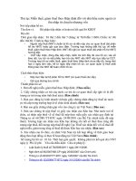
the other two. Ultrasonic frequencies can also be used to separate dust particles from the fabric. Fig. 9.1
(5) illustrates the use of ultrasonics and the cleaning of filters by mechanical shaking Fig. 9.1 (1–4).
One recent development which has improved the cleaning of filters is the introduction of a fabric
which is coated on one side with a ‘plastic’ membrane. The surface coated with plastic has a very small
pore structure compared with that of conventional material. This prevents the particles penetrating the
surface of the material and the particles much less tendency to adhere to the surface of the filter. It is
consequently easier to clean. It also allows the filter to operate for long periods with a lower pressure
drop (i.e. near to new fabric conditions) than is possible with traditional filter cloths.
Page 243
Fig. 9.1 Fabric bag cleaning with reverse air flow and ultrasonic vibration.
Fabrics have the advantage that they can be chosen to form the filter so that the required degree of
filtration is obtained. They are also resistant to attack by organic solvents should they be present in the
exhaust gases. Their main disadvantage is their physical size.
Page 244
9.4 WET SCRUBBERS
A simpler and cheaper piece of equipment than the cloth filter is the wet scrubber. This type of
equipment takes many forms but it essentially consists of a two-stage process taking place in one piece
of equipment. At first the exhaust air is mixed with water from a spray, to ensure that the solid particles
are wetted or captured by the drops of liquid. The air is then turned 180° and passed into a much larger
diameter chamber to reduce its velocity. In this stage the larger drops fall back and the smaller ones are
removed by the mist eliminator.
The design of the first part is critical and differs considerably from one manufacturer to another. The
objective here is to ensure maximum particle/water contact and the highest level of solids removal. If
good contact is achieved, a moderate proportion of submicron particles and over 90% of particles as
small as 5
µm can be eliminated.
The design of the second stage is equally important and again designs vary widely. The danger in this
part of the equipment is that any small droplets of water which do pass through the mist eliminator will
carry some solid particles, thus reducing the efficiency of the unit.
The main advantages are:
Its main disadvantage, if in fact it is a disadvantage, is the method of disposing of the solution/slurry
which collects in the base of the unit. It is usual to operate the unit on a closed system, i.e. the water is
not continuously run to waste. If the water was continuously run to waste the cost of the water used
could be quite considerable. After several batches of tablets have been coated, it is necessary to dispose
of the solution/slurry—which may contain a certain amount of active material—using a specifically
designed treatment system or a specialist waste disposal company. If scrubbers are used in conjunction
with a sugar-coating process, the dilute sugar solution which collects in the scrubber is an ideal medium
for bacterial growth. It is, therefore, essential that it is cleaned regularly. In fact scrubbers have been
referred to as units which turn an air pollution problem into a water pollution problem.
An added advantage compared to cyclones and fabric filters, the wet scrubber can also remove
organic solvents from the exhaust gases. This applies particularly to water-soluble solvents such as
alcohol.
9.5 CYCLONE SCRUBBERS
One of the ways of improving the efficiency of a water-
washing system for solids removal is to combine
the advantages of the cyclone with that of the simple scrubber. The design of this equipment also varies
widely. Water can be introduced at the top, bottom or even on the central axis. The wet cyclone offers
some advantages for
•
Its small size
—
considerably less that that required for the equivalent fabric filter.
•
Low maintenance costs.
•
Low power consumption.
Page 245
certain types of gas cleaning, but it is doubtful if this type of equipment could offer any substantial
advantages over a simple scrubber for the cleaning of exhaust gases from a tablet-coating plant.
9.6 ELECTROSTATIC PRECIPITATORS
Another type of gas cleaning used is electrostatic precipitation. It is very good for removing small
particles from gas streams. Electrostatic precipitators are capable of efficiencies as high as 97–98% for
particles down to 0.05 µm and are suitable for very large gas volumes. However, their installation and
running costs are much higher than for any of the other equipment described and there could be dangers
when inflammable solvents are used.
9.7 REMOVAL OF ORGANIC SOLVENTS
Some organic solvents can be removed by washing the exhaust air. However, the type of wet scrubber
already described is not designed to obtain the best results for the maximum removal of solvents. Other
problems occur if solvents such as methylene chloride are being used. Methylene chloride will, to some
extent, decompose to produce a dilute solution of hydrochloric acid, which is corrosive. To overcome
this problem one European pharmaceutical company has made the decision that all their organic
solvent-based coating will be carried out without the use of methylene chloride which has been replaced
by ethanol. This enables the exhaust gases from the coating plant to be removed by washing with water.
9.8 GAS ABSORPTION TOWERS
For the highest efficiency of solvent removal the equipment must ensure maximum exposure of gas and
liquid surfaces to each other. This can be done in three ways.
As with all types of gas cleaning equipment the design varies widely from one manufacturer to
another. Often more than one of these concepts are combined in different parts of the equipment.
One system which could be suitable for use with exhaust gases from a coating plant consists of two
towers, a short fairly large diameter tower and a much taller tower with a smaller diameter. In the first
tower water is sprayed as very fine droplets to remove some of the solvent. In the second tower the
gases flow upwards through a series of trays against a downward flow of water.
So much has been published on the design of these absorption towers and there are so many possible
designs for the internal structure that it is not possible to deal
1. The liquid can be broken up into a number of slow-moving films which are dispersed through
the gas.
2. The liquid can be broken up into as small a droplet size as possible and dispersed into the gas
steam.
3.
The gas can be broken up into small bubbles that are passed through the liquid.
Page 246
with all the variations. If this is considered an option then a specialist company should be consulted.
The main advantage of this type of cleaning process is that it is probably the cheapest means of
efficiently removing solvents such as alcohol. Its main disadvantage is that the solvent is lost as the
solution is normally too dilute for economic recovery.
9.9 CARBON ABSORPTION SYSTEMS
A carbon absorption plant consists of two or more towers each containing a bed of active carbon. Any
solid particles are first removed from the exhaust gases as these tend to block the carbon bed. The gases
are passed through the first tower or the first set of towers depending upon the total quantity of gases to
be treated. The solvent molecules are absorbed onto the carbon. This continues until a significant
amount of solvent can be detected in the gases leaving the tower, i.e. the carbon bed has become
saturated with solvent; here the gases are diverted to the second tower where absorption of the solvent
continues. The first tower is then stripped of solvent by passing steam through the carbon bed. The
steam/solvent vapours are condensed and the solvent/water mixture collected. The carbon bed is dried
and cooled ready for a second pass of the exhaust gases. The size of the plant is to some extent governed
by the time of the stripping, drying and cooling stages, in other words by the number of towers or the
size of tower that is required to absorb the solvent vapour until the first unit can be brought back into
use.
For tablet coating, which is frequently a batch process with a period between batches, it might be
possible to use just one tower. If the time between batches is sufficient for stripping, drying and cooling
to take place, or if the tower has a capacity to absorb the solvent from several batches before stripping,
then a one-tower system would be suitable which would reduce the capital cost of the plant.
The major disadvantage of this system is that the collector contains a mixture of solvents or solvents
and water. It is usually necessary to distil this mixture before the solvent can be reused and this requires
additional plant and higher capital investment. If a solvent mixture has been used which cannot be
completely separated by distillation, for example, an azeotropic mixture, then the problem is more
complex.
Various reports on the economics of operating this type of plant in connection with film coating give
different results. Early reports said that the value of the solvent recovered offset the operating costs of
the plant but the capital cost had to be considered as the cost of complying with antipollution legislation.
More recent reports indicate that it is possible to obtain a return on the capital invested but this depends
on the quality of the solvent recovered.
9.10 CONDENSATION SYSTEMS
The alternative method of recovering the solvents is by condensation. A very interesting paper was
published recently in
Die Pharmaceutical Industrie
by Koblitz,
Page 247
Bergbauer-Ehrhardt of Sandoz, Nürnberg, concerning this particular method. The experimental system
they are using has many advantages over carbon absorbers. The exhaust gases leaving the coating pan
are first filtered and then passed through an air to air heat exchanger, where they are cooled from about
45–50°C to about 7–8°C. The gases then pass into a condenser and cool in two or three stages to
−30°
C.
It can be shown from vapour pressure calculations that at this temperature 98% of the solvent vapour
will be condensed. The liquid is collected and here it is in a form that can be reused without further
treatment. The cold gases are then passed through the other side of the first exchanger, where they cool
the air leaving the coating plant before it enters the condenser and, in turn, are warmed by that air. The
exhaust gases then pass to a reheater. The reheater and condenser are linked by a heat pump so that at
least some of the heat removed is replaced. The gases are then returned to the coating pan via a final
heat exchanger which is used to raise their temperature to the required level.
This type of plant is expensive to install, but apart from preventing any pollution of the atmosphere, it
recovers the solvent in a usable form and reduces the heat input resulting in savings in operating costs.
One difficulty which can occur with this system is the control of any water which enters the system. If
ethyl alcohol in the form of Industrial Methylated Spirit is used it will contain water. This water, as well
as any entering the system from any other source, is likely to form ice on the heat exchanger surface of
the condenser, thus reducing the effectiveness of the condenser.
For companies that require a fully engineered recovery system, Glatt offer two systems—based on
closed loop and fluid bed vacuum—for solvents such as acetone, methylene chloride, ethyl alcohol
(ethanol), methyl alcohol (methanol) and isopropyl alcohol.
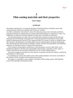
An example of a closed loop system for solvent recovery is shown in Fig. 9.2
, and an example of a
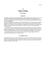
Glatt vacuum fluid bed dryer coater is shown in Fig. 9.3
.
There are various ways in which water can be removed, and these systems probably offer the most
cost effective ways of operating an organic solvent-based film-coating process.
Ten years ago it looked possible that aqueous-based film coating could take over completely and that
organic solvent-based coating could gradually die out, and this is generally true. However, quite a
number of companies have at least one product which must be coated from an organic solvent-based
coating and it will be necessary to ensure that all of the particulates and solvents from this product are
prevented from entering the environment. Once the equipment is installed for solvent recovery, and if it
is as economic to operate as condensation appears to be, then there is no reason why other products
should not be coated from organic solvent
-
based solutions.
Page 248
Fig. 9.2 Closed loop solvent recovery system (Glatt). 1. Fluid bed coating column, 2.
Condenser, 3. Solvent container, 4. Blower, 5. Gas heater.
Fig. 9.3 Fluid bed coating column with condensate solvent recovery. (Glatt) 1. Coating
column, 2. Fan and heater for fluid bed air, 3. Vacuum pump and condenser, 4.
Pump.